3/2 N: how to save on reliability increase?
Parallel uninterruptible power supply (UPS) configurations have been used in the industry for more than 35 years to protect critical loads. They are also used to ensure the fail-safe operation of critical data center applications. But which backup scheme to choose when building a commercial data center under conditions where, on the one hand, the budget is limited and, on the other, the protection of client equipment and applications is number one priority?
N + 1: LET IT IN COMMUNICATION WITH YOU ONE ...
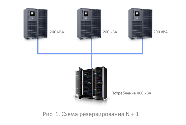
Currently, the most widespread are parallel systems with N + 1 redundancy (see Figure 1). If one source fails, the system will remain operational due to the fact that the backup UPS takes over the load. A parallel system can theoretically be collected from any number of sources - the main thing is that their total power should provide the nominal power that the load consumes, plus one backup source. In a parallel system designed more fractionally, the excess of the total power above the nominal will be less. For example, if the load is 400 kVA, then you can take three UPSs of 200 kVA (200 + 200 + 200). The excess power of such a system over the load power will be 200 kVA (50% relative to the load). But if you take less powerful UPSs, for example, 4 UPSs of 100 kVA each, then another identical system in reserve will provide a power takeover of only 100 kVA (25%).
')
It would seem that the fractional scheme is more economical ... But in practice, taking into account cables, commissioning, installation, installation, and even just the cost of the UPS, these benefits are not obvious, and the fractional system takes more space ... Therefore, with all that, at first glance, it is tempting prefer large fractionality, the scheme N + 1 usually reduced to 2 + 1, 3 + 1 - and extremely rarely to 4 + 1.
In data centers with critical load, the N + 1 scheme is used extremely rarely, and even then due to budget constraints. The weak point of this scheme is a single point of failure: the bus, through which the UPS is connected to the load. If necessary, routine maintenance (for example, when you need to tighten the bolts on the bus), the load will have to be disconnected from the UPS group. The most effective strategy in this case is to connect the load to the second feeder from the city.
2N - DOUBLE ARMOR
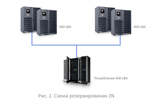
The ideology of the TIA 942 standard for data centers requires that the system continue to be operational, even if any of its elements have failed. Considering that almost all modern loads have two independent power supplies, a completely different wiring pattern, the “2N”, is quite natural. Each of the inputs (server power supplies) is powered by a separate UPS group (see Figure 2). Currently, there has been a desire of equipment manufacturers to increase the number of power supplies to three or more. So if in five years three or four power supply units will be widely practiced, the redundancy scheme can change accordingly from 2N to 3N or even 4N.
The comparison shows that the number of devices in the second scheme is larger, and accordingly it is more expensive. But from the point of view of reliability, the failure of any source or the whole group does not lead to a loss of load, which goes smoothly to the backup input.
3/2 N - STAR SOLUTION

The art of designing power protection systems allows you to maximize the reliability of the system, but at the same time significantly reduce capital costs. Such a solution is the scheme shown in Figure 3. Of course, this scheme is not an innovative discovery. In the world of DRUPS - diesel rotary UPS systems - this scheme is called IP-Star.
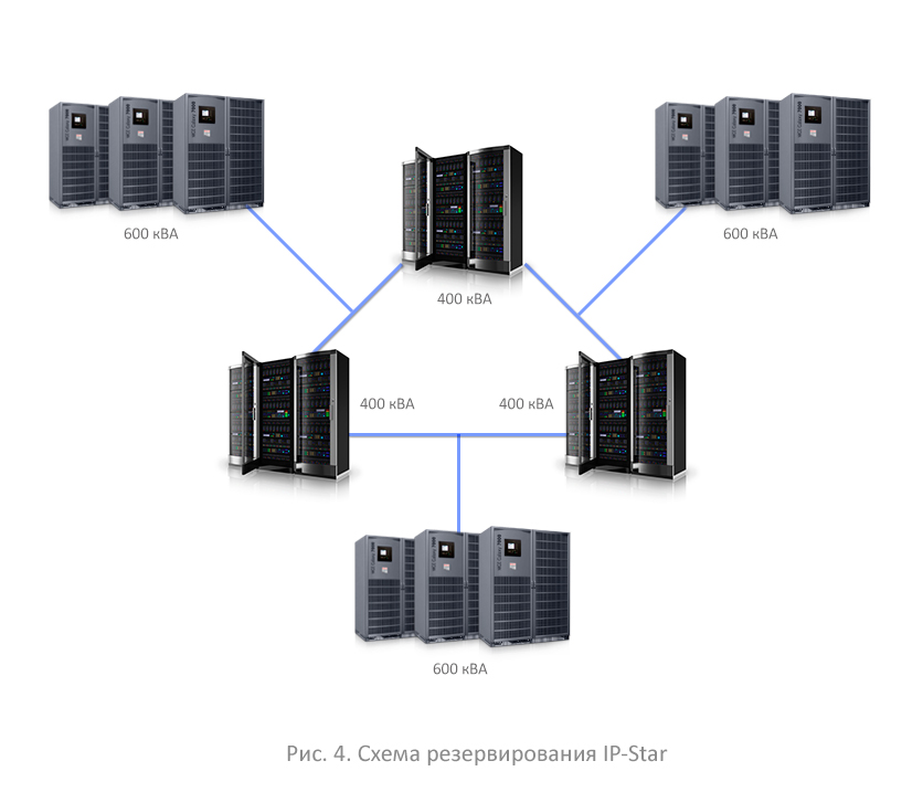
In Figure 4, this same scheme is represented as a star. Its use in the DataPro company in Tver allows you to maintain the level of reliability almost the same as in the 2N scheme, but at the same time significantly reduce capital costs.
In the new data center will be put into operation three server rooms. The total power consumption of the load of each room is 400 kVA. Each load in this circuit is connected to two active inputs. Each UPS group includes three 200 kVA sources each - two main and one backup. The total installed capacity in this case is 1800 kVA. It can be seen from the diagram that if one of the sources fails, the load is not lost with a high probability. And even if an accident occurs on the centralized bus of one of the UPS groups, the next group of UPS from another input will pick up the load. Obviously, if there were not three, but four rooms in the data center, the scheme would have been called not 3/2 N, but 4/3 N.
In normal operation, each of the loads is protected by uninterruptible power supplies from both inputs. When one of the rays disappears, the working capacity is preserved. The number of UPSs in this circuit is smaller compared to the 2N (3x200x4) = 2400 circuit, the system is cheaper - the advantages of the third circuit (3x200x3 = 1800 kVA) are obvious.
In general, in the third scheme, all the advantages of the 2N scheme are preserved. At the same time, the UPSs are loaded at 2/3 of the nominal value, not 50% as in the 2N scheme. Therefore, the efficiency is higher - respectively, the electricity bill is less. True, in high-quality sources, efficiency, depending on the degree of congestion, does not degrade much. But in general, both in capital expenditures and in operating expenses, Scheme 3 is cheaper than the 2N scheme, although it is somewhat more expensive than N + 1. And this is at almost the same level of reliability as the 2N.
DataPro's data center in Tver has a 3/2 N reservation scheme for the first time in Russia and is certified by the Uptime Institute.
Briefly about the main thing:
• DataPro Data Center in Tver
• The total area of the data center is 2650 sq.m.
• Maximum power 4.5 MW
• 4 machine rooms with the ability to accommodate up to 100 racks in each
• Designed capacity of IT equipment from 3 kW to 20 kW per rack
• Tier III Uptime Institute Design and Facility * Certification
• Commissioning in October 2013
Experts comment:
Sergey Ermakov - Technical Director of Inelt.
The problems that arise in the second connection scheme mainly lie in the plane of interaction with IT services. In fact, when operating such systems, the absence of one input for an IT team’s operational team means an alarm: the signal comes from the monitoring system and is recorded in the event log. It does not matter that the switch was envisaged by the circuit design and the process did not stop - for IT it is a reason to write reports that the power industry did not provide one of the inputs, and to start an internal investigation.
That is why, where a highly reliable solution is required, backup UPSs are provided for two levers, but then the 2N circuit threatens to transform into 2 (N + 1), which corresponds to Tier 4 and makes the solution even more expensive. There are intermediate solutions - N + (N + 1), when only one of the branches is reserved. The compromise is that in this case the number of alarms is reduced, but they are not eliminated at all.
To shorten the duration of alarms, you can enter a large number of cross-joints, which, in manual, automatic or semi-automatic mode, in the event of an accident, allow a backup UPS to be started. But traditionally, experts refer to mutual overlapping connections with caution, because when operating such systems, the probability of error due to carelessness is high. This can also be fought, but in general, all the tricks only complicate the scheme, which ultimately reduces the overall level of reliability.
Yury Kopylov - Technical Director of Eaton
Currently, there is an urgent task in data centers - reserving power to virtualized servers in a cloud computing environment. Depending on the manufacturer, this problem is already being solved by means of the UPS and the corresponding software and monitoring systems, which allow you not to wait until the power supply disappears completely, but to transfer critical applications to other virtual servers operating in another zone. Such solutions have already been proposed by Eaton: UPS and virtualization systems have already learned how to move the most critical applications to those virtual servers where there are no problems with the power of the physical IT infrastructure.
Interesting solutions can be obtained if modern “modular” UPSs are used in any of the considered schemes, where each of the UPSs is not a single 200 kVA device (as in the examples), and itself consists of intelligent modules operating in parallel mode. They not only provide internal redundancy and some redundancy of the UPS itself, increasing its reliability, but also, in conjunction with other UPSs of the parallel system, form a kind of “matrix structure” that automatically redistributes the total load among the working modules.
N + 1: LET IT IN COMMUNICATION WITH YOU ONE ...
Currently, the most widespread are parallel systems with N + 1 redundancy (see Figure 1). If one source fails, the system will remain operational due to the fact that the backup UPS takes over the load. A parallel system can theoretically be collected from any number of sources - the main thing is that their total power should provide the nominal power that the load consumes, plus one backup source. In a parallel system designed more fractionally, the excess of the total power above the nominal will be less. For example, if the load is 400 kVA, then you can take three UPSs of 200 kVA (200 + 200 + 200). The excess power of such a system over the load power will be 200 kVA (50% relative to the load). But if you take less powerful UPSs, for example, 4 UPSs of 100 kVA each, then another identical system in reserve will provide a power takeover of only 100 kVA (25%).
')
It would seem that the fractional scheme is more economical ... But in practice, taking into account cables, commissioning, installation, installation, and even just the cost of the UPS, these benefits are not obvious, and the fractional system takes more space ... Therefore, with all that, at first glance, it is tempting prefer large fractionality, the scheme N + 1 usually reduced to 2 + 1, 3 + 1 - and extremely rarely to 4 + 1.
In data centers with critical load, the N + 1 scheme is used extremely rarely, and even then due to budget constraints. The weak point of this scheme is a single point of failure: the bus, through which the UPS is connected to the load. If necessary, routine maintenance (for example, when you need to tighten the bolts on the bus), the load will have to be disconnected from the UPS group. The most effective strategy in this case is to connect the load to the second feeder from the city.
2N - DOUBLE ARMOR
The ideology of the TIA 942 standard for data centers requires that the system continue to be operational, even if any of its elements have failed. Considering that almost all modern loads have two independent power supplies, a completely different wiring pattern, the “2N”, is quite natural. Each of the inputs (server power supplies) is powered by a separate UPS group (see Figure 2). Currently, there has been a desire of equipment manufacturers to increase the number of power supplies to three or more. So if in five years three or four power supply units will be widely practiced, the redundancy scheme can change accordingly from 2N to 3N or even 4N.
The comparison shows that the number of devices in the second scheme is larger, and accordingly it is more expensive. But from the point of view of reliability, the failure of any source or the whole group does not lead to a loss of load, which goes smoothly to the backup input.
3/2 N - STAR SOLUTION
The art of designing power protection systems allows you to maximize the reliability of the system, but at the same time significantly reduce capital costs. Such a solution is the scheme shown in Figure 3. Of course, this scheme is not an innovative discovery. In the world of DRUPS - diesel rotary UPS systems - this scheme is called IP-Star.
In Figure 4, this same scheme is represented as a star. Its use in the DataPro company in Tver allows you to maintain the level of reliability almost the same as in the 2N scheme, but at the same time significantly reduce capital costs.
In the new data center will be put into operation three server rooms. The total power consumption of the load of each room is 400 kVA. Each load in this circuit is connected to two active inputs. Each UPS group includes three 200 kVA sources each - two main and one backup. The total installed capacity in this case is 1800 kVA. It can be seen from the diagram that if one of the sources fails, the load is not lost with a high probability. And even if an accident occurs on the centralized bus of one of the UPS groups, the next group of UPS from another input will pick up the load. Obviously, if there were not three, but four rooms in the data center, the scheme would have been called not 3/2 N, but 4/3 N.
In normal operation, each of the loads is protected by uninterruptible power supplies from both inputs. When one of the rays disappears, the working capacity is preserved. The number of UPSs in this circuit is smaller compared to the 2N (3x200x4) = 2400 circuit, the system is cheaper - the advantages of the third circuit (3x200x3 = 1800 kVA) are obvious.
In general, in the third scheme, all the advantages of the 2N scheme are preserved. At the same time, the UPSs are loaded at 2/3 of the nominal value, not 50% as in the 2N scheme. Therefore, the efficiency is higher - respectively, the electricity bill is less. True, in high-quality sources, efficiency, depending on the degree of congestion, does not degrade much. But in general, both in capital expenditures and in operating expenses, Scheme 3 is cheaper than the 2N scheme, although it is somewhat more expensive than N + 1. And this is at almost the same level of reliability as the 2N.
DataPro's data center in Tver has a 3/2 N reservation scheme for the first time in Russia and is certified by the Uptime Institute.
Briefly about the main thing:
• DataPro Data Center in Tver
• The total area of the data center is 2650 sq.m.
• Maximum power 4.5 MW
• 4 machine rooms with the ability to accommodate up to 100 racks in each
• Designed capacity of IT equipment from 3 kW to 20 kW per rack
• Tier III Uptime Institute Design and Facility * Certification
• Commissioning in October 2013
Experts comment:
Sergey Ermakov - Technical Director of Inelt.
The problems that arise in the second connection scheme mainly lie in the plane of interaction with IT services. In fact, when operating such systems, the absence of one input for an IT team’s operational team means an alarm: the signal comes from the monitoring system and is recorded in the event log. It does not matter that the switch was envisaged by the circuit design and the process did not stop - for IT it is a reason to write reports that the power industry did not provide one of the inputs, and to start an internal investigation.
That is why, where a highly reliable solution is required, backup UPSs are provided for two levers, but then the 2N circuit threatens to transform into 2 (N + 1), which corresponds to Tier 4 and makes the solution even more expensive. There are intermediate solutions - N + (N + 1), when only one of the branches is reserved. The compromise is that in this case the number of alarms is reduced, but they are not eliminated at all.
To shorten the duration of alarms, you can enter a large number of cross-joints, which, in manual, automatic or semi-automatic mode, in the event of an accident, allow a backup UPS to be started. But traditionally, experts refer to mutual overlapping connections with caution, because when operating such systems, the probability of error due to carelessness is high. This can also be fought, but in general, all the tricks only complicate the scheme, which ultimately reduces the overall level of reliability.
Yury Kopylov - Technical Director of Eaton
Currently, there is an urgent task in data centers - reserving power to virtualized servers in a cloud computing environment. Depending on the manufacturer, this problem is already being solved by means of the UPS and the corresponding software and monitoring systems, which allow you not to wait until the power supply disappears completely, but to transfer critical applications to other virtual servers operating in another zone. Such solutions have already been proposed by Eaton: UPS and virtualization systems have already learned how to move the most critical applications to those virtual servers where there are no problems with the power of the physical IT infrastructure.
Interesting solutions can be obtained if modern “modular” UPSs are used in any of the considered schemes, where each of the UPSs is not a single 200 kVA device (as in the examples), and itself consists of intelligent modules operating in parallel mode. They not only provide internal redundancy and some redundancy of the UPS itself, increasing its reliability, but also, in conjunction with other UPSs of the parallel system, form a kind of “matrix structure” that automatically redistributes the total load among the working modules.
Source: https://habr.com/ru/post/199426/
All Articles