Universal Autotest, or how we automated the API manual tests in nanoCAD
How can I manually test the API? On the contrary, if there is an API, what are the bad unit tests? When developing the nanoCAD API, we were faced with the fact that not all of the API can be tested using unit tests - part of the API is inextricably linked with the user interface and interactive user interaction.
In this article, we will talk about how we tested the API manually, what stages of automation we went through, and what approach allowed us to create robust and easily supported autotests.
')
Based on the report at the SQA Days-12 conference.
Tasks for testing nanoCAD can be divided into two main groups. The first is testing nanoCAD as a constructor tool, where the main question is: “Can the designer draw what is required?”. The second group - API tests, here we are looking for the answer to another question: "Can those applications work that should work?".
With manual tests of the program in which the user works, everything is clear. And what is the manual API test? And why not use standard unit tests for API testing?
Indeed, unit tests are suitable for testing a significant part of the API. But there are a number of functions, the call of which leads to a user action request. For example, an application, by calling the function GetPoint () or GetAngle (), may ask the user to enter a point or angle. In order to test how this functionality works, we need to create a test application that calls API functions with all the main parameter options, but to automate such tests we will need to automate user actions in some way.
The scheme of manual tests API has the following form:
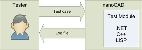
To test each API function, a separate command was written. The tester runs the commands manually, then he selects points on the screen, enters the coordinates, etc. according to the test case.
Upon completion, the test case is analyzed log file.
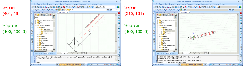
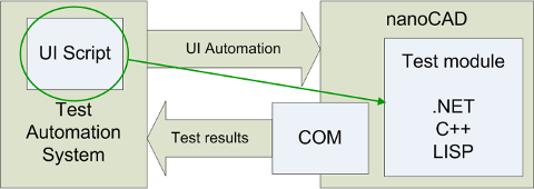
Starting automation, we started by pressing the “red button” and recorded the script. A miracle did not happen, all points, as expected, were recorded in screen coordinates.
What to do? The screen coordinate system is not suitable, since the position of the drawing elements on the screen may vary, and a reliable auto test should not depend on:
The answer suggested itself: you need to store the points in the coordinate system of the drawing.
But how during the test to convert the coordinates of the drawing in screen coordinates?
The traditional way to solve this problem is to create an adapter for an automated testing system, which is loaded into nanoCAD and recalculates coordinates. However, the creation of such an adapter binds to a specific automated testing system, we decided to avoid this whenever possible, and instead use the existing software interface.
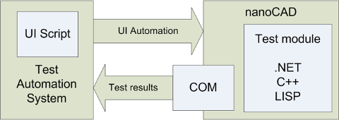
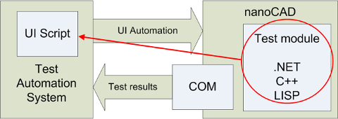
We have added the COM model with conversions from the screen to the drawing and back:
and replaced the tester in the test scheme on the automated testing system:
Now our automated test looks like this:
One of the drawbacks of this approach is the inability to automatically write such a script — when writing, the screen coordinates should be dynamically converted to the coordinates of the drawing. In the presence of a full-fledged adapter, this problem could be solved.
The main disadvantage of this approach is that the test logic is divided into two parts. The test itself is loaded into nanoCAD, and the automation script is loaded into the automated testing system. Such tests are hard to maintain and debug: any change in the test logic requires the simultaneous introduction of changes to two different modules.
We decided to eliminate this drawback and to ensure that all the logic of the test was in one module. Two options were considered:
The first option is not suitable, as it deprives us of the possibility of a manual test run. We chose the second option, the library that each universal autotest uses, we called the “universal player”.
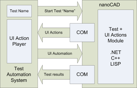
Despite the fact that the test scheme seems more complicated than the previous ones, it became much easier to maintain tests. Now, the AutoTest script contains only the test name and the launch code of the universal player. The universal player requests a list of actions from the test module and executes them sequentially.
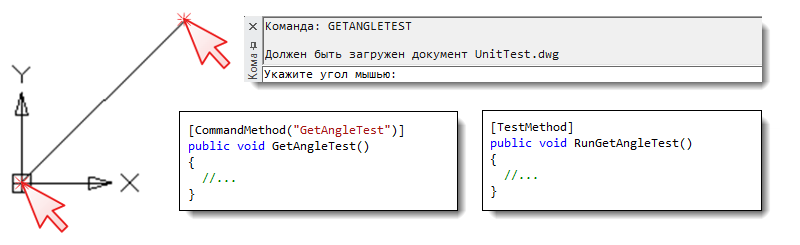
How does all this look in practice? Let's return to the example - the test of the GetAngle () function, which was mentioned at the beginning of the article.
The GetAngleTest command loaded into nanoCAD can be launched both manually and automatically.
The automated RunGetAngleTest test only performs the actions that were sent to it from the GetAngleTest command.
Currently, Universal Player is written only for Visual Studio Coded UI Tests. But, theoretically, to transfer autotests to another system, it is enough to rewrite the universal player - we used only the basic functionality that is in each automated testing system.
By the way, did you notice that our company has vacancies for testers ?
Discussion of the article is also available on our forum: forum.nanocad.ru/index.php?showtopic=6513 .
In this article, we will talk about how we tested the API manually, what stages of automation we went through, and what approach allowed us to create robust and easily supported autotests.
')
Based on the report at the SQA Days-12 conference.
Tasks for testing nanoCAD can be divided into two main groups. The first is testing nanoCAD as a constructor tool, where the main question is: “Can the designer draw what is required?”. The second group - API tests, here we are looking for the answer to another question: "Can those applications work that should work?".
With manual tests of the program in which the user works, everything is clear. And what is the manual API test? And why not use standard unit tests for API testing?
Indeed, unit tests are suitable for testing a significant part of the API. But there are a number of functions, the call of which leads to a user action request. For example, an application, by calling the function GetPoint () or GetAngle (), may ask the user to enter a point or angle. In order to test how this functionality works, we need to create a test application that calls API functions with all the main parameter options, but to automate such tests we will need to automate user actions in some way.
The scheme of manual tests API has the following form:
To test each API function, a separate command was written. The tester runs the commands manually, then he selects points on the screen, enters the coordinates, etc. according to the test case.
: GetAngleTest UnitTest.dwg , : 0,0,0 : 100,100,0 . Esc: <Esc> 0. 0: 0 0. 0: 0 . 0. 0: 1 . Enter : <Enter> . Enter : <Space> . Enter : 1 . Enter : <Enter> . : #sqadays12 . Enter <135>: <Space> . [/-/]: . Enter <135> [/-/]: <Enter> Upon completion, the test case is analyzed log file.
Starting automation, we started by pressing the “red button” and recorded the script. A miracle did not happen, all points, as expected, were recorded in screen coordinates.
Window.MouseClick(100, 200); // What to do? The screen coordinate system is not suitable, since the position of the drawing elements on the screen may vary, and a reliable auto test should not depend on:
- the size and interposition of the application window and its control panels,
- displaying controls in different OS versions, from OS styles,
- multi-monitor configurations
- and much, much more ...
The answer suggested itself: you need to store the points in the coordinate system of the drawing.
But how during the test to convert the coordinates of the drawing in screen coordinates?
The traditional way to solve this problem is to create an adapter for an automated testing system, which is loaded into nanoCAD and recalculates coordinates. However, the creation of such an adapter binds to a specific automated testing system, we decided to avoid this whenever possible, and instead use the existing software interface.
We have added the COM model with conversions from the screen to the drawing and back:
nanoCAD.Utility.CoordFromPixelToWorld() nanoCAD.Utility.CoordFromWorldToPixel() and replaced the tester in the test scheme on the automated testing system:
Now our automated test looks like this:
x_drawing = 3.14; // : y_drawing = 159265; // FromWorldToPixel(x_drawing, y_drawing, x_screen, y_screen); Window.MouseClick(x_screen, y_screen); // 100, 200, // . One of the drawbacks of this approach is the inability to automatically write such a script — when writing, the screen coordinates should be dynamically converted to the coordinates of the drawing. In the presence of a full-fledged adapter, this problem could be solved.
The main disadvantage of this approach is that the test logic is divided into two parts. The test itself is loaded into nanoCAD, and the automation script is loaded into the automated testing system. Such tests are hard to maintain and debug: any change in the test logic requires the simultaneous introduction of changes to two different modules.
We decided to eliminate this drawback and to ensure that all the logic of the test was in one module. Two options were considered:
- The test logic is located in the automated testing system, a universal test is loaded into nanoCAD, which performs the actions transferred from the auto test lead
- The test logic is located in nanoCAD. A universal autotest is loaded into the automated testing system; it performs the actions transferred from the host test
The first option is not suitable, as it deprives us of the possibility of a manual test run. We chose the second option, the library that each universal autotest uses, we called the “universal player”.
Despite the fact that the test scheme seems more complicated than the previous ones, it became much easier to maintain tests. Now, the AutoTest script contains only the test name and the launch code of the universal player. The universal player requests a list of actions from the test module and executes them sequentially.
How does all this look in practice? Let's return to the example - the test of the GetAngle () function, which was mentioned at the beginning of the article.
: GetAngleTest ... , : 0,0,0 : 100,100,0 ... The GetAngleTest command loaded into nanoCAD can be launched both manually and automatically.
[CommandMethod("GetAngleTest")] public void GetAngleTest() { // UI testRunner.AddAction(new ActionClickDocument(0, 0, 0)); testRunner.AddAction(new ActionClickDocument(100, 100, 0)); testRunner.SendActions(); // EditorInput.Editor.GetAngle() PromptAngleOptions opts = new PromptAngleOptions(" "); PromptDoubleResult pr = this.ed.GetAngle(opts); // thisAssert.IsTrue((pr.Status == PromptStatus.OK) && (pr.Value > 0), " . " + pr.ToString()); } The automated RunGetAngleTest test only performs the actions that were sent to it from the GetAngleTest command.
[TestMethod] public void RunGetAngleTest() { // 'GETANGLETEST' Keyboard.SendKeys(uICommandLineEdit, "GETANGLETEST{Enter}", ModifierKeys.None); // UI this.ProcessUIActions(context); } Currently, Universal Player is written only for Visual Studio Coded UI Tests. But, theoretically, to transfer autotests to another system, it is enough to rewrite the universal player - we used only the basic functionality that is in each automated testing system.
By the way, did you notice that our company has vacancies for testers ?
Discussion of the article is also available on our forum: forum.nanocad.ru/index.php?showtopic=6513 .
Source: https://habr.com/ru/post/199402/
All Articles