Network for the smallest. Micro issue №4. Immersion in IOU
 Continuing, or rather completing the overview of various emulators of Cisco Systems equipment, I will focus on Cisco IOU (Cisco IOS on UNIX).
It is this emulator that contains the maximum number of features and the minimum number of restrictions on functionality (I remind you that it does not apply and only Cisco employees are allowed).
Its main advantages are that it is fast enough and works well with the channel level.
To be as precise as possible, IOU works only under Solaris, and IOL is launched under Linux, but everyone is accustomed to using one common name, therefore, in the article I will stick to the general name.
Consider it from beginning to end, from installation to configuration, and at the end of the curtain we will release it into the real network.
Those who are only interested in setting up an IOU can skip the installation step and go straight to setting up an IOU .
Installation
So, at the beginning of the installation.
We will not consider options with the pre-installed IOU, there are a lot of different assemblies, but it is much more interesting to assemble everything by hand.
So let's go from scratch.
In order to independently assemble IOUs, a basic knowledge of Unix-like systems is required.
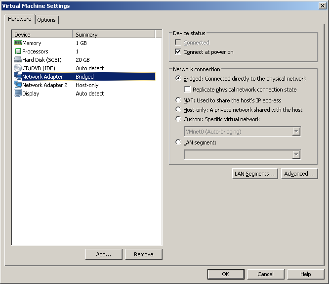
Take Linux, for example, rpm-based CentOS (although the option is also possible using Debian). And virtualization tool - VMware or VirtualBox to taste. Although using VirtualBox, the Cloud will not work (that is, it will not be possible to release IOUs to the real network).
First you need to create a virtual machine and install CentOS (this process is beyond the scope of the article and is not particularly difficult, but you can read about the installation, for example, here or here .
After that, make sure that the virtual machine has two virtual network interfaces.
One of the interfaces will go to the real network ( bridge mode), and the second - to control IOU ( host-only ).
')
And configure them accordingly:
# vi /etc/sysconfig/network-scripts/ifcfg-eth0 and
# vi /etc/sysconfig/network-scripts/ifcfg-eth1 Key strings will consist of
DEVICE="eth0" BOOTPROTO=static ONBOOT=yes IPADDR=xxx.xxx.xxx.xxx NETMASK=255.255.255.0 in the case of a static address and
DEVICE=eth0 BOOTPROTO=dhcp ONBOOT=yes DHCP. As you can see, you need to specify a static IP address, a mask or DHCP, and restart the network subsystem for the changes to take effect:
# service network restart For correct operation of the IOU and especially for simplicity, you can disable SELinux and iptables.
You can view the current SELinux mode by running:
# sestatus To disable it before the first reboot, just run:
# echo 0 >/selinux/enforce For permanent changes, you can edit its configuration file to this:
# cat /etc/sysconfig/selinux # This file controls the state of SELinux on the system. # SELINUX= can take one of these three values: # enforcing - SELinux security policy is enforced. # permissive - SELinux prints warnings instead of enforcing. # disabled - No SELinux policy is loaded. SELINUX=permissive # SELINUXTYPE= can take one of these two values: # targeted - Targeted processes are protected, # mls - Multi Level Security protection. SELINUXTYPE=targeted And disabling the firewall:
# service iptables stop # chkconfig iptables off After that go to the installation of the web frontend.
Most recently, it has been updated to version 1.2.2-21
From the new:
- New OVF format: it is smaller and easier to install;
- It got faster: the code was rewritten, the database was optimized;
- Instead of ioulive86 now iou2net.pl: The cloud can be started before the start of IOU;
- Now more than one Cloud is supported;
- iousniffer: it became possible to analyze traffic;
- Selective import: you can choose what you want to import;
- Added html image maps: images can now become active links;
- Added countdown: useful for those who work out the tasks for the CCIE;
- Delayed loading: device loading may be delayed;
- Web console: earned a web console, but access requires unprivileged ports (32768-61000);
- Reset console: you can reset on all or one terminal connection;
- It is recommended to use the Google Chrome browser;
- Many bugs fixed;
First you need to create the file /etc/yum.repos.d/iou-web.repo with the following contents:
# /etc/yum.repos.d/iou-web.repo [iou-web] name=IOU Web Interface baseurl=http://public.routereflector.com/iou-web/yum enabled=1 gpgcheck=1 gpgkey=http://public.routereflector.com/iou-web/yum/RPM-GPG-KEY-iou-web This will add a new repository to the system, from which iou-web will be installed and updated.
Then you actually need to install iou-web:
# yum install iou-web And create a symlink on libcrypto.so.4 without which neither l2 nor l3 starts:
# ln -s /usr/lib/libcrypto.so.10 /usr/lib/libcrypto.so.4 All necessary missing dependencies (like apache and php) will be pulled up during the installation of iou-web.
The files will appear in the / opt / iou directory , moreover, the necessary configs for the web server will appear.
There will also be an entry at the end of the / etc / hosts file:
# tail -n 1 /etc/hosts 127.0.0.127 xml.cisco.com This string is likely to block the ability to send information to the Cisco server.
The apache config (in which xml.cisco.com is also found) will appear:
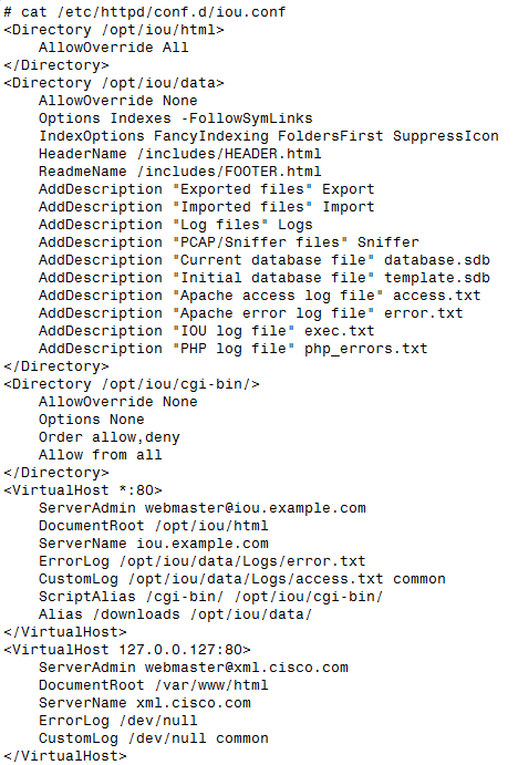
There is no need to make changes, everything will work right away.
It can be seen that Andrea Dainese (developer of iou-web) tried to simplify the lives of users as much as possible and to reduce the number of additional actions to a minimum.
It remains to start the web server
# service httpd start and specify the launch at each system boot:
# chkconfig httpd on This completes the web-frontend installation.
Customization
To log into iou-web, you just need to know the IP-address of the interface, which works in host-only mode.
# ifconfig eth1 eth1 Link encap:Ethernet HWaddr 00:0C:29:19:D8:CD inet addr:192.168.xxx.xxx Bcast:192.168.xxx.255 Mask:255.255.255.0 UP BROADCAST RUNNING MULTICAST MTU:1500 Metric:1 RX packets:10 errors:0 dropped:0 overruns:0 frame:0 TX packets:13 errors:0 dropped:0 overruns:0 carrier:0 After that, just open the browser (Google Chrome is recommended) and indicate this IP address there.
Before the eyes will appear a web front-end, quite minimalistic, but with a nice design.
There is no installation directly of the IOU as such; you just need to copy the files (using Upload IOS) that were compiled under Linux.
It will take two parts - l2 and l3.
Cisco keeps up with the times, and these two levels are not clearly divided into channel and network. Currently, L3 is more or less compliant with the ISR level router, and L2 is a multi-switch with a 3560 level switch.
The latest version for today is IOS 15.2 for routers and IOS 15.1 for switches.
After l2 and l3 have been received, you can open the web interface and download these files.
To do this, go to Manage - Manage IOS , specify the full file name, alias (alias) which will then be displayed during the creation of the topology, for example L3 15.2, pressing open, select the file and finally the upload button will load IOU into the virtual machine in the / opt / directory iou / bin .

You can proceed to use.
But if you try to run any topology, you get the error message “you must fill license file (/ opt / iou / bin / iourc) before starting devices” .
As the author of the web interface writes, contact your boss in the Cisco department for a license.
IOU looks in the iourc file each time it runs for a license key.
In a nutshell about licensing.
A license consists of a key that uses information about the current host; when you try to move or copy to another host, the use of an IOU becomes impossible.
But in reality, everything is somewhat different.
Note: The author of the article ( sinist3r ) is not the author of the license generator, and does not urge to use it in any way. Information is provided solely for information.
The license generation script was written by user Kel in 2011. He ported to Python the original code written in C in 2006.
The script itself, for obvious reasons, is not given.
To use it, you need to add a bit for execution:
#chmod 0755 CiscoIOUKeygen.py And actually launch:
./CiscoIOUKeygen.py View output
[license]
hostname = key;
You will need to copy and paste in the section Manage - Manage license .
And completing the setting, the final touch.
By default, clicking on devices will launch a standard telnet client.
This is not very convenient, especially considering that it is not preinstalled in recent versions of Windows. Much more familiar to use PuTTY.
In order for PuTTY to open on a browser click, you need to create a file for the registry like this:
Windows Registry Editor Version 5.00 [HKEY_CLASSES_ROOT\telnet] @="URL:Telnet Protocol" "EditFlags"=dword:00000002 "URL Protocol"="" "FriendlyTypeName"="@C:\\WINDOWS\\system32\\ieframe.dll.mui,-907" [HKEY_CLASSES_ROOT\telnet\DefaultIcon] @=hex(2):25,00,53,00,79,00,73,00,74,00,65,00,6d,00,52,00,6f,00,6f,00,74,00,25,\ 00,5c,00,73,00,79,00,73,00,74,00,65,00,6d,00,33,00,32,00,5c,00,75,00,72,00,\ 6c,00,2e,00,64,00,6c,00,6c,00,2c,00,30,00,00,00 [HKEY_CLASSES_ROOT\telnet\shell] [HKEY_CLASSES_ROOT\telnet\shell\open] [HKEY_CLASSES_ROOT\telnet\shell\open\command] @="\"C:\\Program Files\\PuTTY\\putty.exe\" %1" Naturally, do not forget to indicate the correct location of PuTTY.
In the case of a 64-bit system, the last line will look like:
@="\"C:\\Program Files (x86)\\PuTTY\\putty.exe\" %1" After that, save the file in with the reg extension, run and accept the changes.
And now we come to the most interesting - we create our own topology.
Create your topology in IOU
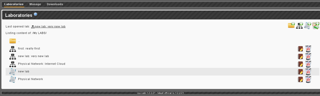
In order to create a new stand / laboratory, you need to go to the Laboratories section and click on Add new Lab .
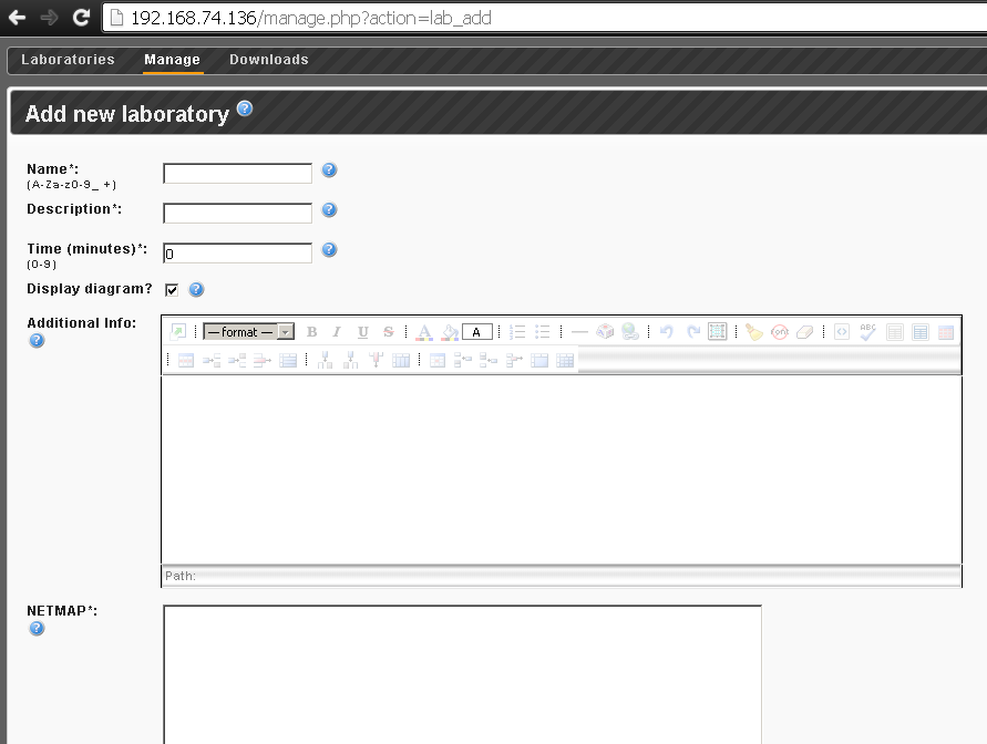
A page will open on which you will need to fill in the following fields:
Name, Description - the name and description play a purely informational role.
Time - a reverse report that can be set, probably makes sense when preparing for the CCIE.
Display diagram? - if enabled, the topology with all devices (which can be dragged by the cursor) will be shown; if turned off, only “active images” will remain - these are fixed schemes with clickable devices (with drawn areas, port numbers, etc.)
Additional Info - here you can write questions, or some other text.
Netmap - this is where the connections between devices are set.
Here it is worth making a small digression and consider several features of IOU.
IOU L3 supports two NM-4E and NM-4T network modules for Ethernet and Serial, respectively.
When choosing both modules, Ethernet always goes first.
IOU L2 - only supports Ethernet.
For example, one NM-4E and one NM-4T looks like: e0 / 0-0 / 3, s1 / 0-1 / 3
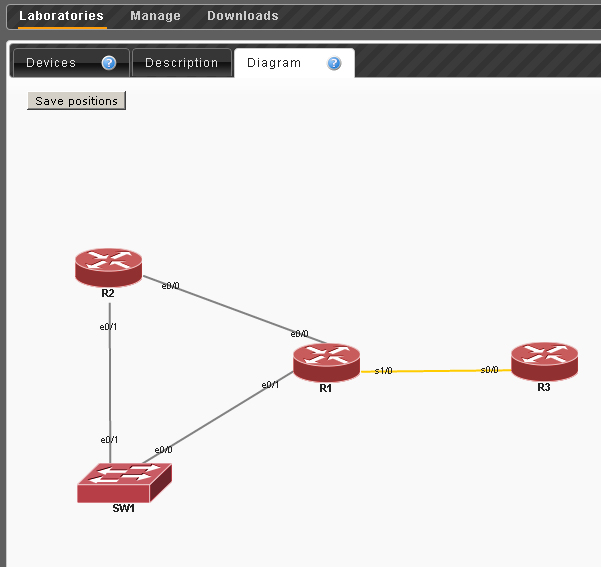
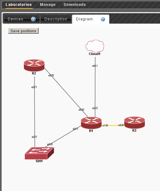
Suppose we want to create the following stand:
R1 e0 / 0 which is connected to R2 e0 / 0
R1 s1 / 0 is connected to R3 s0 / 0
R1 e0 / 1 - SW1 e0 / 0
R2 e0 / 1 - SW1 e0 / 1
Then the netmap syntax is as follows:
1:0/0 2:0/0 1:1/0 3:0/0 1:0/1 4:0/0 2:0/1 4:0/1 The first digit is the device ID (an arbitrary value that plays a rather informational role, a good idea for it to match the device number in the name) and then the slot number / port number is indicated after the colon. As you can see, this is practically the standard naming of Cisco interfaces.
After that, click Add . As a result, many more settings will appear.

Consider the Apply an Initial Config Pack to all device later.
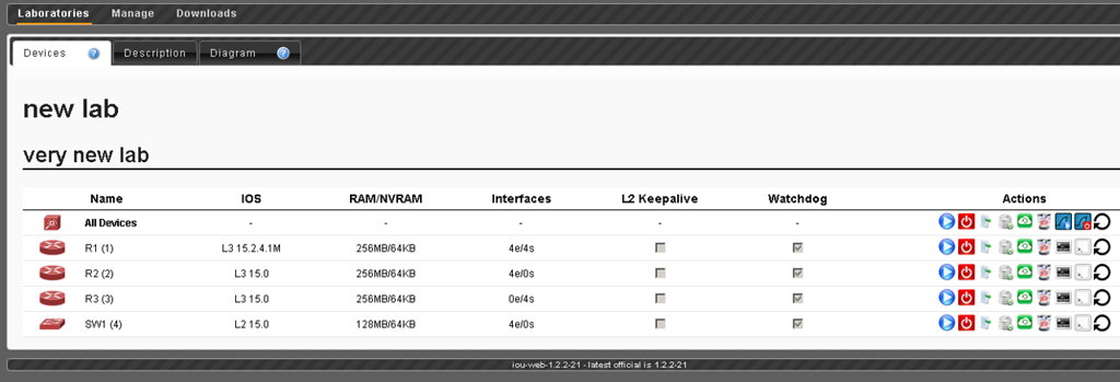
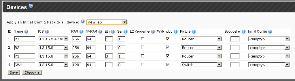
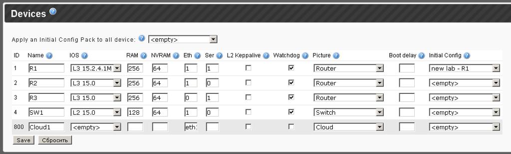
At this stage, just enter the names and select the appropriate IOS.
Next you need to fill in the RAM and NVRAM fields, for the 15th IOS at least 256RAM and 64 NVRAM are recommended.
And now the most important thing is the interfaces.
It is important not to leave the Eth and Ser fields empty - otherwise 8 NM modules will be added.
It turns out that for R1 we have 1 NM-4E and 1 NM-4T, for R2 - 1 NM-4E and 0 NM-4T, for R3 - only Serial, then 0 NM-4E and 1 NM-4T and for SW1 - 1 NM-4E and 0 NM-4T.
Next we see the keepalive check L2 - this technology corrects the situation when the interface is up, even if everything is off at the other end. It works only in pure switch labs, it is recommended not to include it in mixed topologies.
Watchdog - the author of iou-web highly recommends leaving it always on.
Cisco processors have timers that protect the system from certain types of hangs. The CPU periodically resets the watchdog timer. The watchdog timer basically controls the time of each process. If the duration of the process is longer than it should be, the watchdog timer is used to complete the process.
Then comes a drop-down list allowing you to select the type of device and the corresponding image.
The option - Boot delay - allows you to set a delay in seconds before launch, for example, you can set all devices to start immediately, and some routers after 20 seconds.
And the last option Initial Config - directly depends on the Initial Config Pack - and so far will be left unchanged.
In addition, the Images section is still below, which allows you to upload your images in png format.
For example, you can draw diagrams in Dia / Visio and then load them into stands.
Click save and go to the newly created stand by clicking on it.
On the Diagram tab - you can place devices to taste and save the location.
And on the Devices tab, the main control takes place.
By pressing the Start all devices button, you can actually start the stand.
Now, after clicking on the open console button, a terminal window will open next to each device (putty, if changes have been added to the registry).
Clicking on the icon with the image of Wireshark, you can start sniffing traffic.
You can collect saved pcap files in the Downloads - Sniffer section.
Returning to the missing option Initial Config Pack .
If desired, you can configure all devices, save the settings with the wr command, and then on each device, type copy running-config unix: in order to save configs to disk.
Then click the Copy all unix: // running-config files to database button in order to export all configs.
And now you can go to the Laboratories section and see the newly created config pack.
This file will be named the same as the stand itself, but only without a description.
Now you can enter the stand editing mode and select the newly created config in the Apply an Initial Config Pack to all device menu and save the changes.
In order for them to take effect, in the Devices tab click the button "stop all devices and wipe all configurations" . And now you can run a stand with config pack.
IOU in real network
Now let's try to bring all this to the real network.
To do this, IOU uses the concept of clouds (up to 8 pieces).
Head into the lab's edit mode.
Take the R1 router, an Ethernet module.
For the Cloud, clearly use large ID values, for example, 800
Let's add one line in the NETMAP field:
1:0/2 800:0/0 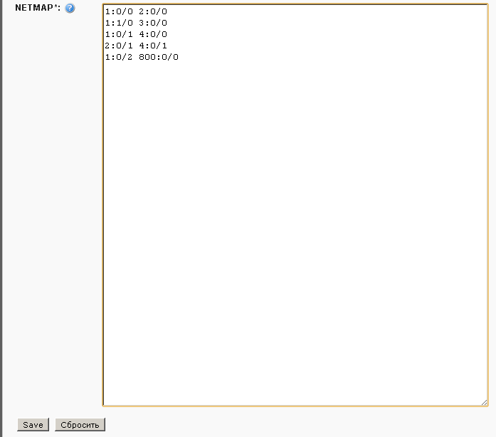
Save and go to the already familiar advanced editing mode.
The name is arbitrary, the IOS field must be left empty.
In the ethernet field, type eth1, in case eth1 is a virtual network adapter that, in bridge mode, looks into the existing network.
Then select Picture - Cloud (this is quite important).
And, in fact, save the result and run all the devices.
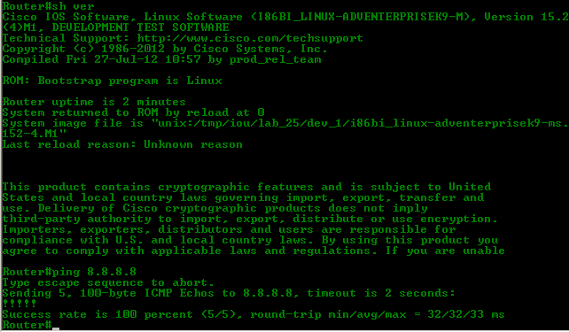
We see that the goal has been achieved.
Results
With the advent of the linux version and the web-frontend, working with IOU is not particularly difficult, everything is implemented quite logically.
In many cases, this emulator leaves GNS / Dynamips far behind, especially when it comes to the data link layer and switches.
IOU is still the best tool for preparing for CCNP / CCIE, as well as for troubleshooting.
During the writing process, materials from the Route Reflector website were mainly used.
A netvolart user got ahead of me by releasing an article with partially overlapping material.
As always, all articles of the cycle can be found on the site linkmeup.ru.
All releases of the first linkmeup podcast are also located there.
Source: https://habr.com/ru/post/199138/
All Articles