Smart home, as I sunk to such. Part 3
In the first part, we figured out why everything was needed and how I had come to this, and in the second part we talked about software. It is time to dwell on the most favorite habravchanami section DIY - on the gland. So, we take textolite, ferric chloride, a soldering iron ... But no, stop, open the board editor. About a soldering iron, where to put it, and where better it is not necessary, others will tell me better. And I will tell you what boards and sensors work for the benefit of my smart home.
Tire
I use a four-wire telephone cable as a bus.
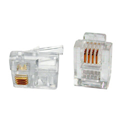
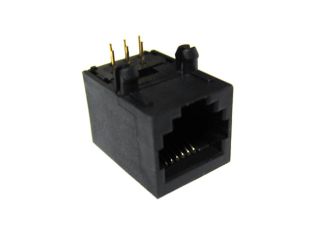
All cables are crimped plugs TP6P4C (RJ11).
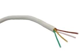
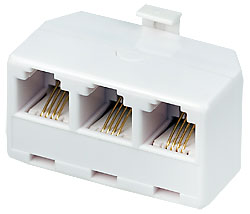
Connections and branches occur via standard telephone connectors and splitters.
Pinout made in accordance with the first purchased cards
')
- (green) - 12V
- (white) - 1-wire data
- (brown) - ground
- (yellow) - not used
In the first boards I purchased, the 4th contact was not used and, accordingly, did not switch in the end devices, therefore, it remained unused. In some schemes, 18V is supplied to the fourth contact. But, if I did everything from scratch, then I let 5V in there to power the thermal sensors.
Thermal Sensors DS18B20
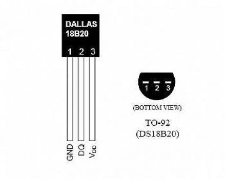
Not knowing about the features of working on parasitic power (blocking the bus from 0.3 to 1.5 seconds when prompted), I just connected pin 1 to ground, and pin 2 to 1-wire.
Now I add new sensors in places where there are other boards from which you can take 5V. In the future, I want to equip old sensors with power conversion circuits and power them correctly.
Thus, the “correct” connection scheme looks like this:
- Leg 1 - ground
- Leg 2 - to 1-wire bus
- Leg 3 - 5V
DS2413 boards
As I said earlier, I bought the first boards. I bought them here www.ab-log.ru/smart-house/1-wire-modules/2ch-module
The only disadvantage of this board, at that time, was the lack of transit of the fourth line, but now it has been fixed and it is present. As a pleasant feature, you can note the presence of LEDs, which is very convenient for debugging. On my boards I was too lazy to do wiring for LEDs, so I had to be debugged with a tester.
Schemes of the first homemade boards were peeped here www.benuks.ru/oborud.html#9
Scheme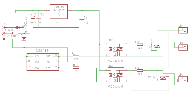
Pay
Actually, according to the functionality, they are completely identical to the purchased ones and are a dual-channel switch for controlling the load 220V.
DS2408 boards
There was already where to turn fantasy.
The idea of the first board on the DS2408 arose when I did the lighting in the kitchen. I wanted to make four independent zones of lighting and circuit boards on the DS2413, it would take two pieces. As a result, the scheme was born on the DS2408 which, in fact, differed only in the replicated MOC3043M + BT138 groups. He brought all eight, three, so to speak, for future development. (Unfortunately, the scheme was not preserved.)
The following two boards on the DS2408 were read only data. The first one receives data from the opening sensors of all windows and the door to the loggia, the second one receives data from door locks and motion sensors in the common corridor and near the door.
Scheme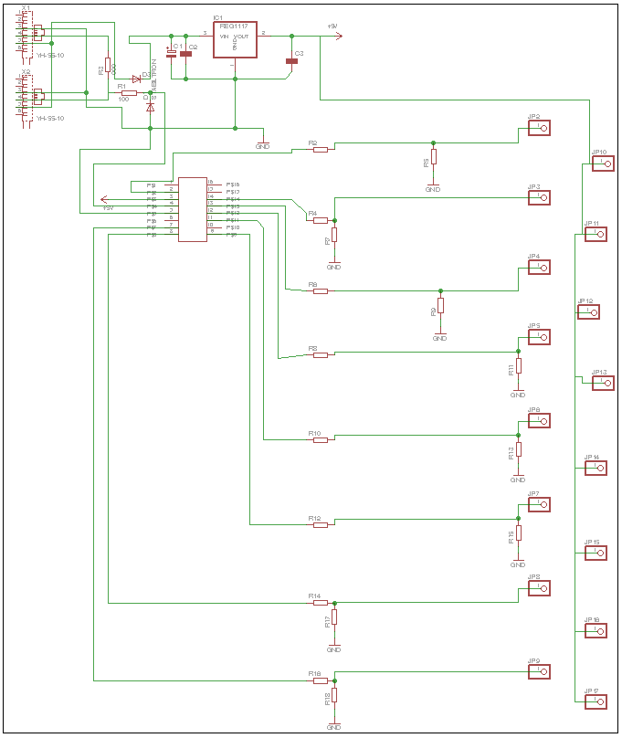
Pay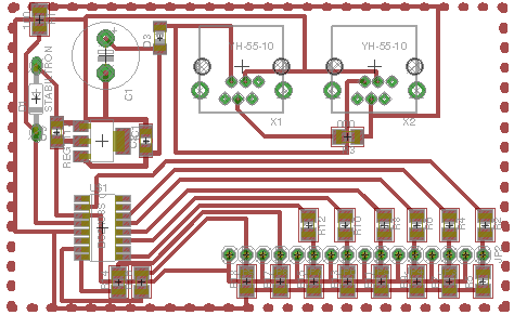
When I started messing around with the DS2408, I got the idea to make one combined board per room. Depending on the needs of a particular room in control systems, one board is distributed on the DS2408 where some of the contacts are responsible for managing the load, and some for reading the data. For example, for the bathroom and the nursery, boards were made with the ability to control two sources and read data from six.
Scheme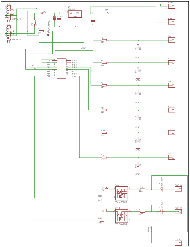
Pay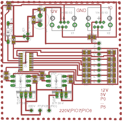
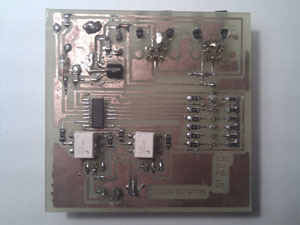
Appearance of the finished board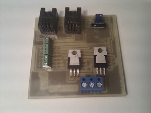
Two control outputs are the first and second group of light bulbs. Two readers are data from two switches, one motion sensor, one door sensor, two in reserve.I want to note that there is one serious shortcoming in this board, which complicates installation and maintenance. I brought to the terminals only one pin 5V, 12V, GND, and, for example, contacts 5V, are needed in each sensor. I had to connect several wires to one, which is inconvenient and unreliable.
Constructor
Experienced readers already know this, and attentive, probably, have already noticed that all schemes have some common modules. Actually, having understood this, one can quite easily design a chamber for one’s own needs, knowing, in essence, only a course of electricity from the school curriculum.
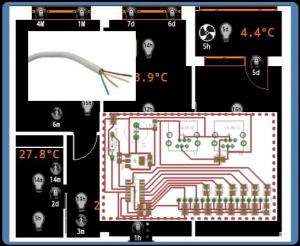
Let's analyze in detail on the basis of my last board, since it contains all these conditional modules.

- Connectors
- Power module
- Chip 1-wire with strapping
- Reading module
- Control module
Connectors
You can just draw conclusions to the board and hang up the connectors on the wires (in the purchase cards it was exactly like that), but it seemed to me not very convenient, and in the following boards I soldered these:
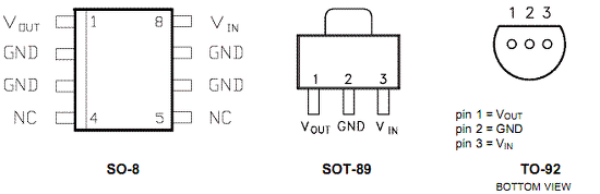
Power module
The main component here is the 78L05 chip, a wonderful thing that, from any input voltage in the range from 7V to 20V, gives us the necessary 5V.
It happens in different cases, it just so happened that there were always different types available and I had to use all types.
- Vin - 12V
- GND - land
- Vout - to board power
The auxiliary elements are fitted with a piping of capacitors (two solid-state and one electrolytic) for stabilization.
Chip 1-wire with strapping
The chip itself.
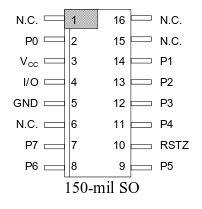
In this case, the DS2408 is connected as follows:
- Leg 3 - 5V
- Leg 4 - to 1-wire bus
- Leg 5 - land
- Legs 2, 7, 8, 9, 11, 12, 13, 14 - bidirectional input / output, that is, the very legs to which the reading or control modules are connected, depending on what we need
The pull-up resistor and the zener diode were on the source board and in the documentation for the chip, I do not know their exact purpose.
Reading module
It's actually just contacting the legs with a connector for ease of installation plus a pull-up resistor (without it, even very weak pickups can generate enough voltage for a false positive)
Control module
It consists of two main elements: the optocoupler MOC3043M and the simistor BT138.
The optocoupler is needed for electrical isolation (so that the 220V network is not connected in any way and does not affect the control network).
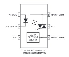
- Leg 1 - 5V
- Leg 2 - to exit 1-wire
- Leg 4 - to the triac
- Leg 6 - 220V
Principle of operation: when the value 1 appears in the corresponding register of DS2408, the corresponding leg is connected to ground. In the circuit from the leg 1 to the leg 2, a current begins to flow, a diode lights up inside, and closes the circuit between the legs 4 and 6, applying voltage to the triac.
A triac is needed to control the load with AC power, since the optocoupler itself cannot hold a high load.
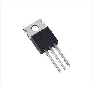
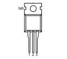
- Leg 1 - 220V
- Leg 2 - load output
- Leg 3 - from optocouplers
The principle of operation is similar to that of a transistor in a circuit with direct current, when voltage is applied to leg 3, the circuit between legs 1 and 2 is closed
Door and window opening sensors
As I wrote earlier, as opening sensors, I used unmarked Soviet reed switches plus neodymium magnets of 1x10 mm.
The wiring diagram is simple to ugliness, one contact per 5V second per contact read on the board.
If I did not have reed switches with magnets, I would buy, for example, such sensors:

In fact, these are the same reed switches and magnets, only packed in a case.
Motion sensors.
As a motion sensor, you can use almost any security motion sensor, as long as it can be powered from 12V and switch 5V (and most of them). In stores, you need to ask the security sensor, since, if you say about lighting control, you will slip a sensor that 220V switches and is powered by them, and such a sensor, without dancing with a tambourine, cannot be connected to the system in question.
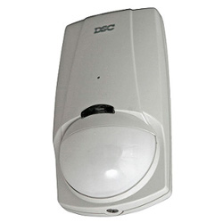
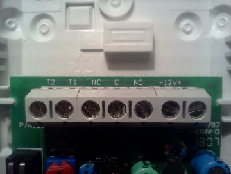
The sensors usually have seven contacts, for the needs of the smart home I used four of them
- T2, T1 - tamper contacts, which are responsible for unauthorized opening. In my case, I did not connect, as unnecessary.
- NC, C, NO - sensor contacts. I used normally open contact NO and C. They connect to 5V and read contact on the board, respectively.
- -12V + - sensor power supply. It's all clear.
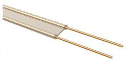
Leakage sensors
As the experiment showed, if two contacts (5V + contact reading from the board) are inserted into the water, the contact is considered closed, so it does not bother. The old Soviet telephone "noodles" with partially exposed (along the entire length from different sides) wires, and that's the whole leakage sensor.
Connecting classic switches
I have not taken root pushbutton switches (which are returned), because in rooms where there are several light sources with a group of switches and only a part is turned on, it is problematic to turn off the remaining ones, since the household does not have a logical connection to the button-lamp in the brain.
I have the usual keyboards. Down-> off, up-> on. If the light was previously turned on or off by a computer, you need to click back there. But in any case, if you need to turn off, then the end position of all switches at the bottom and vice versa.
The switch is connected to the gap between 5V and the readout contact on the board.
Backup power circuit
Let me remind you that the inclusion of light occurs as follows:
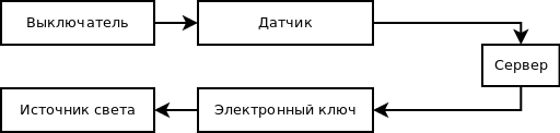
One of the main drawbacks of such a system with centralized control is that when the central node (server) fails, the control of the light becomes impossible. You can, of course, transfer the on / off logic to the board with the controller, but on the 1-wire base this is not possible. Therefore, for such emergency cases, I added a small switch connected in parallel with the electronic key. The switch is located on the case in which the board is packed. In the event of an accident (by the way, such an accident occurred immediately after the release of the first part of the article), you can forcibly close the circuit using a switch, this is certainly not very inconvenient, but the light is still present during the server repair.
CCTV
There is already no iron DIY, but probably worth mentioning.
For video capture, I used the cheapest, at that time, ORIENT SDVR-404 board.
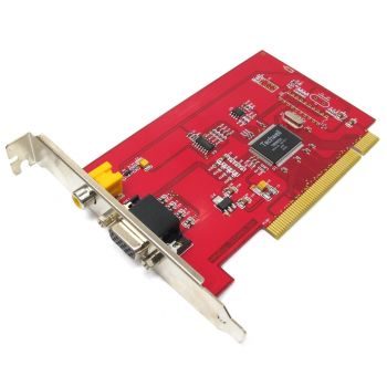
At that moment it seemed that more than one camera was not needed. There are three cameras now. And I’d better take a board with four processors instead of one.
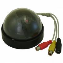
The cameras are Chinese noname, but, in principle, they are enough for my needs.
Conclusion
That's all iron. As you can see, nothing complicated, scary or mysterious. I hope my articles came in handy to you and may have made me build my system.
Special thanks to all those who wrote to me, asked questions and asked for the continuation, without you this part could not be.
Update:
Laid out source boards in github
github.com/sashacmc/smarthome-1wire
Update 2:
Continued here: Smart home, as I have come to this. Part 4
Source: https://habr.com/ru/post/198842/
All Articles