How to start making the engine control unit from scratch
About a year ago, I started developing a car engine control unit from scratch.
Let me tell you why this idea still seems realistic to me.
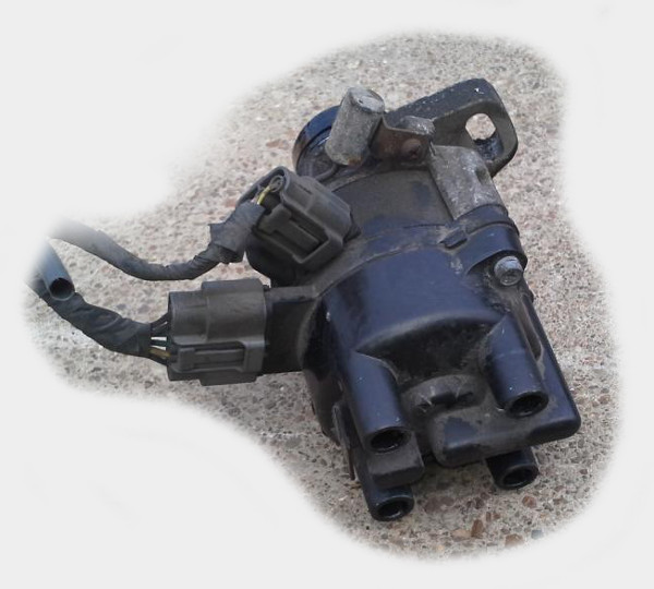
So, an old Kia Pride. Under the hood, she has such a thing, which is suitable for a dozen wires - this is the ignition distributor, in the case of which the camshaft position sensors and the ignition coil are integrated.
')
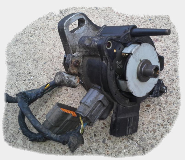
For a start, we are interested in shaft position sensors. If we start this dispenser a little to disassemble, inside we will see:
If we go a little further, we will see both the inner wheel and the sensors themselves.
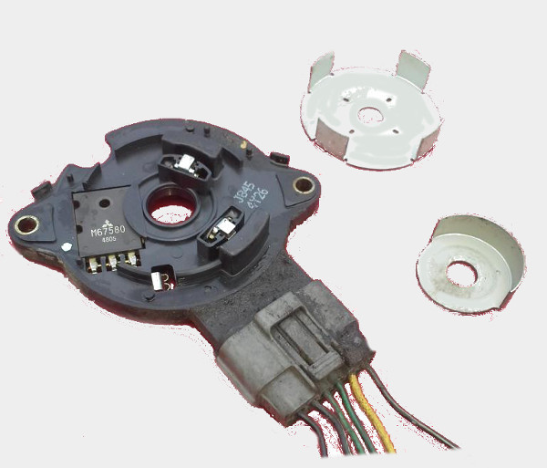
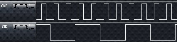
These two tin wheels sit on the shaft, rotate with it - and, oh, a miracle, they form a very simple signal in two wires sticking to the outside:
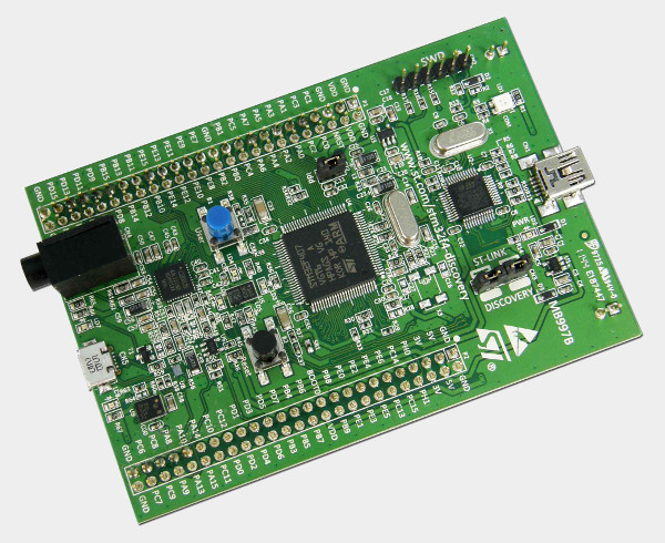
Our luck does not end there: although we know that a battery in a car is usually twelve volts - the signal electronics usually work at five volts! And this means that this signal can be absolutely connected as it is to stm32f4discovery for example - this is a board with a microcontroller, in which the price of less than a thousand rubles is combined with a 32-bit 168 MHz processor and even an arithmetic coprocessor.
If you decide to program this miracle using ChibiOS / RT, at least to simplify the interfaces for working with peripherals, then with such a simple code we will get a working tachometer into the console.
In my opinion, quite simply. But, nevertheless, it is one thing - to count something from the sensors, and quite another thing - to generate some kind of control signal.
Let's see how the nozzles are controlled?
In order not to experiment immediately with a large and iron engine, we’ll continue only with the original control unit - even if we want to replace it with our own board with our own code, it will still be useful to collect more information. For example, it will be useful
collect information about the width of the control signal nozzles, depending on the engine speed.
So, take the control unit and put it on the table.

Is the battery in our car at 12 volts? the old ATX power supply is also 12 volts, and we use it to power the control unit for the duration of the experiments.

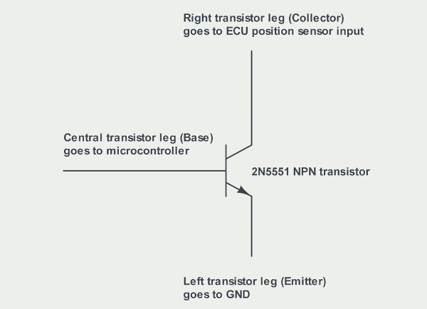
When we connected to the automotive wiring, we saw a five-volt signal there - but the crankshaft position sensor itself works like an open collector - i.e. the sensor wire is either grounded or not connected to anything. To emulate such a sensor, we will need a transistor.
And some code to generate a signal.
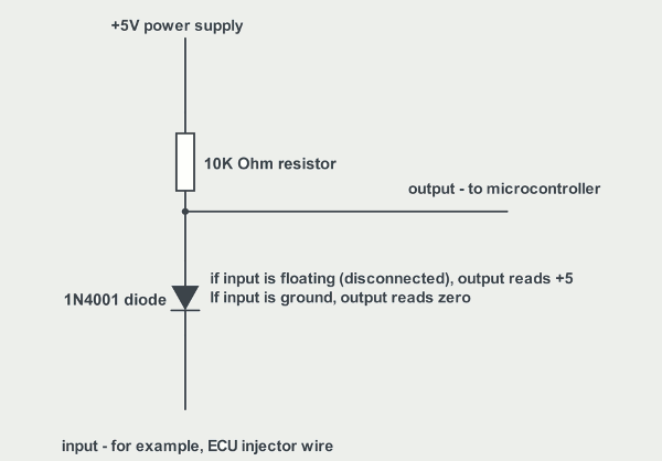
The fuel injection nozzles are controlled by grounding the wire coming to them from the control unit. To interpret such a signal from a block lying on the table, we need one diode and one resistor:
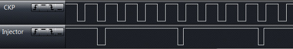
We collect it all and run. And, again, a miracle! The standard control unit believed us, and based on just one emulated sensor - the camshaft position sensor - began trying to control the injectors!
In fact, to get a meaningful fuel supply table, we will need to start emulating another air flow sensor. When we start managing these nozzles, we don’t have enough for a simple transistor to ground this roughly one-amp solenoid - but all of this is details. The main thing - to make the engine control unit from scratch seems real - so I continue to do it.
www.youtube.com/watch?v=GcxLY697WwM
update: once a question has arisen in the comments and since I have already given a link in the comments - I will add here too:
rusefi.com
rusefi.com/forum
sourceforge.net/projects/rusefi
Let me tell you why this idea still seems realistic to me.
So, an old Kia Pride. Under the hood, she has such a thing, which is suitable for a dozen wires - this is the ignition distributor, in the case of which the camshaft position sensors and the ignition coil are integrated.
')
For a start, we are interested in shaft position sensors. If we start this dispenser a little to disassemble, inside we will see:
If we go a little further, we will see both the inner wheel and the sensors themselves.
These two tin wheels sit on the shaft, rotate with it - and, oh, a miracle, they form a very simple signal in two wires sticking to the outside:
Our luck does not end there: although we know that a battery in a car is usually twelve volts - the signal electronics usually work at five volts! And this means that this signal can be absolutely connected as it is to stm32f4discovery for example - this is a board with a microcontroller, in which the price of less than a thousand rubles is combined with a 32-bit 168 MHz processor and even an arithmetic coprocessor.
If you decide to program this miracle using ChibiOS / RT, at least to simplify the interfaces for working with peripherals, then with such a simple code we will get a working tachometer into the console.
  volatile int rpm = 0;
 int lastInputEventTime = -10 * CH_FREQUENCY;

 void icuWidthCallback (ICUDriver * driver) {
     int now = chTimeNow ();
     int diff = now - lastInputEventTime;
     rpm = 60000 * TICKS_IN_MS * 2/4 / diff;
     lastInputEventTime = now;
 }

 ICUConfig wave_icucfg = {ICU_INPUT_ACTIVE_LOW, 100000, icuWidthCallback, NULL};

 int main (void) {
     halInit ();
     chSysInit ();

     // this thread would blink
     chThdCreateStatic (blinkingThreadStack, sizeof (blinkingThreadStack), NORMALPRIO, blinkingThread, NULL);

     // serial-over-usb initialization
     usb_serial_start ();

     // configure input signal pin
     palSetPadMode (CRANK_INPUT_PORT, CRANK_INPUT_PIN, PAL_MODE_ALTERNATE (GPIO_AF_TIM2));

     // start input capture the RPM based on the timestamps
     icuStart (& CRANK_DRIVER, & wave_icucfg);
     icuEnable (& CRANK_DRIVER);

     while (TRUE) {
         // RPM value is updated by handler
         chprintf (& SDU1, "rpm:% d \ r \ n", rpm);
         chThdSleep (100);
     }

     return 0;
} |
In my opinion, quite simply. But, nevertheless, it is one thing - to count something from the sensors, and quite another thing - to generate some kind of control signal.
Let's see how the nozzles are controlled?
In order not to experiment immediately with a large and iron engine, we’ll continue only with the original control unit - even if we want to replace it with our own board with our own code, it will still be useful to collect more information. For example, it will be useful
collect information about the width of the control signal nozzles, depending on the engine speed.
So, take the control unit and put it on the table.
Is the battery in our car at 12 volts? the old ATX power supply is also 12 volts, and we use it to power the control unit for the duration of the experiments.
When we connected to the automotive wiring, we saw a five-volt signal there - but the crankshaft position sensor itself works like an open collector - i.e. the sensor wire is either grounded or not connected to anything. To emulate such a sensor, we will need a transistor.
And some code to generate a signal.
  static PWMConfig pwmcfg_slow = {10000, 1000, NULL, {{
 PWM_OUTPUT_DISABLED, NULL}, {PWM_OUTPUT_ACTIVE_LOW, NULL}, {
 PWM_OUTPUT_DISABLED, NULL}, {PWM_OUTPUT_DISABLED, NULL}},
 / * HW dependent part. * /
 0};

 int main (void) {
     halInit ();
     chSysInit ();

     // this thread would blink
     chThdCreateStatic (blinkingThreadStack, sizeof (blinkingThreadStack), NORMALPRIO, blinkingThread, NULL);

     // serial-over-usb initialization
     usb_serial_start ();

     pwmStart (PWM_SLOW, & pwmcfg_slow);
     palSetPadMode (GPIOB, 7, PAL_MODE_ALTERNATE (2));
     pwmEnableChannel (PWM_SLOW, 1, 600);

     while (TRUE)
         chThdSleep (100);

     return 0;
} |
The fuel injection nozzles are controlled by grounding the wire coming to them from the control unit. To interpret such a signal from a block lying on the table, we need one diode and one resistor:
We collect it all and run. And, again, a miracle! The standard control unit believed us, and based on just one emulated sensor - the camshaft position sensor - began trying to control the injectors!
In fact, to get a meaningful fuel supply table, we will need to start emulating another air flow sensor. When we start managing these nozzles, we don’t have enough for a simple transistor to ground this roughly one-amp solenoid - but all of this is details. The main thing - to make the engine control unit from scratch seems real - so I continue to do it.
www.youtube.com/watch?v=GcxLY697WwM
update: once a question has arisen in the comments and since I have already given a link in the comments - I will add here too:
rusefi.com
rusefi.com/forum
sourceforge.net/projects/rusefi
Source: https://habr.com/ru/post/198672/
All Articles