Creating a 1k / 4k intro for Linux, part 4
Good luck, my overly patient friends!
As very few of you remember, in the second part we stopped at the fact that we received a rectangle on the whole screen in some hundreds of bytes there, and now we have been facing the problem of filling the voids in our codes and hearts with creativity for a year and a half.
What can you draw with just two triangles? Square? Fractal? Flying through megaton power blast in the city center? Is there a limit to madness, where reality ends and reality begins? How to properly care for the rays, what to feed them and what to reflect about you will learn in the sudden continuation of the series of articles about de-making!

For the convenience of prototyping, I suggest using shadertoy.com , links with examples will lead to the same. Thus, even users of alternative operating systems can immerse themselves in all this wonderful things that will be here.
Yes, under Windows WebL, which we will use implicitly, for some reason everyone likes to implement through ANGLE, which is an addict and is famous for stealing complex shaders. Therefore, I recommend including the native OpenGL (in chrome: --use-gl = desktop at startup), otherwise, after the third or fourth example, everything will explode and hardly correspond to what is being discussed.
And yes, we need fairly powerful modern video cards, something like the GTX 4xx or HD 6xxx at a minimum (and by no means Intel, to laugh), otherwise there will be a filmstrip.
')
I won’t go into details of what shaders are, where they come from and why - this is a topic for a separate series of articles, which will not, lol - you just need to understand what we have to
In GLSL, among other things, there are vector and matrix types
I propose to do what else 10-15 years ago was considered an unattainable dream - ray tracing in real time. Modern video cards are so monstrously productive that they are.
The main idea - in order to determine the color of a pixel on the screen, we start a beam from it and look for which object it will rest on, then using knowledge of the object and the intersection point, we somehow calculate the illumination and form the desired color.
How can one determine if a ray intersects a particular object, and if so, at what point? You can, for example, write down the equation of intersection of the beam with the desired object and solve them analytically. It is easy to find that this method very quickly becomes rather cumbersome for anything more complex than a sphere or a plane. This is not good, we want to draw the landing of a flock of felines to Mars, so we will use another method, namely spherical tracing of distance functions.
The distance function is a function R3-> R, which returns the distance to the nearest geometry for each point in space. In practice, writing such functions even for simple figures is easier than analytic intersection. For example:
In addition, using such functions it is easy to make constructive geometry:
And transformations - it is enough to convert the input sampling vector at:
* - not strict f-distance, assessment
How to find the intersection of the beam with such a function? One simple and elegant solution is spherical tracing. The algorithm is as follows:
On GLSL, a simple trace function looks like this:
So, a simple marcher for a sphere with a radius of 1 at the origin of coordinates looks, for example, like this (visualization of the distance traveled):

Our sphere suspiciously hangs in the air, so let's put it on a plane, for example:

Now let's muddle the lighting, to start simple diffuse, without glare and frills.
In the simple Lambert model, it is assumed that the light incident on the surface is scattered in all directions evenly, and therefore the illumination of the point is proportional to the cosine of the angle between the normal and the direction to the light source. In addition, the illumination decreases as the square of the distance from the source. Well, about the colors of the source and the surface itself, you need not forget.
In code, it looks like this:
The normal to get is simple - this is just the gradient of our distance function:
Result:

Something is missing, isn't it? The sphere still seems to be hanging, and somehow dark.
In order for the eyes to be quite realistic and pleasant, you need to add two pieces: a shadow and a shadow under the shadow.
First, add ambeint-lighting, just adding something like
The undershadow shadow, also ambient occlusion, is an approximation of the effect from the real world, when the surface is partially obscured by photons flying from all sides, and not just from a light source.
In realtime tride graphics, there are many ways to obtain a similar effect of varying degrees of upwardness. In the technique used, the canonical approach is to operate the scene-space of data on the proximity of geometry — we take several steps along the normal and determine how close anything is that could obscure us. This is a pretty dirty hack (as, in general, everything that we do on this planet), but it looks pretty ok.
Here is the code:
The usual shadow is made even simpler - we just let the beam from a point into the light source and see if we are not rested in that along the way.
Pay attention that you cannot start exactly from that point, you have to retreat a little bit (homework: why?)
And finally, close up the black fog there so that the background with ambient lighting does not merge:
Total:

But it is still gray and monotonous. Let's make the ball and the plane be of a different color. And so that the ball had metal highlights.
Let's create for this the
We divide our world into functions that return the geometry of individual materials, and write the following function:
Now it’s enough to use the material in the lighting function, but not the color constant.
The final touch add glare. In general, specular flare is also a crutch-crutch, an attempt to simulate the real effect of light reflection from metals (honestly physically, this is difficult to do - all sorts of BRDFs start, rendering equations, Metropolis beam reeling and other heavy academic graphics, which I do not understand ), therefore, there is a stack of various methods for approximating this effect. Here we use the normalized Blinn-Phong method, which is reduced to the cosine of the angle between the normal and half-vector between the observer and the light source. Specular highlights are physically independent of the diffuse color of the material.
Long or short, here's the code:
Total:

Our ball does not reflect anything suspicious, let's ban it.
Add reflections to the material field, which defines the proportion of incident light that will be reflected in the observer.
Wrap up the trace in the reflection cycle:
We will add all sorts of additions to the scene, and here's how to draw an owl:

But this is all bad.
Bad, bad, bad.
All this could be drawn without the functions of the distance, and it would work even faster. So let's throw everything out and start drawing geometry from scratch.
But first you should make a small digression into the world of disorder.
Ideally smooth spheres and planes - it's all good, but too synthetic. The real world is irregular, imperfect and generally made of shit. Therefore, to get closer to him with your picture, you need to add a pinch of chaos to your taste.
To make a good noise as it should, we need to have a function that takes one parameter and generates a random number depending on this parameter. That is, for the same parameter values there should be the same number on the output. The standard GLSL library contains references to such functions noise, noise2, etc., but in practice they are not implemented by any manufacturer (homework: why?), Therefore they were even cut out in the most recent edition. So we have to write our noise.
The traditional approach is:
where 48737.3213 is just a random number that I have just blindly dialed with a cat on the numeric keypad. The guys on the Internet love to copy-paste a certain number and carry it around with them everywhere, but I haven’t come across an explanation for this.
Noise from vec2 can be obtained in this way:
These functions, as is clear from the name - as if the hash from the input number, and at the slightest change of this very number, their value changes significantly. For our purposes, we need to have a function whose value changes more smoothly. There are several ways to build such functions that can be based on hashes, the main ones are perlin noise, value noise, simplex noise.
On the Internet this season it is fashionable to make mistakes about the noise of Perlin and take it as the addition of several octaves of noise. Multi-octave noise, or fractal noise, is a completely separate technique that can be based not only on Perlin’s noise, but also on any other. Perlin's noise is built on the fact that we take an N-dimensional mesh and arrange random normalized gradients at its nodes (= just normalized random vectors), after which for each point of space we can determine in which grid size we find, calculate the scalar product with all nodes and n-linearly interpolate between these works. Linear interpolation can be replaced by more complex, for example, making the second derivative of the resulting noise smooth, if you need it for some reason. Here is the noise of Perlin. He is bulky and cool. After this two minutes of educational program, now you can also laugh at everyone else and turn up your nose:

Simplex and Perlin noise we will not use here because of their excessive computational complexity. For our modest goals of enslaving the universe, there is enough value noise - we take random values at the grid nodes and interpolate between them, like this:
Now the notorious fractal noise is obtained by simply summing up several octaves:
So we get the following visual representation of noise:

( secret bonus track-2 )
Using this source of chance, you can do anything. For example, draw a city.
The basic idea: let's beat the space into quarters-sectors, and for each sector, using its number-coordinates, we will extract from the chaos the parameters of the structure - dimensions, number of storeys, type.
Similarly, you can highlight, for example, windows - depending on the heights and position, we take a random number and, based on it, decide whether the lights are on in this “window” or not.
The position of the camera, the starry sky - all this also comes from the box with random values.
In general, I'm actually already just tired of writing this little bit poor text. Most likely even more than you are tired of reading it. So let's just look at ????? PROFIT and go to bed at last!
Attention, slide show on your video cards:

Now it remains to minimize the economy - remove a few comments, shorten the names of variables and functions, remove spaces, line breaks, lead to the form in which our framework from the second part expects (insert our variables instead of Shadertools) and can be released. Well, that is, it is impossible, because it is still full of bad taste and you need a designer who would programmers all the time.
In general, this homework is to make this shader run and see how many bytes the elf weighs with it. My preliminary estimate is 2..2.5Kb.
And, and the last thing: by a strange coincidence, I will suddenly today (Mon, 10.21.2013) talk about the same thing in a little more detail at the Novosibirsk State University (Novosibirsk State University) in the evening at 19:30 in aud. 223 new sports complex . You can not come because you already know everything, lol. Well, that is the opposite - come, polayvkodim!
In the previous series: music synthesis in the C programming language.
In the following series: unbiased path tracing of polygonal geometry in real time on OpenCL, probably.
As very few of you remember, in the second part we stopped at the fact that we received a rectangle on the whole screen in some hundreds of bytes there, and now we have been facing the problem of filling the voids in our codes and hearts with creativity for a year and a half.
What can you draw with just two triangles? Square? Fractal? Flying through megaton power blast in the city center? Is there a limit to madness, where reality ends and reality begins? How to properly care for the rays, what to feed them and what to reflect about you will learn in the sudden continuation of the series of articles about de-making!
Introduction
For the convenience of prototyping, I suggest using shadertoy.com , links with examples will lead to the same. Thus, even users of alternative operating systems can immerse themselves in all this wonderful things that will be here.
Yes, under Windows WebL, which we will use implicitly, for some reason everyone likes to implement through ANGLE, which is an addict and is famous for stealing complex shaders. Therefore, I recommend including the native OpenGL (in chrome: --use-gl = desktop at startup), otherwise, after the third or fourth example, everything will explode and hardly correspond to what is being discussed.
And yes, we need fairly powerful modern video cards, something like the GTX 4xx or HD 6xxx at a minimum (and by no means Intel, to laugh), otherwise there will be a filmstrip.
')
Introduction-2
I won’t go into details of what shaders are, where they come from and why - this is a topic for a separate series of articles, which will not, lol - you just need to understand what we have to
gl_FragColor color of the current pixel to the gl_FragColor variable depending on its coordinates are gl_FragCoord (in pixels) and the iGlobalTime time (this is a shader specific, in GLSL standard there is nothing about time, of course).In GLSL, among other things, there are vector and matrix types
vecN , matN and the standard library of all sorts of mathematical and not so functions. A crap for the curious (GL ES because the shader is WebGL, which is inherited from OpenGL ES 2.0).Realtime raytracing
I propose to do what else 10-15 years ago was considered an unattainable dream - ray tracing in real time. Modern video cards are so monstrously productive that they are.
The main idea - in order to determine the color of a pixel on the screen, we start a beam from it and look for which object it will rest on, then using knowledge of the object and the intersection point, we somehow calculate the illumination and form the desired color.
How can one determine if a ray intersects a particular object, and if so, at what point? You can, for example, write down the equation of intersection of the beam with the desired object and solve them analytically. It is easy to find that this method very quickly becomes rather cumbersome for anything more complex than a sphere or a plane. This is not good, we want to draw the landing of a flock of felines to Mars, so we will use another method, namely spherical tracing of distance functions.
From me to you
The distance function is a function R3-> R, which returns the distance to the nearest geometry for each point in space. In practice, writing such functions even for simple figures is easier than analytic intersection. For example:
- Ball:
length(at) - R - Plane:
dot(at,N) - D - Parallelepiped:
length(max(abs(at)-size), 0.)) - Cylinder (Y):
length(at.xz) - R
In addition, using such functions it is easy to make constructive geometry:
- Union:
min(f, g) - Intersection:
max(f, g)* - Subtraction:
max(f, -g)*
And transformations - it is enough to convert the input sampling vector at:
- Transfer:
at-vec3(pos) - Rotation and more:
at*mat3(< >)(for scaling, you should keep in mind that the returned distance must be scaled back)
* - not strict f-distance, assessment
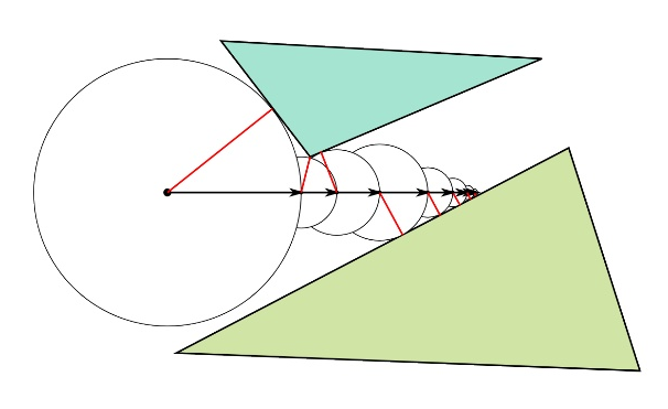
Spherical tracing
How to find the intersection of the beam with such a function? One simple and elegant solution is spherical tracing. The algorithm is as follows:
- We start the beam in direction D from point O.
- We obtain d equal to the value of the function at the point O
- Shift point O in direction D by distance d
- If d is greater than a certain selected threshold value, return to step 2.
- The current point O is the desired intersection with a given accuracy, we exit
On GLSL, a simple trace function looks like this:
float trace(vec3 O, vec3 D) { float L = 0.; for (int i = 0; i < MAX_STEPS; ++i) { float d = world(O + D*L); L += d; if (d < EPSILON) break; } return L; } So, a simple marcher for a sphere with a radius of 1 at the origin of coordinates looks, for example, like this (visualization of the distance traveled):
// , #define MAX_STEPS 32 #define EPSILON .001 // float world(vec3 a) { return length(a) - 1.; // 1 } // O D. float trace(vec3 O, vec3 D) { float L = 0.; // for (int i = 0; i < MAX_STEPS; ++i) { // MAX_STEPS float d = world(O + D*L); // L += d; // if (d < EPSILON*L) break; // , } return L; // } void main(void) { // [-1., 1.] vec2 uv = gl_FragCoord.xy / iResolution.xy * 2. - 1.; // uv.x *= iResolution.x / iResolution.y; // vec3 O = vec3(0., 0., 3.); // z ; -2. - vec3 D = normalize(vec3(uv, -2.)); // float path = trace(O, D); // , gl_FragColor = vec4(path * .2); } Our sphere suspiciously hangs in the air, so let's put it on a plane, for example:
float world(vec3 a) { return min(length(a) - 1., ay + 1.); } Now let's muddle the lighting, to start simple diffuse, without glare and frills.
In the simple Lambert model, it is assumed that the light incident on the surface is scattered in all directions evenly, and therefore the illumination of the point is proportional to the cosine of the angle between the normal and the direction to the light source. In addition, the illumination decreases as the square of the distance from the source. Well, about the colors of the source and the surface itself, you need not forget.
In code, it looks like this:
vec3 enlight(vec3 at, vec3 normal, vec3 diffuse, vec3 l_color, vec3 l_pos) { // vec3 l_dir = l_pos - at; // = // = (= ) // (= ) // , return diffuse * l_color * max(0.,dot(normal,normalize(l_dir))) / dot(l_dir, l_dir); } The normal to get is simple - this is just the gradient of our distance function:
vec3 wnormal(vec3 a) { vec2 e = vec2(.001, 0.); float w = world(a); return normalize(vec3( world(a+e.xyy) - w, world(a+e.yxy) - w, world(a+e.yyx) - w)); } Result:
Something is missing, isn't it? The sphere still seems to be hanging, and somehow dark.
In order for the eyes to be quite realistic and pleasant, you need to add two pieces: a shadow and a shadow under the shadow.
First, add ambeint-lighting, just adding something like
vec3(.1) or .2 to the color to your taste.The undershadow shadow, also ambient occlusion, is an approximation of the effect from the real world, when the surface is partially obscured by photons flying from all sides, and not just from a light source.
In realtime tride graphics, there are many ways to obtain a similar effect of varying degrees of upwardness. In the technique used, the canonical approach is to operate the scene-space of data on the proximity of geometry — we take several steps along the normal and determine how close anything is that could obscure us. This is a pretty dirty hack (as, in general, everything that we do on this planet), but it looks pretty ok.
Here is the code:
// float occlusion(vec3 at, vec3 normal) { // , float b = 0.; // for (int i = 1; i <= 4; ++i) { // .06 -- float L = .06 * float(i); float d = world(at + normal * L); // b += max(0., L - d); } // 1 return min(b, 1.); } The usual shadow is made even simpler - we just let the beam from a point into the light source and see if we are not rested in that along the way.
if (trace(at, normalize(l_dir), EPSILON*2.) < length(l_dir)) return vec3(0.); Pay attention that you cannot start exactly from that point, you have to retreat a little bit (homework: why?)
And finally, close up the black fog there so that the background with ambient lighting does not merge:
color = mix(color, vec3(0.), smoothstep(0.,20.,path)); Total:
Material values
But it is still gray and monotonous. Let's make the ball and the plane be of a different color. And so that the ball had metal highlights.
Let's create for this the
material_t structure: struct material_t { vec3 diffuse; float specular; }; We divide our world into functions that return the geometry of individual materials, and write the following function:
// material_t wmaterial(vec3 a) { // material_t m = material_t(vec3(.5, .56, 1.), 200.); float closest = s_ball(a); // -- float sample = s_floor(a); // if (sample < closest) { // closest = sample; // -- m.diffuse = vec3(1.-mod(floor(ax)+floor(az), 2.)); m.specular = 0.; } return m; } Now it’s enough to use the material in the lighting function, but not the color constant.
The final touch add glare. In general, specular flare is also a crutch-crutch, an attempt to simulate the real effect of light reflection from metals (honestly physically, this is difficult to do - all sorts of BRDFs start, rendering equations, Metropolis beam reeling and other heavy academic graphics, which I do not understand ), therefore, there is a stack of various methods for approximating this effect. Here we use the normalized Blinn-Phong method, which is reduced to the cosine of the angle between the normal and half-vector between the observer and the light source. Specular highlights are physically independent of the diffuse color of the material.
Long or short, here's the code:
if (m.specular > 0.) { // , , -- vec3 h = normalize(normalize(l_dir) + normalize(eye-at)); // color += l_color * pow(max(0.,dot(normal,h)), m.specular) * (m.specular + 8.) / 25.; } Total:
How about a wall of peas
Our ball does not reflect anything suspicious, let's ban it.
Add reflections to the material field, which defines the proportion of incident light that will be reflected in the observer.
Wrap up the trace in the reflection cycle:
// vec3 result_color = vec3(0.); // float k_reflectivity = 1.; for (int i = 0; i < MAX_REFLECTIONS; ++i) { // float path = trace(O, D, 0.); // , if (path < 0.) break; // , vec3 pos = O + D * path; vec3 nor = wnormal(pos); // material_t mat = wmaterial(pos); // vec3 color = .15 * (1. - occlusion(pos, nor)) * mat.diffuse; // color += enlight(pos, nor, O, mat, vec3(1., 1.5, 2.), vec3(2.*cos(t), 2., 2.*sin(t))); color += enlight(pos, nor, O, mat, vec3(2., 1.5, 1.), vec3(2.*sin(t*.6), 3., 2.*cos(t*.6))); // - color = mix(color, vec3(0.), smoothstep(0.,20.,path)); // result_color += k_reflectivity * color; // k_reflectivity *= mat.reflectivity; // , if (k_reflectivity < .1) break; // D = normalize(reflect(D, nor)); O = pos + D * EPSILON*2.; } We will add all sorts of additions to the scene, and here's how to draw an owl:
But this is all bad.
Bad, bad, bad.
All this could be drawn without the functions of the distance, and it would work even faster. So let's throw everything out and start drawing geometry from scratch.
But first you should make a small digression into the world of disorder.
Chaos theory
Ideally smooth spheres and planes - it's all good, but too synthetic. The real world is irregular, imperfect and generally made of shit. Therefore, to get closer to him with your picture, you need to add a pinch of chaos to your taste.
To make a good noise as it should, we need to have a function that takes one parameter and generates a random number depending on this parameter. That is, for the same parameter values there should be the same number on the output. The standard GLSL library contains references to such functions noise, noise2, etc., but in practice they are not implemented by any manufacturer (homework: why?), Therefore they were even cut out in the most recent edition. So we have to write our noise.
The traditional approach is:
float hash(float x) { return fract(sin(x)*48737.3213); } where 48737.3213 is just a random number that I have just blindly dialed with a cat on the numeric keypad. The guys on the Internet love to copy-paste a certain number and carry it around with them everywhere, but I haven’t come across an explanation for this.
Noise from vec2 can be obtained in this way:
float hash(vec2 x) { return hash(dot(x,vec2(71.,313.))); } These functions, as is clear from the name - as if the hash from the input number, and at the slightest change of this very number, their value changes significantly. For our purposes, we need to have a function whose value changes more smoothly. There are several ways to build such functions that can be based on hashes, the main ones are perlin noise, value noise, simplex noise.
On the Internet this season it is fashionable to make mistakes about the noise of Perlin and take it as the addition of several octaves of noise. Multi-octave noise, or fractal noise, is a completely separate technique that can be based not only on Perlin’s noise, but also on any other. Perlin's noise is built on the fact that we take an N-dimensional mesh and arrange random normalized gradients at its nodes (= just normalized random vectors), after which for each point of space we can determine in which grid size we find, calculate the scalar product with all nodes and n-linearly interpolate between these works. Linear interpolation can be replaced by more complex, for example, making the second derivative of the resulting noise smooth, if you need it for some reason. Here is the noise of Perlin. He is bulky and cool. After this two minutes of educational program, now you can also laugh at everyone else and turn up your nose:
Simplex and Perlin noise we will not use here because of their excessive computational complexity. For our modest goals of enslaving the universe, there is enough value noise - we take random values at the grid nodes and interpolate between them, like this:
// value noise float noise(vec2 x) { // F - , f - vec2 F = floor(x), f = fract(x); // vec2 e = vec2(1.,0.); // f *= f * (3. - 2. * f); // return mix( mix(hash(F+e.yy), hash(F+e.xy), fx), mix(hash(F+e.yx), hash(F+e.xx), fx), fy); } Now the notorious fractal noise is obtained by simply summing up several octaves:
// float fnoise(vec2 x) { // x += vec2(10.); // return .5 * noise(x) + .25 * noise(x*1.97) + .125 * noise(x*4.04) + .0625 * noise(x*8.17) ; } So we get the following visual representation of noise:
( secret bonus track-2 )
Destroying everything
Using this source of chance, you can do anything. For example, draw a city.
The basic idea: let's beat the space into quarters-sectors, and for each sector, using its number-coordinates, we will extract from the chaos the parameters of the structure - dimensions, number of storeys, type.
Similarly, you can highlight, for example, windows - depending on the heights and position, we take a random number and, based on it, decide whether the lights are on in this “window” or not.
The position of the camera, the starry sky - all this also comes from the box with random values.
In general, I'm actually already just tired of writing this little bit poor text. Most likely even more than you are tired of reading it. So let's just look at ????? PROFIT and go to bed at last!
Attention, slide show on your video cards:
Conclusion
Now it remains to minimize the economy - remove a few comments, shorten the names of variables and functions, remove spaces, line breaks, lead to the form in which our framework from the second part expects (insert our variables instead of Shadertools) and can be released. Well, that is, it is impossible, because it is still full of bad taste and you need a designer who would programmers all the time.
In general, this homework is to make this shader run and see how many bytes the elf weighs with it. My preliminary estimate is 2..2.5Kb.
And, and the last thing: by a strange coincidence, I will suddenly today (Mon, 10.21.2013) talk about the same thing in a little more detail at the Novosibirsk State University (Novosibirsk State University) in the evening at 19:30 in aud. 223 new sports complex . You can not come because you already know everything, lol. Well, that is the opposite - come, polayvkodim!
In the previous series: music synthesis in the C programming language.
In the following series: unbiased path tracing of polygonal geometry in real time on OpenCL, probably.
Source: https://habr.com/ru/post/198320/
All Articles