DIY dimmer for those who want it themselves
In the process of developing any project, many control points may change. Sometimes very dramatically. Today we decided to try to change one of such points of our project and publish the scheme and design of the PCB of the latest, product, revision of our DIY-dimmer. So that everyone who wants to be able to assemble our scheme and play with it now, without waiting for the appearance of ready-made beautiful boxes “for everyone” on the shelves.
For new ones, the previous series of our "series": the first , second and third . This is the fourth.
Changelog
The second revision of the board was able to become smaller both horizontally - 40x45mm and vertically - the estimated height is about 16mm without the case, with the case being about 18mm. Such dimensions will allow our modules to get into most of the wall boxes of this country.
')
Habrahabr spotted a startup in us and granted us his special corporate account . Who wants to follow the events around the project - subscribe to it, not all of our events will shine anywhere other than their corporate blog.
Our power unit developer has finally received a hafr-account alexfl and has already started responding to the hanging branches of comments about the details of the iron of the power unit. So now you can forget about the deaf telephones when I had to broadcast his answers to Habr.
In the process of minimizing the board, we had to switch to another, smaller type of modules NRF24LE1 with a pitch of 1.27 mm. With them there are some difficulties with the purchase. Gentlemen, the Chinese make such modules of different sizes with different distances between the tracks of the conclusions. The purchase guide will be published later so that no one is mistaken. And for those who still make a mistake, the power board is divorced in a cunning way so that you can also install a wide module too.
Also in the process of minimizing the GPIO had to be reduced. Now we display not all, but only one side of the module. What in any case should be enough for most applications. The conclusions themselves were also in 1.27 increments instead of the former 2.54 mm.
Thanks to the unexpected start of cooperation with MakeItLab, our project should accelerate significantly. We got at the disposal of several types of 3D printers, CNC machine tools, a lot of other interesting equipment, and most importantly, people interested in the development of the project who have time and desire to help. On the results of this cooperation I will make separate posts.
Circuit diagram

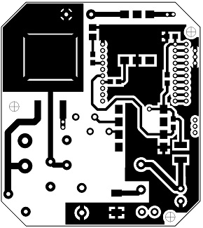
PCB Design
Upper side:
Down side:

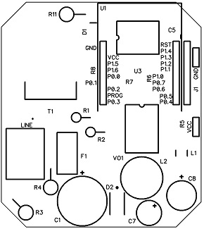
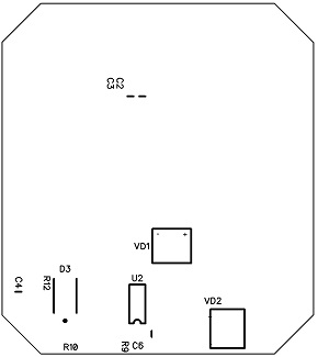
Arrangement of elements
Upper side:
Down side:
And at the end of the post
When submitting an application for registering a corporate account, we had to reveal all the cards - and the project name that had been invented a long time ago and the link to the site that was not yet completed. Therefore, we ask you to love and favor our name - CoolRF. You should not look at the site yet, nothing good has been posted there yet (a link to the project site was a mandatory requirement of the questionnaire).
And this is what the brand name of the module will look like, which we will use in the future:

Source: https://habr.com/ru/post/198316/
All Articles