We control the webcam with the joystick
Introduction
Lyrics
Good day. Motivated by numerous posts on Habré about self-made robots, he decided to do something more or less worthwhile and interesting.
In general, I have been fond of robots for a long time, but my hands did not reach the normal design, basically I was only playing. A little thought, invented his project, looked for details, drew sketches, fantasized about the future possibilities of the robot. I ordered the parts from a well-known site, and so far, the details are overcoming the path from the heavenly king decided to implement one of the modules of the future robot from what is at hand. Or rather, not to realize the module itself, but to assemble a prototype and write software, so as not to be distracted by writing a program, and even more so as long as all the details go there is a sea of free time, and the desire to do something does not give rest.
I had an Arduino Diecimila handkerchief, a few servo drives, a webcam, a joystick and an ultrasonic rangefinder on hand. Accordingly, immediately there was a desire to make a “computer vision” based on a webcam, with the possibility of both autonomous work and manual control (joystick).
What made me write this article?
Having rummaged in the Internet, I basically found all kinds of garbage, vague questions on the forums, excerpts from articles a bit far from needs. In general, I did not find a good, full-fledged article that would, from beginning to end, describe the creation of a moving webcam, with examples of code, and even more so combined with a range finder and joystick.
Then it was decided not to look for anything else, since the time for processing articles and collecting all the information in one became longer than if doing everything from scratch myself, especially since most of the articles are outdated for a long time.
')
The task is trivial, to send information from the joystick to the Arduino, which will rotate 2 servo drives with a fixed webcam at a certain angle, and, if necessary, read information from a rangefinder, sending it to SerialPort.
Having considered everything once more, I decided to start creating this prototype myself. Go!
Main part
Prototype build
The prototype was created within 5 minutes. The appearance of the prototype does not interest at all, its main goal is to work out the program part before the arrival of parts for the robot.
And I made it from the first available jar of some vitamins, two servo drives, a webcam, paper clips, electrical tape and a glue gun. It turned out the following:
A photo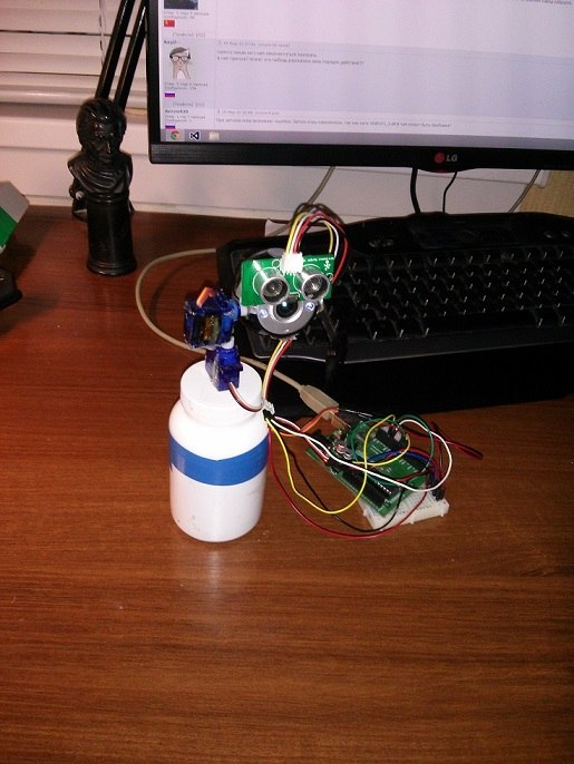
The assembly is completed, the servos and the ultrasonic rangefinder are connected to the Arduino, the Arduino to the PC, and we start programming the Arduino.
We program Arduino
It all seemed very simple, since the joystick connects to the PC, the main video processing will also be on the PC, the Arduino will only receive and process information from the PC and control the servo drives. Therefore, we only need to read the Serial Port, process the incoming information in some way and somehow react to it.
Looking ahead a bit, I’ll say right away that there was an error, which I had to return to after writing a program in C #. The error was this: I, naive and full of enthusiasm, wrote a program that parses a line of the following type “90:90” coming into the Serial Port into two parts, respectively, the first part is the degrees along the X coordinate, the second part Y. With the help of the monitor the port everything was tested and worked perfectly, but when the program for controlling the joystick was written, with an enhanced port attack with strings with varying values, the Arduino simply did not have time to read everything sequentially, therefore often the lines turned into “0: 909”, “: 9090" and the like ok
Accordingly, the servos went crazy and assumed all positions except those that we need.
Therefore, without hesitation, I came to the conclusion that we need a line start character and a line end character. Again, without hesitation, the first character of the Latin alphabet, “a,” was chosen by the beginning of line symbol, the last by the end of the line was “z”, and the characters for the beginning of the axis values were “x” and “y”, respectively. Total input line took the following form: "ax90y90z".
All is good, if not for the range finder. Ultrasonic range finder, he determines the distance with a bang, but there are several nuances. First, if the angle between the range finder and the wall is sharper than 45 degrees (plus or minus), then the sound is reflected from the wall on a tangent, and the value does not correspond to reality. Secondly, a rather large angle of signal emission, about 30 degrees (according to the manual), and the distance to the nearest object is measured, since the signal from the objects to which the sensor is at an angle is reflected to the other side, and we get a less real distance in a straight line , but interference still occurs, and quite often. Therefore, I added another function that takes n distance measurements, adds them and divides them into a count, set n = 10, so the noise became more smooth and less noticeable.
The code on the Arduino was immediately rewritten and took the following form:
Arduino code
#include <Servo.h> #include <String.h> /* ax180y180z a - x - x y - y z - */ String str_X=""; String str_Y=""; int XY_Flag=0; // 1 = X, 2 = Y Servo X_Servo; Servo Y_Servo; const int distancePin = 12; const int distancePin2 = 11; void setup() { Serial.begin(115200); X_Servo.attach(7); Y_Servo.attach(8); } void loop() { delay(50); if(Serial.available()>0) // { int inChar=Serial.read(); // if(inChar == 97) { // while(Serial.available()>0) { inChar=Serial.read(); // if(inChar==120){ // x XY_Flag=1; continue; } if(inChar==121){ // y XY_Flag=2; continue; } if(inChar==122){ // z ( ) XY_Flag=0; } if(XY_Flag==0) break; // , if(XY_Flag==1) str_X +=(char)inChar; // X, X if(XY_Flag==2) str_Y +=(char)inChar; // Y, Y } if(XY_Flag==0) // , ... { servo(str_X.toInt(), str_Y.toInt()); str_X=""; str_Y=""; // Serial.println("d" + String(trueDistance()) + "z"); } } } } void servo(int x, int y){ // :) X_Servo.write(x); Y_Servo.write(y); } long trueDistance() // n { int n=10; long _value=0; for(int i =0; i<n; i++) _value += distance(); return _value/n; } long distance() // { long duration, cm; pinMode(distancePin, OUTPUT); digitalWrite(distancePin, LOW); delayMicroseconds(2); digitalWrite(distancePin, HIGH); delayMicroseconds(10); digitalWrite(distancePin, LOW); pinMode(distancePin, INPUT); duration = pulseIn(distancePin, HIGH); cm = microsecondsToCentimeters(duration); return cm; } long microsecondsToCentimeters(long microseconds) // { return microseconds / 29 / 2; } The problem with the incorrect analysis of coordinates disappeared at all, 100 out of 100 tests were passed successfully.
The main control program (C #)
At first I wanted to write everything in C ++ under Qt, but later I still had to write in C #, but oh well.
What I wanted to get:
1. Face recognition
2. Tracking the face of a person.
3. Manual control with joystick.
4. Determination of the distance to the object.
For face recognition and image output from the webcam, without any questions, the OpenCV library was chosen, or rather its shell for C # - Emgu CV.
To read the position of the joystick at first, the Microsoft.DirectX.DirectInput library was used, which I did not like very much, and I applied the SharpDX library, and quite successfully.
What was required of the program:
1. Capture an image from a webcam and display it on the screen.
2. Recognize faces on the image, trace them and get the coordinates of the face on the image.
3. Form a string like “ax90y90z” and send it to the Serial Port to control the servos.
4. Read the position values of the joystick.
5. Read from a range finder.
Having formulated the tasks, we proceed to programming.
The SharpDX library allows us to find the connected joystick and receive axis values (from 0 to 65535), pressing and releasing the joystick keys from it. Servos can be rotated from 0 to 180 degrees, respectively, you need to convert the values of the joystick axes from 0 to 180. I just divided the return value by 363, and I got the output values from 0 to 180. Then I wrote a function that forms the servo position string and sends it to port.
Image output and face recognition are written using OpenCV and do not represent anything complicated (for us).
It is more interesting, having a range finder at hand, of course, I wanted to make a radar, and build at least some approximate picture of the terrain.
After repeating trigonometry and vectors, I wrote a procedure that calculates the coordinates of a point relative to our rangefinder with the camera on the angle of rotation of the servo drive and the distance to the object, and draws the results in PictureBox, I launch the procedure in the stream using the button, everything works, but still because of the room relief quite large interferences are obtained, but the approximate outline coincides with reality. I tried to smooth the data from the sensor, choosing only peak values and drawing intervals between them, in principle, it turned out not bad, but decided to abandon it, because often the interference values become peaks.
Code (just in case with detailed comments, if possible):
Form class
Capture myCapture; private bool captureInProgress = false; string _distance = "0"; string coords; int X_joy = 90; int Y_joy = 90; SerialPort _serialPort = new SerialPort(); Image<Bgr, Byte> image; DirectInput directInput; Guid joystickGuid; Joystick joystick; Thread th; private int GRAD_TURN_X = 2; private int GRAD_TURN_Y = 2; private void GetVideo(object sender, EventArgs e) { myCapture.FlipHorizontal = true; image = myCapture.QueryFrame(); try { // Image<Gray, Byte> gray = image.Convert<Gray, Byte>().Canny(100, 60); // CamImageBoxGray.Image = gray; } catch { } /* */ if (FaceCheck.Checked) { List<System.Drawing.Rectangle> faces = new List<System.Drawing.Rectangle>(); DetectFace.Detect(image, "haarcascade_frontalface_default.xml", "haarcascade_eye.xml", faces); foreach (System.Drawing.Rectangle face in faces) { image.Draw(face, new Bgr(System.Drawing.Color.Red), 2); int faceX = face.X + face.Width / 2; int faceY = face.Y + face.Height / 2; if ((faceX - 320 > 120) || (faceX - 320 < -120)) // , GRAD_TURN_X = 4; else if ((faceX - 320 > 80) || (faceX - 320 < -80)) GRAD_TURN_X = 3; else GRAD_TURN_X = 2; if ((faceY - 240 > 120) || (faceY - 240 < -120)) GRAD_TURN_Y = 4; else if ((faceY - 240 > 80) || (faceY - 240 < -80)) GRAD_TURN_Y = 3; else GRAD_TURN_Y = 2; label7.Text = faceX.ToString(); label8.Text = faceY.ToString(); if (!JoyCheck.Checked) { if (faceX > 370) X_joy += GRAD_TURN_X; else if (faceX < 290) X_joy -= GRAD_TURN_X; if (faceY > 270) Y_joy -= GRAD_TURN_Y; else if (faceY < 210) Y_joy += GRAD_TURN_Y; serialPortWrite(X_joy, Y_joy); } } } /*=============*/ System.Drawing.Rectangle rect1 = new System.Drawing.Rectangle(305, 240, 30, 1); System.Drawing.Rectangle rect2 = new System.Drawing.Rectangle(320, 225, 1, 30); System.Drawing.Rectangle rect3 = new System.Drawing.Rectangle(0, 0, 640, 22); image.Draw(rect1, new Bgr(System.Drawing.Color.Yellow), 1); image.Draw(rect2, new Bgr(System.Drawing.Color.Yellow), 1); image.Draw(rect3, new Bgr(System.Drawing.Color.Black), 22); MCvFont f = new MCvFont(FONT.CV_FONT_HERSHEY_TRIPLEX, 0.9, 0.9); image.Draw("Distance: " + _distance + " cm", ref f, new System.Drawing.Point(0, 30), new Bgr(0, 255, 255)); CamImageBox.Image = image; if (JoyCheck.Checked) { th = new Thread(joy); // , th.Start(); } label1.Text = X_joy.ToString(); label2.Text = Y_joy.ToString(); label3.Text = coords; } private void ReleaseData() { if (myCapture != null) myCapture.Dispose(); } public Form1() { InitializeComponent(); } private void serialPortWrite(int X, int Y) // { try { coords = "ax" + X + "y" + Y + "z"; _serialPort.Write(coords); _distance = _serialPort.ReadLine(); if (_distance[0] == 'd') if (_distance[_distance.Length - 2] == 'z') { _distance = _distance.Remove(_distance.LastIndexOf('z')).Replace('d', ' '); } else _distance = "0"; else _distance = "0"; } catch { } } private void joy() // { joystick.Poll(); var datas = joystick.GetBufferedData(); foreach (var state in datas) { if (state.Offset.ToString() == "X") X_joy = 180 - (state.Value / 363); else if (state.Offset.ToString() == "Y") Y_joy = state.Value / 363; } serialPortWrite(X_joy, Y_joy); } private void Form1_Load(object sender, EventArgs e) { if (myCapture == null) { try { myCapture = new Capture(); } catch (NullReferenceException excpt) { MessageBox.Show(excpt.Message); } } if (myCapture != null) { if (captureInProgress) { Application.Idle -= GetVideo; } else { Application.Idle += GetVideo; } captureInProgress = !captureInProgress; } _serialPort.PortName = "COM3"; _serialPort.BaudRate = 115200; if (_serialPort.IsOpen) _serialPort.Close(); if (!_serialPort.IsOpen) _serialPort.Open(); directInput = new DirectInput(); joystickGuid = Guid.Empty; foreach (var deviceInstance in directInput.GetDevices(DeviceType.Gamepad, DeviceEnumerationFlags.AllDevices)) joystickGuid = deviceInstance.InstanceGuid; if (joystickGuid == Guid.Empty) foreach (var deviceInstance in directInput.GetDevices(DeviceType.Joystick, DeviceEnumerationFlags.AllDevices)) joystickGuid = deviceInstance.InstanceGuid; joystick = new Joystick(directInput, joystickGuid); joystick.Properties.BufferSize = 128; joystick.Acquire(); } private void JoyCheck_CheckedChanged(object sender, EventArgs e) { if (FaceCheck.Checked) FaceCheck.Checked = !JoyCheck.Checked; } private void FaceCheck_CheckedChanged(object sender, EventArgs e) { if (JoyCheck.Checked) JoyCheck.Checked = !FaceCheck.Checked; } private void RadarPaint() { Bitmap map = new Bitmap(pictureBox1.Size.Width, pictureBox1.Size.Height); Graphics g = Graphics.FromImage(map); var p = new Pen(System.Drawing.Color.Black, 2); System.Drawing.Point p1 = new System.Drawing.Point(); System.Drawing.Point p2 = new System.Drawing.Point(); System.Drawing.Point p3 = new System.Drawing.Point(); System.Drawing.Point p4 = new System.Drawing.Point(); p1.X = pictureBox1.Size.Width/2 ; // p1.Y = pictureBox1.Size.Height; // pictureBox'a for (int i = 0; i < 181; i++) { serialPortWrite(i, 90); p2.X = Convert.ToInt32(Math.Ceiling(320 + int.Parse(_distance) * Math.Cos(i * Math.PI / 180))); // p2.Y = Convert.ToInt32(Math.Ceiling(480 - int.Parse(_distance) * Math.Sin(i * Math.PI / 180))); if (i > 0) g.DrawLine(p, p2, p3); if (i % 18 == 0) { p4 = p2; p4.Y -= 50; g.DrawString(_distance, new Font("Arial", 18), new SolidBrush(System.Drawing.Color.Red), p4); } p3.X = p2.X; p3.Y = p2.Y; g.DrawLine(p, p1, p2); try { pictureBox1.Image = map; } catch (Exception e) { MessageBox.Show(e.Message); } } } private void button1_Click(object sender, EventArgs e) { if (FaceCheck.Checked || JoyCheck.Checked) { FaceCheck.Checked = false; JoyCheck.Checked = false; } Thread t = new Thread(RadarPaint); t.Start(); } Class DetectFace
class DetectFace { public static void Detect(Image<Bgr, Byte> image, String faceFileName, String eyeFileName, List<Rectangle> faces) { CascadeClassifier face = new CascadeClassifier(faceFileName); // CascadeClassifier eye = new CascadeClassifier(eyeFileName); Image<Gray, Byte> gray = image.Convert<Gray, Byte>(); gray._EqualizeHist(); Rectangle[] facesDetected = face.DetectMultiScale( gray, 1.1, 5, new Size(70, 70), Size.Empty); faces.AddRange(facesDetected); } } As a result, we get everything we wanted. The computer recognizes faces and automatically tracks them. manual joystick control works with a bang. The radar, though not entirely accurate, but works. The main functions of the module of view of the robot are worked out and it remains only to refine and improve them.
Video
That's what happened at the end.
Conclusion
Results
It turned out pretty simple. The goal is achieved, the prototype is ready. There is something to work and do in your free time, waiting for a package with components for a robot.
Future plans
The next step will be building a wheel platform for the robot, setting up a remote control (WiFi, 3G)., Hanging sensors (temperature, pressure, etc.), speech synthesis. Wishlist also has plans for a mechanical hand.
I think if there is interest in this article and its continuation, then it will surely follow! Corrections and criticism are welcome!
Thanks for attention!
Source: https://habr.com/ru/post/198102/
All Articles