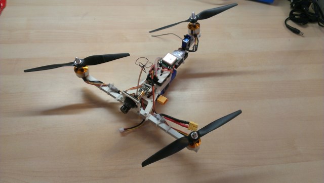
Lightweight FPV tricopter: development, assembly, configuration
A couple of months ago I wrote here about my heavy quad: one , two . Thanks to everyone who read and commented - I didn’t expect that my modest works would attract so many readers. But once this topic seems to be interested in Habr's audience, I’ll tell you about my latest project: a lightweight FPV tracker, which I completed just a few days ago.
For this copter, I set myself the following tasks:
')
Based on these requirements, I sat down again at LibreCad, and drew this:
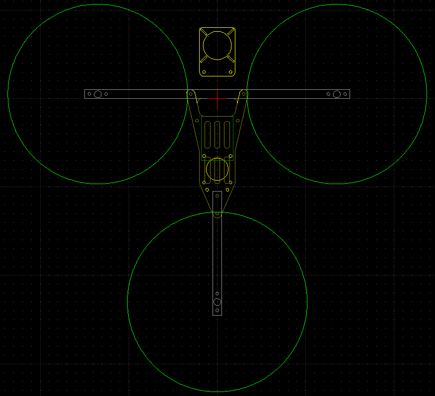
Dimensions: the distance between the front engines - 27 cm, diameter of the propellers - 8 ".
Trikopter is a rather rare type of multirotor. With only three propellers, it is impossible to compensate for the torque with pairs that rotate in the opposite direction, as is done on quad, hex, oct and other copters. In tricopters, instead, the tilt mechanism of the rear rotor is used, allowing it to deflect its thrust vector from the vertical and thus control the yaw. The advantages of this scheme for my project:
The disadvantage is increased mechanical complexity; a hinge is needed for mounting the rear motor, and a servo drive to control it.
I decided to assemble the frame from the aluminum profile and fiberglass plates cut on a milling machine. Aluminum gives absolutely sufficient rigidity on a copter of this size, and this design weighs very little. Then I picked up the following electronic components:
I reflashed the regulators with the SimonK firmware - it greatly improves the speed of the motor's reaction to the change of the set revolutions by the controller, it supports a high refresh rate of the input signal, and it is generally considered a must-have for the copters on the regulators that support it.
I didn’t find a suitable tilt mechanic for sale anywhere, and decided to do it myself - not long ago, access to a 3D printer was formed. Having dealt with FreeCAD over the evening, I drew the following details:
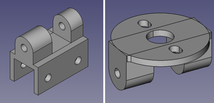
The result was a hinge with a fastening on a 10mm square tube, a hole for a 3mm axis, and a mount for a motor with standard openings.
My choice of controller for this copter also fell on a rather rare option - Naze32.
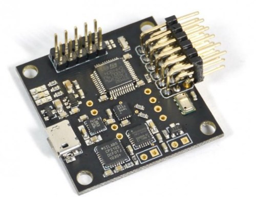
(pictured Flyduino MW32 clone used by me)
Naze32 is essentially a MultiWii port for modern hardware. A 32-bit STM32F103 processor, a MPU6050 gyro and accelerometer are used (the optional MMA8452 accelerometer is also installed, some software versions use it instead of MPU), the MS5611 barometer and the HMC5883L magnetometer. Why I chose this option:
I took the usual GPS receiver uBlox CN-06 (~ $ 50). It could have been limited to 10g more than the lightweight Mediatek module, but it is much slower and not so accurate - accuracy and update speed are critical for good performance of functions like return-to-home, therefore everywhere it is recommended to use uBlox.
First of all, I manufactured the plates for the frame and the mechanics of tilting the rear motor.
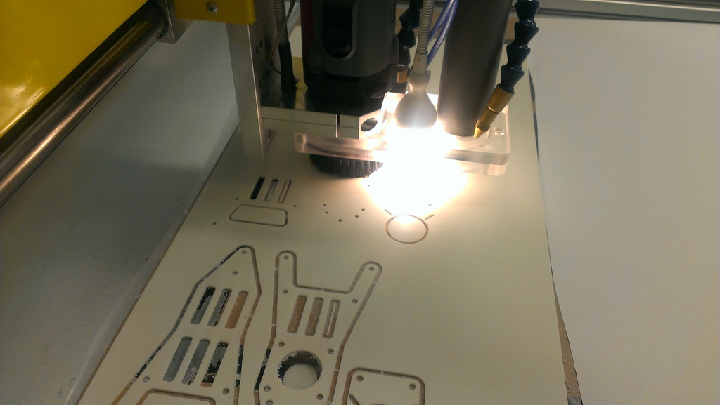
The milling machine cuts the plates along the contour. Below - the first failed attempt. Tip: if a 2 mm cutter is selected in the machine software, make sure that it is installed in the machine too :)
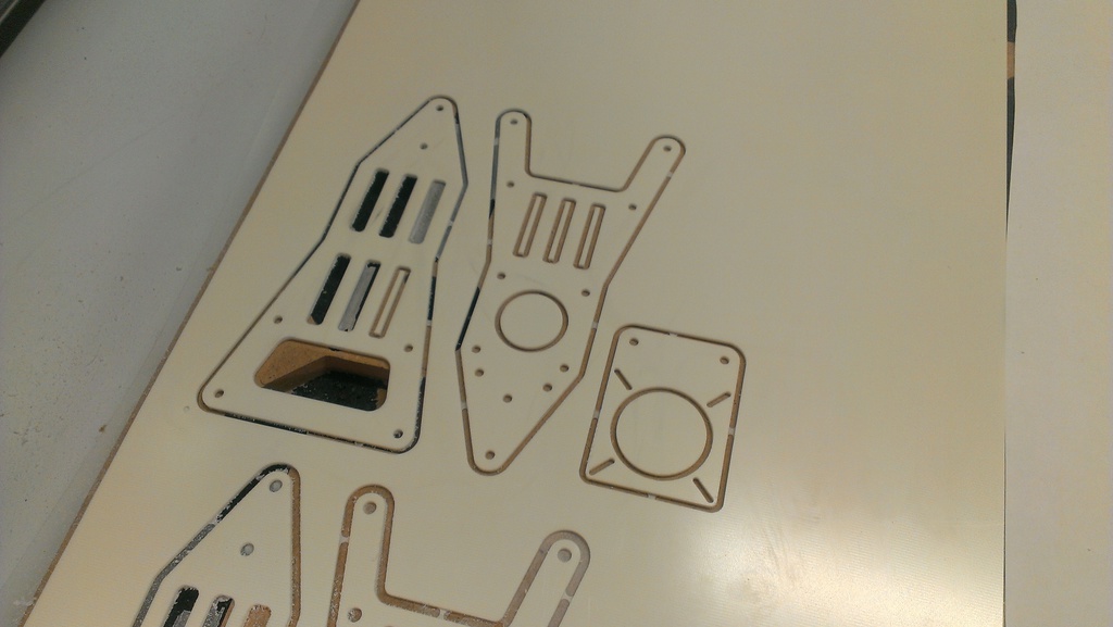
Main parts cut out
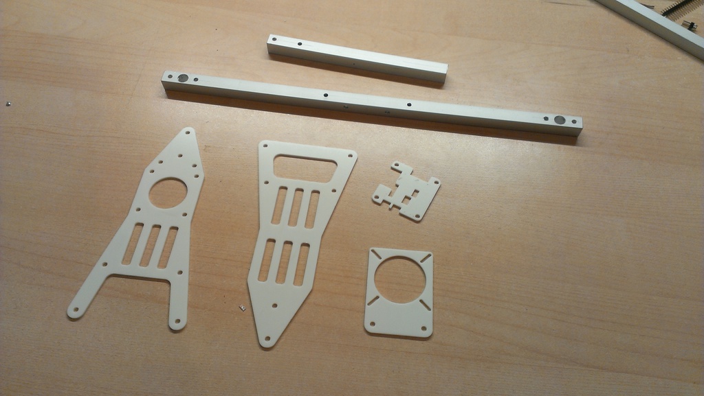
All parts are ready for assembly. Aluminum tubes are sawn to the desired length, all necessary holes are drilled.
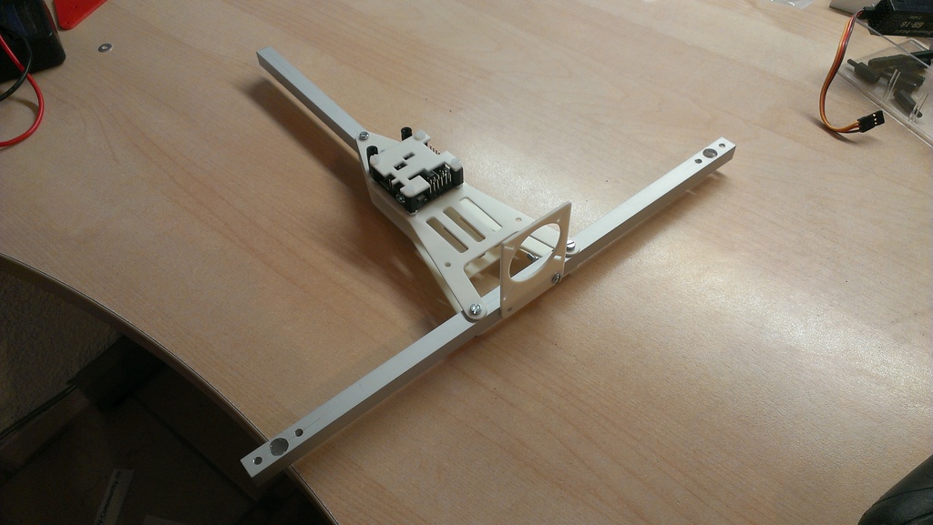
Assembled frame with controller.
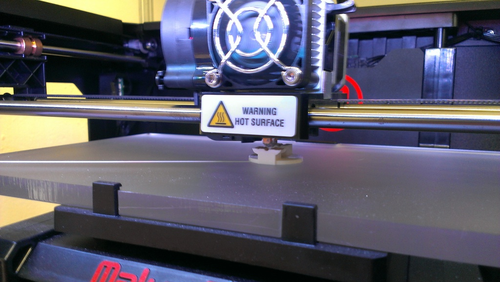
MakerBot Replicator 2 prints a PLA part. In total, printing of both halves took about 30 minutes, with a layer thickness of 0.2mm.
The finished halves of the hinge. The holes had to be re-drilled by hand, and the joint was machined with a file - but after that, the parts fit together perfectly, with virtually no backlash, and turn without effort.
Blue Series Regulators I, as mentioned above, have flashed SimonK software. For this, we had to remove the factory heat shrinkage from them, and using the USBAsp programmer , the adapter for Atmega chips and the kkflashtool program, they were reprogrammed. Since at that time I hadn’t assembled the frame yet and hadn’t unsoldered the cable, the test of the regulators after the firmware looked like
After that, I insulated the regulators with white heat shrink - since my frame is all white.
The final assembly of the copter in pictures:
Front motors, their adjusters and FPV camera are installed.
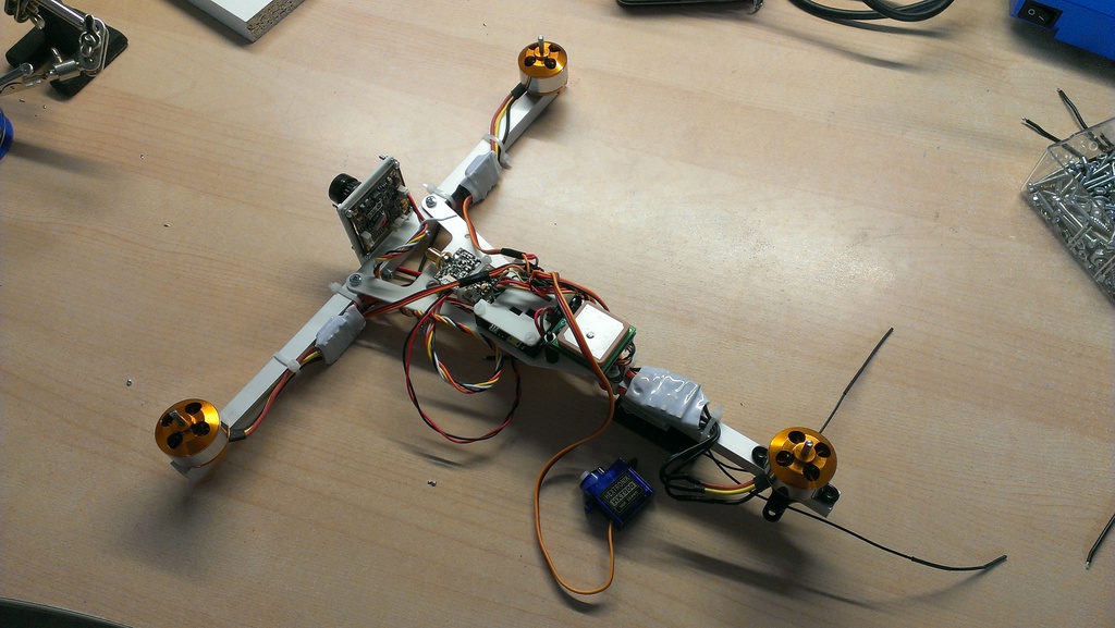
All the electronics are installed on the upper frame: a video transmitter in front, a controller on, a GPS and a regulator behind it, and a (still screwed) third motor. On the side is the servo.
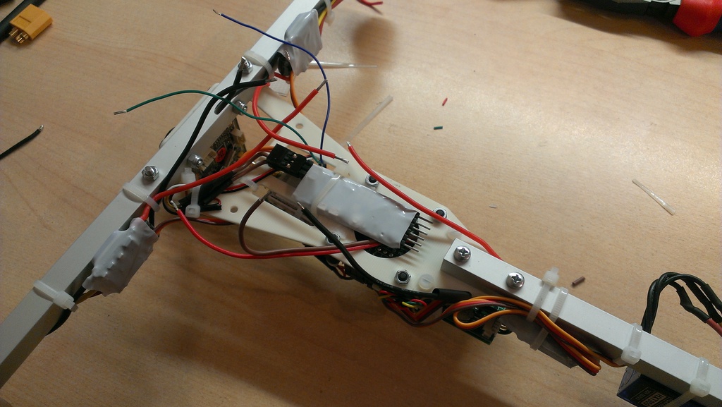
Bottom view: in the middle of MinimOSD in white shrink, around a bunch of wires.
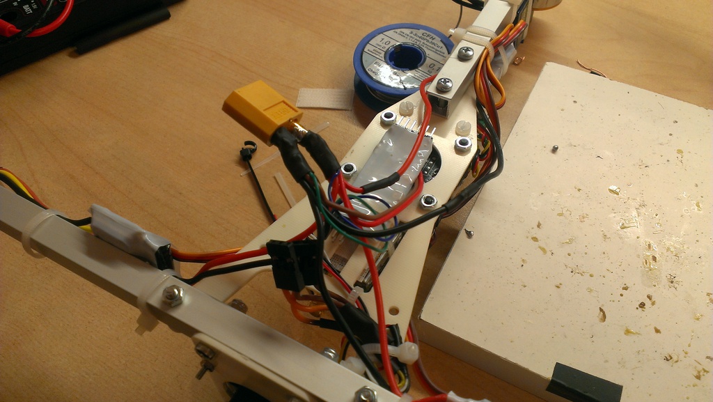
The pile of wires is slightly ordered, the battery connector is soldered (normal yellow XT60). What good are 3S batteries - their voltage of 11-12.6 V can directly feed 12-volt devices, in this case, the camera and the transmitter. Separate BECs are not needed, weight is saved.

Installed rear engine mechanics, servo and the motor itself. I took a 3mm carbon rod as the hinge axis, it is very light and durable. The holes for it are drilled in such a way that it sits tight in the upper half of the hinge, and rotates freely in the lower half. For peace of mind, it is also fixed with a drop of glue near the motor. Bottom hangs receiver d / y Graupner GR-16.

Ready kopter on kitchen scales. The old Turnigy batteries are 20 grams heavier than the new Zippy Compact, which I now fly on - so the final weight is now 550 grams, four times less than my quad.
However, the assembly of the copter is not everything.
Let's start with the most important - firmware controller software. With STM32 chips, everything is slightly more complicated than with Arduino-compatible MultiWii controllers, but not by much. Solder two contacts on the back of the controller, connect via USB and launch Flash Loader Demo :

We expose 115200 baud, the desired port, and go. Select “Next” several times, then select “Download”, mark “Jump to User Program” and “Global Erase”, select the downloaded hex file of the selected firmware (BaseFlight or Harakiri), and click Next again. After the firmware, the controller reboots, ready. Disable, remove the jumper between the contacts on the reverse side (otherwise the controller will be loaded each time in firmware mode).
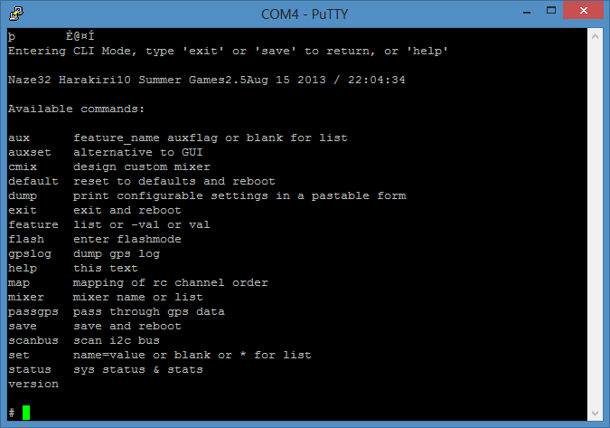
The software configuration is done in two steps - first, the basic parameters are configured via the command line, and then the standard interface from MultiWii is used to configure PID controllers, AUX channels and their ilk. Armed with Putty or any other terminal client, re-connect the controller to USB, open the connection to the serial port and immediately press "#" so that the controller enters the interactive mode:
We carry out the basic configuration - we set the type of the copter (a trikopter), turn on the GPS and PPM functions (if we use - PPM is the output mode of the signal from the d / y receiver, in which all channels are transmitted through one cable), set the channel map responsible for the four axes of control and AUX - it is different for different d / y systems). Save, the controller reboots.
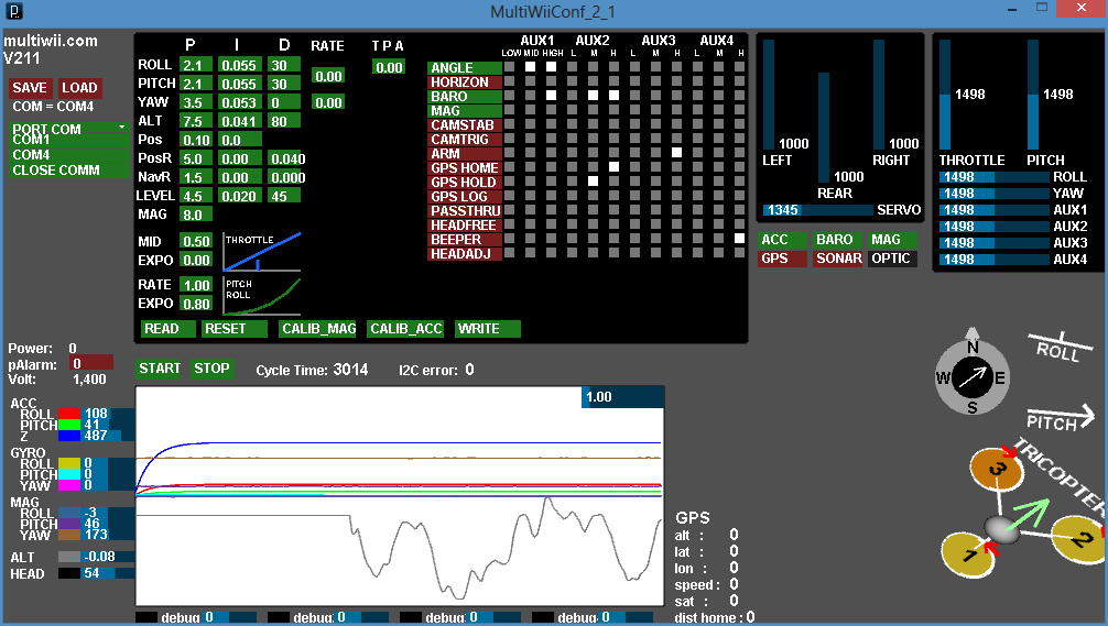
We close the terminal, and open MultiWii GUI 2.1. There, as with any ordinary MultiWii controller, we set the functions of the AUX channels, check the d / y channel ranges and adjust them so that the boundaries are as close as possible to 1000/2000 and the middle to 1500, we calibrate the accelerometer and magnetometer.
Everything, you can fly. The first test with a copter of such weight and size can be easily performed immediately on the spot, firmly holding it in your hand (generally I would not recommend this procedure, but at 550g of weight and ~ 1.4kg maximum thrust it is easy enough to hold): to start the motors at minimum gas and twist the rotor around all axes, checking that it reacts correctly (resists movement). If the servomotor tilts the rear motor in the wrong direction, this can be changed on the command line:
One more detail, because of which I had to dig out the parameters: the USB port on the Naze32 controller is located behind. When installed on my copter, however, there is a GPS, and the port is closed. So I decided to turn the controller 90 °. This is possible - you only need to change the axis of the sensors in the parameters; so that it is not too simple, the axes of the gyroscope, accelerometer and magnetometer are all different (even though the gyroscope and the accelerometer are combined in one chip). With the help of the FPV-Treff forum, we managed to find the right commands to rotate 90 ° clockwise:
They must be executed in this order, otherwise the controller may hang - apparently, there is a tricky bug somewhere hidden. After saving and rebooting, we are sure to check the correctness of the data in the MultiWii interface - the roll and pitch angle is shown on the right, they should now correspond to the position of the turned controller.
Since we are already doing a full-fledged FPV copter, then we cannot do without OSD, which shows information from the controller to the video. With Naze32, MinimOSD works great, with Harakiri even with standard firmware, since, unlike BaseFlight, Harakiri supports the MAVLink protocol. However, there is still such a great MinimOSD firmware called KV-Team-OSD . It is generally designed to work with MultiWii controllers, but works great with Naze32, and, unlike standard and other firmware, allows you to change the PID parameters of the controller using the remote control via the on-screen menu. This greatly reduces the time to configure these very parameters, which usually change only through the GUI on the computer.
MinimOSD is a miniature board with OSD chip MAX7456 and ATmega 328p processor, compatible with Arduino. For firmware and configuration, only an FTDI adapter is needed, since there is no USB connector on the board.
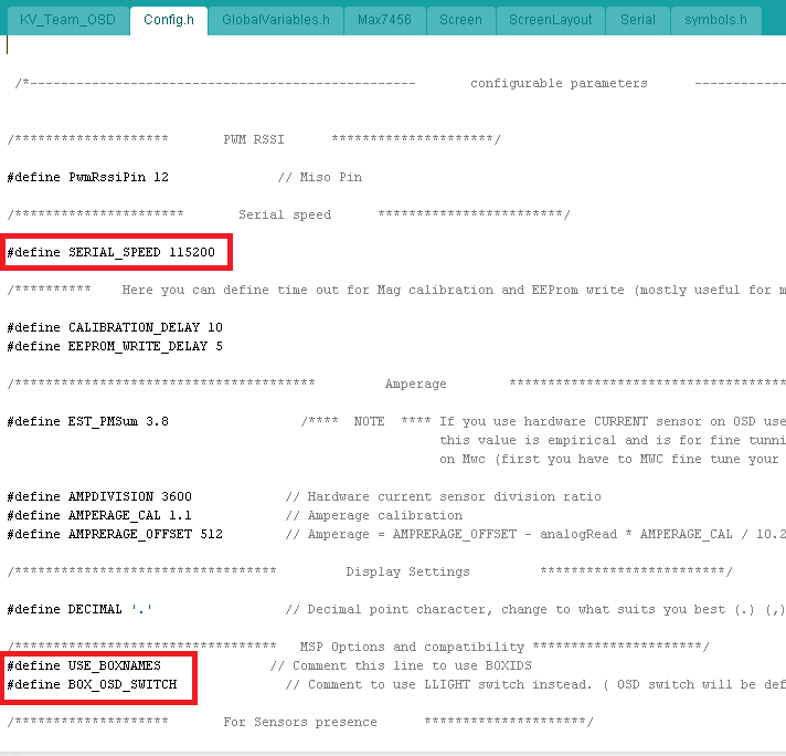
First we connect MinimOSD via FTDI to the USB port and open the Arduino. Open the standard sketch EEPROM Clear, select the desired COM port, set up the Arduino Pro or Pro Mini (5V, 16 MHz) w / ATmega 328 board, fill it up. We wait a couple of seconds until the LED on the board lights up - the memory of the old firmware is erased. Download the KV-Team-OSD version of r345 or r370, open and add the following lines to config.h:
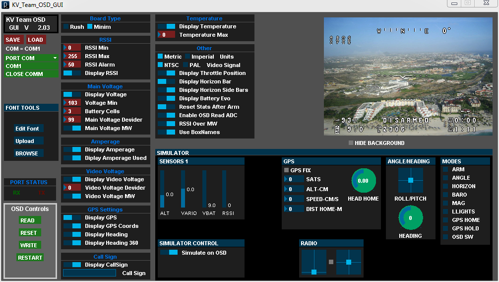
Compile, fill. We close the Arduino, connect the power to the OSD side of the board (they need 12V, otherwise the MAX7456 chip does not receive power; alternatively on some versions you can connect several contacts with solder and power the MAX7456 from 5V, then in no case can you connect + from the camera and transmitter ), and open the GUI from KV-Team-OSD. It is made on the same Processing as the MultiWii GUI, and looks accordingly similar. Fill the font on the MAX7456 chip by clicking Upload, waiting for the process to finish. We set the parameters: Minim board, do not show RSSI and other garbage, show voltage from MultiWii data (if we have the corresponding cable on the controller), show GPS data except coordinates, well, everything else is optional.
If at this moment the camera and the transmitter are already connected and powered up, then the video immediately by pressing Write shows changes in settings. For complete satisfaction, you can turn on the simulator in the GUI at the bottom and play around with the simulation, looking at how the OSD picture will change in flight.
After all the settings are completed, we don’t forget to press Write, disconnect the FTDI adapter and connect MinimOSD to Naze32 - the TX and RX pins are in the middle of the controller, + 5V and the ground can be taken directly from one of the BEC controllers, or from a free connector on the controller.
For the quality of the onboard video, I apologize in advance. Since there is only an FPV camera on the copter, the recording is carried out by a simple recorder at the base station - thus the recording quality is slightly worse than what I see with glasses during operation. But, unlike recording using GoPrO, OSD data is visible.
My first flight with a cheap HXT900 servos and imperfect PIDs is already quite good, but a little nervous. In the middle of the video you can see how I land and change the PID-parameters through the on-screen menu, after that the flight is much smoother. OSD does not work completely - I forgot one of the parameters in config.h (boxnames), because of this, the status of active sensors, flight mode, Armed / Disarmed status and GPS speed do not work.
Flight after installing the TGY-9025MG servos and reconfiguring PIDs. Plus OSD works completely. Much better :)
To summarize. All tasks assigned to the copter are completed:
I am satisfied with the device a little more than completely. To fly on it is a pleasure; Naze32 with Harakiri software flies superbly, the copter is very stable in the air and changes the direction of flight like a fly due to its light weight and fairly powerful motorization.
Since I am not an egoist, and I consider ideologically incorrect to leave such pleasure to myself, here are the links to the frame drawings and files for 3D printing of the hinge for everyone:
I will be glad to any comments, criticism and comments. I will try to answer the questions.
Task
For this copter, I set myself the following tasks:
')
- High maneuverability: although it’s impossible to call my quad unwieldy, nevertheless, with a weight of 2.2 kg and with an expensive camera on a relatively fragile suspension in the front, it is not possible to play the aerobatic maneuvers on the front. I wanted a kopter on which it would be possible to turn the barrels and hinges around the trees without any back thoughts.
- Shock resistance: the requirement is directly related to the first. It’s not a matter of fixing a copter after each unexpected planting in a tree, the device must take a hit.
- Flight time: at least 10-15 minutes, changing batteries more often is already not interesting.
- Lightweight: this requirement comes from the three previous ones. The lighter the copter, the easier it is for him to change the direction of flight, the less the energy of a collision with something, and the longer it sags in the air on one battery.
- Compactness: I wanted a device that fits in a backpack, so that you can easily take it with you in public transport and on hikes.
Based on these requirements, I sat down again at LibreCad, and drew this:
Dimensions: the distance between the front engines - 27 cm, diameter of the propellers - 8 ".
Why tricopter?
Trikopter is a rather rare type of multirotor. With only three propellers, it is impossible to compensate for the torque with pairs that rotate in the opposite direction, as is done on quad, hex, oct and other copters. In tricopters, instead, the tilt mechanism of the rear rotor is used, allowing it to deflect its thrust vector from the vertical and thus control the yaw. The advantages of this scheme for my project:
- Increased yaw maneuverability, which is the slowest and most inaccurate for ordinary copters.
- Weight reduction due to the use of only three motors
- The large distance between the front rotors allows you to place the camera so that the propellers will not come into view, not taking it away from the center of the copter
The disadvantage is increased mechanical complexity; a hinge is needed for mounting the rear motor, and a servo drive to control it.
Equipment
I decided to assemble the frame from the aluminum profile and fiberglass plates cut on a milling machine. Aluminum gives absolutely sufficient rigidity on a copter of this size, and this design weighs very little. Then I picked up the following electronic components:
| Motors: | Suppo A2208 / 17 1100KV | 3x € 13.95 |
|---|---|---|
| Propellers: | Flyduino HQ 8x5 CF-reinforced (Graupner E-Prop Clones) | € 7.80 |
| Regulators: | Blue Series 12A | 3x $ 10.02 |
| Battery: | Zippy Compact 3S 2200mAh 25C | $ 13.17 |
| Servo: | Turnigy TGY-9025MG | $ 5.04 |
| FPV camera: | Sony Super HAD II 600TVL | ~ $ 45 |
| FPV transmitter: | Iftrontech Nano Stinger 5.8G 25mw | ~ 100 $ |
| OSD: | MinimOSD | ~ $ 20 |
I didn’t find a suitable tilt mechanic for sale anywhere, and decided to do it myself - not long ago, access to a 3D printer was formed. Having dealt with FreeCAD over the evening, I drew the following details:
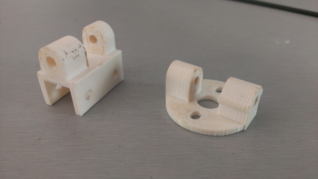
The result was a hinge with a fastening on a 10mm square tube, a hole for a 3mm axis, and a mount for a motor with standard openings.
Controller
My choice of controller for this copter also fell on a rather rare option - Naze32.
(pictured Flyduino MW32 clone used by me)
Naze32 is essentially a MultiWii port for modern hardware. A 32-bit STM32F103 processor, a MPU6050 gyro and accelerometer are used (the optional MMA8452 accelerometer is also installed, some software versions use it instead of MPU), the MS5611 barometer and the HMC5883L magnetometer. Why I chose this option:
- Computational power - most controllers are based on 8-bit ATMega chips, their power is no longer enough for many advanced functions, and in the future it will not become easier. I wanted a controller that will receive software updates with new features in the future, while not being limited to obsolete hardware.
- Open source software based on MultiWii - I decided to use fork of the basic Naze32 software (BaseFlight) called Harakiri, which is written on the German FPV-Treff forum. Being based on MultiWii, it is perfect for a lightly highly maneuverable copter, but it does not require fussing in the code (the entire configuration is done via the command line and standard MultiWii GUI) and perfectly supports GPS functions such as return home.
- Support for open communication protocols MultiWii and MAVLink - important for using MinimOSD.
- Last but not least - the size of the controller. All sensors are located on the 35x35mm board, with the absolute minimum of the necessary connectors - saving space and weight on an already small copter.
I took the usual GPS receiver uBlox CN-06 (~ $ 50). It could have been limited to 10g more than the lightweight Mediatek module, but it is much slower and not so accurate - accuracy and update speed are critical for good performance of functions like return-to-home, therefore everywhere it is recommended to use uBlox.
Preparation of parts
First of all, I manufactured the plates for the frame and the mechanics of tilting the rear motor.
Frame
The milling machine cuts the plates along the contour. Below - the first failed attempt. Tip: if a 2 mm cutter is selected in the machine software, make sure that it is installed in the machine too :)
Main parts cut out
All parts are ready for assembly. Aluminum tubes are sawn to the desired length, all necessary holes are drilled.
Assembled frame with controller.
Mechanics
MakerBot Replicator 2 prints a PLA part. In total, printing of both halves took about 30 minutes, with a layer thickness of 0.2mm.
The finished halves of the hinge. The holes had to be re-drilled by hand, and the joint was machined with a file - but after that, the parts fit together perfectly, with virtually no backlash, and turn without effort.
Regulators
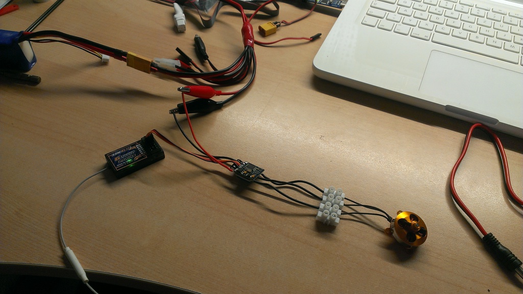
Blue Series Regulators I, as mentioned above, have flashed SimonK software. For this, we had to remove the factory heat shrinkage from them, and using the USBAsp programmer , the adapter for Atmega chips and the kkflashtool program, they were reprogrammed. Since at that time I hadn’t assembled the frame yet and hadn’t unsoldered the cable, the test of the regulators after the firmware looked like
After that, I insulated the regulators with white heat shrink - since my frame is all white.
Assembly
The final assembly of the copter in pictures:
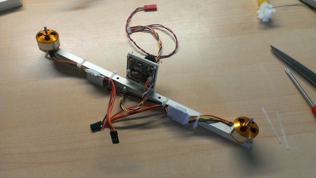
Front motors, their adjusters and FPV camera are installed.
All the electronics are installed on the upper frame: a video transmitter in front, a controller on, a GPS and a regulator behind it, and a (still screwed) third motor. On the side is the servo.
Bottom view: in the middle of MinimOSD in white shrink, around a bunch of wires.
The pile of wires is slightly ordered, the battery connector is soldered (normal yellow XT60). What good are 3S batteries - their voltage of 11-12.6 V can directly feed 12-volt devices, in this case, the camera and the transmitter. Separate BECs are not needed, weight is saved.
Installed rear engine mechanics, servo and the motor itself. I took a 3mm carbon rod as the hinge axis, it is very light and durable. The holes for it are drilled in such a way that it sits tight in the upper half of the hinge, and rotates freely in the lower half. For peace of mind, it is also fixed with a drop of glue near the motor. Bottom hangs receiver d / y Graupner GR-16.
Ready kopter on kitchen scales. The old Turnigy batteries are 20 grams heavier than the new Zippy Compact, which I now fly on - so the final weight is now 550 grams, four times less than my quad.
However, the assembly of the copter is not everything.
Naze32 firmware
Let's start with the most important - firmware controller software. With STM32 chips, everything is slightly more complicated than with Arduino-compatible MultiWii controllers, but not by much. Solder two contacts on the back of the controller, connect via USB and launch Flash Loader Demo :
We expose 115200 baud, the desired port, and go. Select “Next” several times, then select “Download”, mark “Jump to User Program” and “Global Erase”, select the downloaded hex file of the selected firmware (BaseFlight or Harakiri), and click Next again. After the firmware, the controller reboots, ready. Disable, remove the jumper between the contacts on the reverse side (otherwise the controller will be loaded each time in firmware mode).
BaseFlight / Harakiri configuration
The software configuration is done in two steps - first, the basic parameters are configured via the command line, and then the standard interface from MultiWii is used to configure PID controllers, AUX channels and their ilk. Armed with Putty or any other terminal client, re-connect the controller to USB, open the connection to the serial port and immediately press "#" so that the controller enters the interactive mode:
We carry out the basic configuration - we set the type of the copter (a trikopter), turn on the GPS and PPM functions (if we use - PPM is the output mode of the signal from the d / y receiver, in which all channels are transmitted through one cable), set the channel map responsible for the four axes of control and AUX - it is different for different d / y systems). Save, the controller reboots.
mixer tri feature gps feature ppm map TAER1234 save We close the terminal, and open MultiWii GUI 2.1. There, as with any ordinary MultiWii controller, we set the functions of the AUX channels, check the d / y channel ranges and adjust them so that the boundaries are as close as possible to 1000/2000 and the middle to 1500, we calibrate the accelerometer and magnetometer.
Everything, you can fly. The first test with a copter of such weight and size can be easily performed immediately on the spot, firmly holding it in your hand (generally I would not recommend this procedure, but at 550g of weight and ~ 1.4kg maximum thrust it is easy enough to hold): to start the motors at minimum gas and twist the rotor around all axes, checking that it reacts correctly (resists movement). If the servomotor tilts the rear motor in the wrong direction, this can be changed on the command line:
set yaw_direction = -1 One more detail, because of which I had to dig out the parameters: the USB port on the Naze32 controller is located behind. When installed on my copter, however, there is a GPS, and the port is closed. So I decided to turn the controller 90 °. This is possible - you only need to change the axis of the sensors in the parameters; so that it is not too simple, the axes of the gyroscope, accelerometer and magnetometer are all different (even though the gyroscope and the accelerometer are combined in one chip). With the help of the FPV-Treff forum, we managed to find the right commands to rotate 90 ° clockwise:
set align_mag_z = -2 set align_mag_y = -3 set align_mag_x = -1 set align_acc_z = 3 set align_acc_y = -2 set align_acc_x = -1 set align_gyro_z = -3 set align_gyro_y = 1 set align_gyro_x = -2 They must be executed in this order, otherwise the controller may hang - apparently, there is a tricky bug somewhere hidden. After saving and rebooting, we are sure to check the correctness of the data in the MultiWii interface - the roll and pitch angle is shown on the right, they should now correspond to the position of the turned controller.
OSD configuration
Since we are already doing a full-fledged FPV copter, then we cannot do without OSD, which shows information from the controller to the video. With Naze32, MinimOSD works great, with Harakiri even with standard firmware, since, unlike BaseFlight, Harakiri supports the MAVLink protocol. However, there is still such a great MinimOSD firmware called KV-Team-OSD . It is generally designed to work with MultiWii controllers, but works great with Naze32, and, unlike standard and other firmware, allows you to change the PID parameters of the controller using the remote control via the on-screen menu. This greatly reduces the time to configure these very parameters, which usually change only through the GUI on the computer.
MinimOSD is a miniature board with OSD chip MAX7456 and ATmega 328p processor, compatible with Arduino. For firmware and configuration, only an FTDI adapter is needed, since there is no USB connector on the board.
First we connect MinimOSD via FTDI to the USB port and open the Arduino. Open the standard sketch EEPROM Clear, select the desired COM port, set up the Arduino Pro or Pro Mini (5V, 16 MHz) w / ATmega 328 board, fill it up. We wait a couple of seconds until the LED on the board lights up - the memory of the old firmware is erased. Download the KV-Team-OSD version of r345 or r370, open and add the following lines to config.h:
Compile, fill. We close the Arduino, connect the power to the OSD side of the board (they need 12V, otherwise the MAX7456 chip does not receive power; alternatively on some versions you can connect several contacts with solder and power the MAX7456 from 5V, then in no case can you connect + from the camera and transmitter ), and open the GUI from KV-Team-OSD. It is made on the same Processing as the MultiWii GUI, and looks accordingly similar. Fill the font on the MAX7456 chip by clicking Upload, waiting for the process to finish. We set the parameters: Minim board, do not show RSSI and other garbage, show voltage from MultiWii data (if we have the corresponding cable on the controller), show GPS data except coordinates, well, everything else is optional.
If at this moment the camera and the transmitter are already connected and powered up, then the video immediately by pressing Write shows changes in settings. For complete satisfaction, you can turn on the simulator in the GUI at the bottom and play around with the simulation, looking at how the OSD picture will change in flight.
After all the settings are completed, we don’t forget to press Write, disconnect the FTDI adapter and connect MinimOSD to Naze32 - the TX and RX pins are in the middle of the controller, + 5V and the ground can be taken directly from one of the BEC controllers, or from a free connector on the controller.
Fly!
For the quality of the onboard video, I apologize in advance. Since there is only an FPV camera on the copter, the recording is carried out by a simple recorder at the base station - thus the recording quality is slightly worse than what I see with glasses during operation. But, unlike recording using GoPrO, OSD data is visible.
My first flight with a cheap HXT900 servos and imperfect PIDs is already quite good, but a little nervous. In the middle of the video you can see how I land and change the PID-parameters through the on-screen menu, after that the flight is much smoother. OSD does not work completely - I forgot one of the parameters in config.h (boxnames), because of this, the status of active sensors, flight mode, Armed / Disarmed status and GPS speed do not work.
Flight after installing the TGY-9025MG servos and reconfiguring PIDs. Plus OSD works completely. Much better :)
Results
To summarize. All tasks assigned to the copter are completed:
- Maneuverability: see the video.
- Shock resistance: present. I already planted it a couple of times at trees at a speed ( gif - carefully, 10 meters), while pah-pah-pah everything is intact, I haven’t even broken a propeller yet.
- Flight time: on a full charge, the Zippy Compact 2200 turns out about 15 minutes of active flight. Full
- Weight: 550g, four times less than my quad, is also quite.
- Compactness: the copter together with the remote control and a pack of batteries is inserted into the backpack. Unfortunately, I still do not have video glasses with a built-in receiver, the base station on a tripod forces me to carry with me the second bag - but this is already an order of magnitude better than a large quad.
I am satisfied with the device a little more than completely. To fly on it is a pleasure; Naze32 with Harakiri software flies superbly, the copter is very stable in the air and changes the direction of flight like a fly due to its light weight and fairly powerful motorization.
Since I am not an egoist, and I consider ideologically incorrect to leave such pleasure to myself, here are the links to the frame drawings and files for 3D printing of the hinge for everyone:
- Frame: as in the picture at the beginning of the post with decorative elements , only elements for milling
- Hinge: upper half , bottom under 10mm beam , bottom under 15mm
I will be glad to any comments, criticism and comments. I will try to answer the questions.
Source: https://habr.com/ru/post/197878/
All Articles