A Tale of the Present PRINTRBOT (Part 2: Assembly and Testing)
We continue the conversation. (WITH)
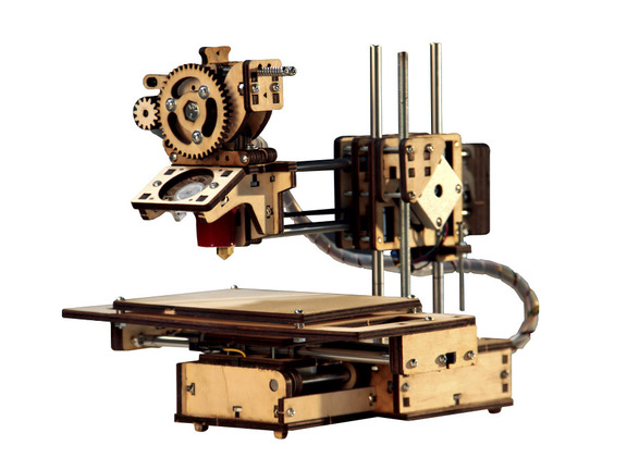
Dear Reader, after a short break, we continue to collect our wonderful 3D printer, or rather, we are preparing for the collection by absorbing the invaluable experience of the pioneers.
From the first part, we already know the peculiarities of overseas plywood cut on a laser machine, and we have an idea of the “sandwiches” made of it.
We talked about PVA, oil, gears and the Museum of Isaac, and how they need each other.
Next, we'll talk a little more about plywood and move on to the cogs.
')
I asked to the table, boiled. (WITH)
Any thoughts on additional grinding of plywood categorically discard in vain. Overseas plywood from birth has a very smooth surface, in any case, I did not get ready-made analogue for sale on this class. However, the wood itself has a very delicate and specific structure. It is enough to hold a smooth plywood even with a conventional microfiber cloth to brush away dust, for example, or to wipe how the surface is transformed and uplifted by millions of villi that can not be laid in any way. Polishing zero sandpaper does not help, rather the opposite. At the same time, neither smooth nor “fluffy” surfaces leave splinters on their hands, which categorically and irrevocably tears up the peace treaty with Russian tree saws.
Oh-oh-oh ... this is a separate topic.
When I began to twist the first two parts of the base of the printer, Musa Isaakovna, standing nearby, quiveringly froze. Turnover ... second ... third ... tension ... voila! The nut ideally got into the slot, the parts stood in the grooves of each other and the screw, ideally hitting the nut, firmly pressed it to the body to the full depth, slightly coming out from the other side. Musa Isaakovna, splashing her hands, bounced on her toes, “Bravo!” - and visibly built added to the bust.

It was the best bust of all time ... Next, he changed the size and shape, from the White Naliv to the Usani Spaniel and back, but was never the same as he appeared at that moment.
With each next detail, the design strengthened and at the same time, the unwillingness of parts to connect with each other became stronger. At first, this was expressed in enlarged gaps, which, for the prevention of deflection of plywood when tightening the screw, I recommend abundantly filling it with glue in the area of the screw itself.
Then frankly defective parts began to come across, such as, for example, a small plank on the right side of the base, under the axle.
In this case, nothing could be fixed, since the screw hole simply did not coincide with the slot for the nut, And the nut did not turn only on an honest word.
one

2
3
Regardless of what kind of power supply you use, standard from a laptop, or ATX in the case of installing a hot table upgrade, install the power adapter jack in the base of the printer.
one
2
ATH power goes directly through two pairs of cables and directly to the board, which is not very convenient and aesthetic. But if you have a different power supply with the necessary power with the appropriate connector, you can elegantly plug it into the socket.
At this moment, Muza Isaakovna looked languidly at the balzak age, evoking respect, but not evoking a reciprocal feeling.

In the far-distant land, it was decided once that high-tech carriers twist the parts together with one screw and without a nut.
And the blessing was their initiative, because on the nuts saved and the assembly time millions could be raised.
And everything would be fine if that thread were cut into details only in the last one, so that all the others would be mobile and would not cling to the thread, allowing them to squeeze themselves stronger. But either the creators forgot about the existence of a bolt with specially for such cases cut threads not under the bonnet, or intermediate parts had to be positioned without fail and again without additional nuts, in general our bolt was screwed tightly and into all the details and, of course, by no means they did not squeeze them between them anymore.
The correct bolt for sandwiches
Before you collect these sandwiches, stock up with a clamp, which pre-squeeze the workpiece. And then tighten the screws.
Please also note that the bearings touch the plywood not along the plane, but along the line, along the edge of the seats. It is recommended to pour plenty of faces of the PVA bearings, not inside! This will additionally fix the bearing (there are grooves on the bearing, into which glue will fall), will increase the contact area and protect the thin side of the plywood from curing under load and chipping during operation.
one

2
The installation of the hot table upgrade ( Heated Bed Upgrade ) turned out to be a really serious blow to the libido.
In strict accordance with the assembly instructions, it was proposed to fasten the heating element to the plywood base with 8-mm screws and nuts, provided that the plywood thickness was 6 mm and the heater thickness was 2 mm.
At that moment, Muza Isaakovna, leaning heavily on crutches, tried to leave the room, but under Zigmund Yakovlevich’s gaze, she returned to her seat and painfully stepped on the dignity of the author.
We will not give a monologue of Zigmund Yakovlevich, in which he explained the reasons that prompted overseas designers to come to such an unconventional solution.
Instead, we express our gratitude to Muse Isaakovna, who, creating excessive pressure on the author’s dignity, encouraged him to make a cardinal decision.
The solution is to press the nuts into the plywood, by means of proskubitsev with a pair of washers on each side to protect the plywood and some skill.
one
2
3

Muse Isaakovna rose.
Long live thanks to what we - no matter what! (WITH)
And about the bearings in general, only one thing - absolutely not to assemble them as indicated in the main instructions. To avoid misalignment, the bearings should first be put on the axles, then placed in the seats along with the axles and only in such a way tighten the sandwich. Otherwise, after installing the bearings separately, the installation of the axis will be difficult. Bearings will slightly change their landing position, breaking the gluing and plywood edges, and in some cases the end of the axle will knock small balls out of the bearing as they slide longitudinally inside a closed loop in the linear bearing housing.
Balls, if not lost, then you can insert back, removing the axis and strongly pushing them with a thin screwdriver into the plastic groove of the inner sleeve, but this thing is quite difficult and not the first time.
After assembling the entire printer, all the bearings and the screw axis Z with a nut are recommended to be additionally lubricated with a WD-shk, after removing dust and dirt from the axes. And set a simple program for the printer to drive all the axles back and forth several times and smear the grease.
The G-code sequence for a working volume of 130x110x85 mm, which is exactly the amount you have left after installing on Printrbot Jr Heated Bed Upgrade, can be like this:
More about the G-code for RepRap can be found here .
The assembly that has now been considered is the bearing block for the YZ axes and the power nut of the Z axis.
This site has its own three nuances.
The limit switch of the Y axis according to the instructions is attached to the cable tie (like the other two). On good, it should be replaced with two screws, with gadget. But if there are no suitable screws, do not forget to put all the switches on the glue and carefully spill the holes with the PVA tie. Without this, the switches will be movable no matter how you tighten the clamp.
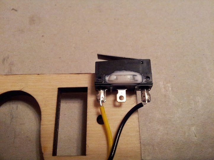
At the bottom of the assembly there is an original technical solution for installing a pin (also known as a long screw with two counter-nuts) for pressing the Z-axis limit switch installed inside the base of the printer. Such a kind of plywood plate, which according to the idea should be pushed through into special slots perpendicular to the main body of the unit. Of course the disc is much thicker than the slot. And even if you process and slightly expand the slots with a file (and you can only expand one first slot, the second file does not work out at the right angle if the assembly is complete ), the disc will still not fit. Only with pliers and only at the last moment breaking the plate in the thinnest point on the diameter of the large hole you can install it more or less correctly, but with a certain bias with respect to the horizon, since the pliers are not parallel sponges.
one
2
3
four
If all this happened that way, carefully coat the plate with glue from all sides, pour glue into all the cracks, especially where the plate has cracked, since it is no longer possible to pull the plate back after pressing. Fortunately, the plate practically does not experience power loads during operation, so the glue from the outside will help it well and the current multi-day operation confirms this.
All this could have been avoided if we carefully read the instructions at this stage of the assembly, where it would be written in black and white: “Since this part is thicker than the slits, reduce the thickness of the part on the skin. This will make fitting the part easier. ”
But since you could not assume that the slots on the laser machine can certainly be done already than the part that should be inserted into them - you did not read it. Therefore, do not feel sorry for the glue.
The curtain rises.
From the depth of the twilight scene, a naked old man slowly emerges into the light of the central circle. He moves extremely slowly and while he finally comes to light passes no less than ten minutes. The old man is absolutely naked, his hair and beard are disheveled and not fresh.
He stops in the middle of the stage and slowly circles the silent and silent audience with a sharp and sharp look. The hall is full.
Suddenly the old man starts screaming and jumping and jumping around the stage with incredible grimaces and grimaces of a child. Shock action lasts no more than a minute. Then the old man also suddenly stops wriggling and stands still at attention in a lighted circle. He turns his back to the public and as slowly as he came into darkness.
A curtain.
Pause, rotten tomatoes, dissatisfied cries.
Printer motors weigh about 250 grams each; I won’t say for sure, but four motors weigh a little more than a kilogram by eye.
Two of the four motors are in space in motion; these are the Y axis motor and the extruder motor.
All this economy, along with the hot end, steel axles and bearings is held on weight and moves along the Z axis with a single nut, which in turn is screwed onto a helical axis connected to the Z axis motor.
The nut has a fully standard size in its inch size and ...
And it does not correspond to the loads and the accuracy of movement, which are assigned to it.
To make it clear, any nut, including ours, moves along the thread with some minimum backlash (if it is in free movement and is not restricted in any way by freedoms). Backlash is both axial and longitudinal, along the axis of the screw. So if this gap is comparable to the thickness of the printed layer, and in our case the author works with a layer of 0.2 mm (we will talk about printing resolution, layers, thickness, quality and nozzles separately), then as soon as the nut comes across imperfections in the thread on the Z axis so immediately you will feel it on the quality of the layer. And the nut will definitely come across defects, since there are no perfect threads and the Z-axis travel is large enough, 85 mm in our case with PB Jr. Over time, the thread will be added to the nut and the number of defects will decrease, but all of them will not go away and will be especially noticeable at the beginning. Either stand in this place will peel off on the finished part at the slightest pressing, or you will see during the printing process how the nozzle is buried in the molten plastic of the previous layer.
Thus, I highly recommend replacing the standard flat nut with a long one. This will help “filter out” minor defects in the axis threads and minimize the effect of thread defects on print quality in principle.
If you are not destined to find a long nut with the required inch thread, which is what happened to the author, then go to the bust of Muza Isaakovna and use a regular nut.
Installing the nut at the beginning and from the assembly instructions is incomprehensible, in fact, quite primitive and in fact does not hold water. The nut enters with two angles from six into special slots on the bearing assembly, discussed above.
And that's all.
This seems incomprehensible in the beginning, and in fact, debriefing flights completely discredits Musa Isaakovna and causes Zygmund Yakovlevich’s Homeric laughter. But do not quarrel with them, they will still be useful to you, both.
By the way
As a graphic example of the simultaneous non-triviality and elementary nature of the problem, a live video of an unfortunate pioneer.
Understand. I grieve.
In conclusion, several illustrative photos of where and how exactly our notorious nut should stand:
1 Bottom view
2 front view
3 rear view
4 top view
And don't forget the glue.
My friends!
I could not, could not ... (C)
finish everything in the second part. But there is still gunpowder in the flasks and berries in the buttocks, which I will tell in the third part, and finally move on to the calibration.
Dear Reader, after a short break, we continue to collect our wonderful 3D printer, or rather, we are preparing for the collection by absorbing the invaluable experience of the pioneers.
From the first part, we already know the peculiarities of overseas plywood cut on a laser machine, and we have an idea of the “sandwiches” made of it.
We talked about PVA, oil, gears and the Museum of Isaac, and how they need each other.
Next, we'll talk a little more about plywood and move on to the cogs.
')
I asked to the table, boiled. (WITH)
Part 2 (continued)
Assembling and testing accelerating units of heavy carrier rockets
And a little more about plywood
Any thoughts on additional grinding of plywood categorically discard in vain. Overseas plywood from birth has a very smooth surface, in any case, I did not get ready-made analogue for sale on this class. However, the wood itself has a very delicate and specific structure. It is enough to hold a smooth plywood even with a conventional microfiber cloth to brush away dust, for example, or to wipe how the surface is transformed and uplifted by millions of villi that can not be laid in any way. Polishing zero sandpaper does not help, rather the opposite. At the same time, neither smooth nor “fluffy” surfaces leave splinters on their hands, which categorically and irrevocably tears up the peace treaty with Russian tree saws.
About cogs
Oh-oh-oh ... this is a separate topic.
When I began to twist the first two parts of the base of the printer, Musa Isaakovna, standing nearby, quiveringly froze. Turnover ... second ... third ... tension ... voila! The nut ideally got into the slot, the parts stood in the grooves of each other and the screw, ideally hitting the nut, firmly pressed it to the body to the full depth, slightly coming out from the other side. Musa Isaakovna, splashing her hands, bounced on her toes, “Bravo!” - and visibly built added to the bust.
It was the best bust of all time ... Next, he changed the size and shape, from the White Naliv to the Usani Spaniel and back, but was never the same as he appeared at that moment.
With each next detail, the design strengthened and at the same time, the unwillingness of parts to connect with each other became stronger. At first, this was expressed in enlarged gaps, which, for the prevention of deflection of plywood when tightening the screw, I recommend abundantly filling it with glue in the area of the screw itself.
Then frankly defective parts began to come across, such as, for example, a small plank on the right side of the base, under the axle.
In this case, nothing could be fixed, since the screw hole simply did not coincide with the slot for the nut, And the nut did not turn only on an honest word.
one
2
3
Remarochka
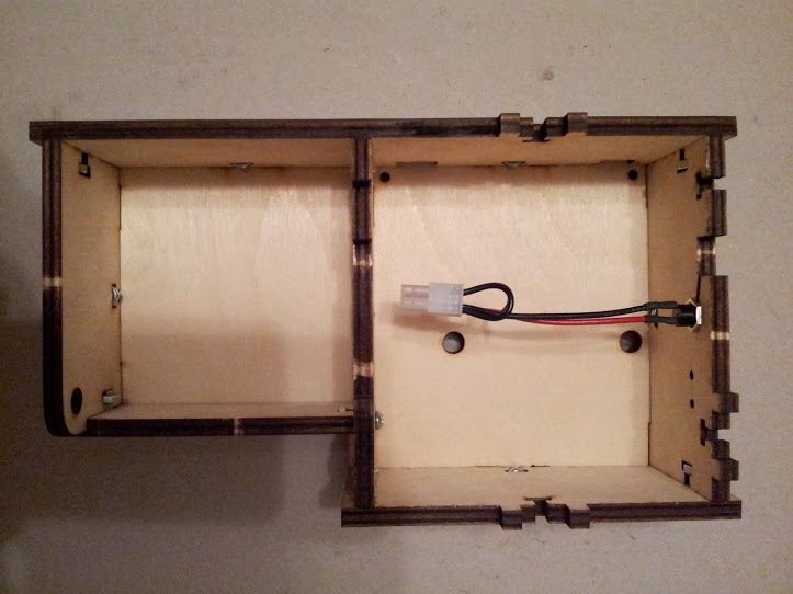
Regardless of what kind of power supply you use, standard from a laptop, or ATX in the case of installing a hot table upgrade, install the power adapter jack in the base of the printer.
one
2
ATH power goes directly through two pairs of cables and directly to the board, which is not very convenient and aesthetic. But if you have a different power supply with the necessary power with the appropriate connector, you can elegantly plug it into the socket.
Extravaganza was the first sandwich
At this moment, Muza Isaakovna looked languidly at the balzak age, evoking respect, but not evoking a reciprocal feeling.
In the far-distant land, it was decided once that high-tech carriers twist the parts together with one screw and without a nut.
And the blessing was their initiative, because on the nuts saved and the assembly time millions could be raised.
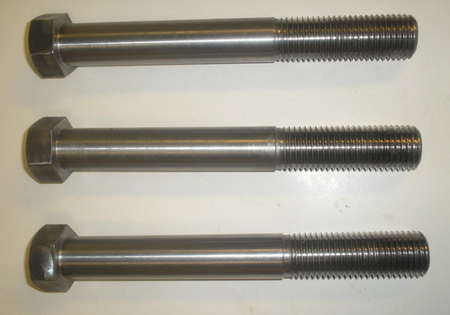
And everything would be fine if that thread were cut into details only in the last one, so that all the others would be mobile and would not cling to the thread, allowing them to squeeze themselves stronger. But either the creators forgot about the existence of a bolt with specially for such cases cut threads not under the bonnet, or intermediate parts had to be positioned without fail and again without additional nuts, in general our bolt was screwed tightly and into all the details and, of course, by no means they did not squeeze them between them anymore.
The correct bolt for sandwiches
Morality
Before you collect these sandwiches, stock up with a clamp, which pre-squeeze the workpiece. And then tighten the screws.
Please also note that the bearings touch the plywood not along the plane, but along the line, along the edge of the seats. It is recommended to pour plenty of faces of the PVA bearings, not inside! This will additionally fix the bearing (there are grooves on the bearing, into which glue will fall), will increase the contact area and protect the thin side of the plywood from curing under load and chipping during operation.
one
2
Prohibited reception (C)
The installation of the hot table upgrade ( Heated Bed Upgrade ) turned out to be a really serious blow to the libido.
In strict accordance with the assembly instructions, it was proposed to fasten the heating element to the plywood base with 8-mm screws and nuts, provided that the plywood thickness was 6 mm and the heater thickness was 2 mm.
At that moment, Muza Isaakovna, leaning heavily on crutches, tried to leave the room, but under Zigmund Yakovlevich’s gaze, she returned to her seat and painfully stepped on the dignity of the author.
We will not give a monologue of Zigmund Yakovlevich, in which he explained the reasons that prompted overseas designers to come to such an unconventional solution.
Instead, we express our gratitude to Muse Isaakovna, who, creating excessive pressure on the author’s dignity, encouraged him to make a cardinal decision.
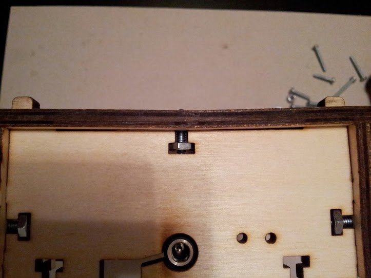
The solution is to press the nuts into the plywood, by means of proskubitsev with a pair of washers on each side to protect the plywood and some skill.
one
2
3
Muse Isaakovna rose.
Long live thanks to what we - no matter what! (WITH)
Pro bearings
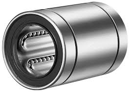
And about the bearings in general, only one thing - absolutely not to assemble them as indicated in the main instructions. To avoid misalignment, the bearings should first be put on the axles, then placed in the seats along with the axles and only in such a way tighten the sandwich. Otherwise, after installing the bearings separately, the installation of the axis will be difficult. Bearings will slightly change their landing position, breaking the gluing and plywood edges, and in some cases the end of the axle will knock small balls out of the bearing as they slide longitudinally inside a closed loop in the linear bearing housing.
Balls, if not lost, then you can insert back, removing the axis and strongly pushing them with a thin screwdriver into the plastic groove of the inner sleeve, but this thing is quite difficult and not the first time.
After assembling the entire printer, all the bearings and the screw axis Z with a nut are recommended to be additionally lubricated with a WD-shk, after removing dust and dirt from the axes. And set a simple program for the printer to drive all the axles back and forth several times and smear the grease.
The G-code sequence for a working volume of 130x110x85 mm, which is exactly the amount you have left after installing on Printrbot Jr Heated Bed Upgrade, can be like this:
G28 G21 G91 G1 X5 Y5 F4000 G1 Z5 F2000 G1 X125 Y105 F4000 G1 Z80 F2000 G1 X-125 Y-105 F4000 G1 Z-80 F2000 G1 X125 Y105 F4000 G1 X-125 Y-105 F4000 G1 X125 Y105 F4000 G1 X-125 Y-105 F4000 G28 More about the G-code for RepRap can be found here .
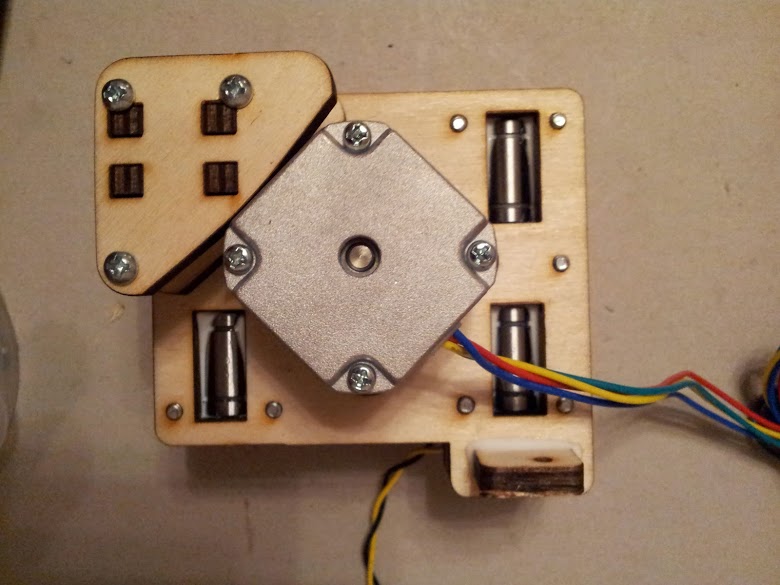
The assembly that has now been considered is the bearing block for the YZ axes and the power nut of the Z axis.
This site has its own three nuances.
First call
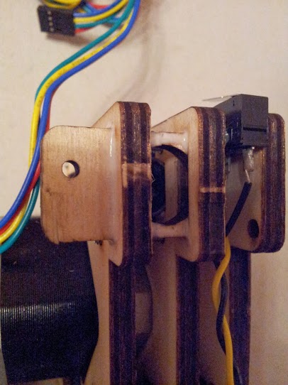
The limit switch of the Y axis according to the instructions is attached to the cable tie (like the other two). On good, it should be replaced with two screws, with gadget. But if there are no suitable screws, do not forget to put all the switches on the glue and carefully spill the holes with the PVA tie. Without this, the switches will be movable no matter how you tighten the clamp.
Second call
At the bottom of the assembly there is an original technical solution for installing a pin (also known as a long screw with two counter-nuts) for pressing the Z-axis limit switch installed inside the base of the printer. Such a kind of plywood plate, which according to the idea should be pushed through into special slots perpendicular to the main body of the unit. Of course the disc is much thicker than the slot. And even if you process and slightly expand the slots with a file (and you can only expand one first slot, the second file does not work out at the right angle if the assembly is complete ), the disc will still not fit. Only with pliers and only at the last moment breaking the plate in the thinnest point on the diameter of the large hole you can install it more or less correctly, but with a certain bias with respect to the horizon, since the pliers are not parallel sponges.
one
2
3
four
If all this happened that way, carefully coat the plate with glue from all sides, pour glue into all the cracks, especially where the plate has cracked, since it is no longer possible to pull the plate back after pressing. Fortunately, the plate practically does not experience power loads during operation, so the glue from the outside will help it well and the current multi-day operation confirms this.
By the way
All this could have been avoided if we carefully read the instructions at this stage of the assembly, where it would be written in black and white: “Since this part is thicker than the slits, reduce the thickness of the part on the skin. This will make fitting the part easier. ”
But since you could not assume that the slots on the laser machine can certainly be done already than the part that should be inserted into them - you did not read it. Therefore, do not feel sorry for the glue.
Third bell
The curtain rises.
From the depth of the twilight scene, a naked old man slowly emerges into the light of the central circle. He moves extremely slowly and while he finally comes to light passes no less than ten minutes. The old man is absolutely naked, his hair and beard are disheveled and not fresh.
He stops in the middle of the stage and slowly circles the silent and silent audience with a sharp and sharp look. The hall is full.
Suddenly the old man starts screaming and jumping and jumping around the stage with incredible grimaces and grimaces of a child. Shock action lasts no more than a minute. Then the old man also suddenly stops wriggling and stands still at attention in a lighted circle. He turns his back to the public and as slowly as he came into darkness.
A curtain.
Pause, rotten tomatoes, dissatisfied cries.
Printer motors weigh about 250 grams each; I won’t say for sure, but four motors weigh a little more than a kilogram by eye.
Two of the four motors are in space in motion; these are the Y axis motor and the extruder motor.
All this economy, along with the hot end, steel axles and bearings is held on weight and moves along the Z axis with a single nut, which in turn is screwed onto a helical axis connected to the Z axis motor.
The nut has a fully standard size in its inch size and ...
And it does not correspond to the loads and the accuracy of movement, which are assigned to it.
To make it clear, any nut, including ours, moves along the thread with some minimum backlash (if it is in free movement and is not restricted in any way by freedoms). Backlash is both axial and longitudinal, along the axis of the screw. So if this gap is comparable to the thickness of the printed layer, and in our case the author works with a layer of 0.2 mm (we will talk about printing resolution, layers, thickness, quality and nozzles separately), then as soon as the nut comes across imperfections in the thread on the Z axis so immediately you will feel it on the quality of the layer. And the nut will definitely come across defects, since there are no perfect threads and the Z-axis travel is large enough, 85 mm in our case with PB Jr. Over time, the thread will be added to the nut and the number of defects will decrease, but all of them will not go away and will be especially noticeable at the beginning. Either stand in this place will peel off on the finished part at the slightest pressing, or you will see during the printing process how the nozzle is buried in the molten plastic of the previous layer.
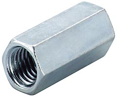
Thus, I highly recommend replacing the standard flat nut with a long one. This will help “filter out” minor defects in the axis threads and minimize the effect of thread defects on print quality in principle.
If you are not destined to find a long nut with the required inch thread, which is what happened to the author, then go to the bust of Muza Isaakovna and use a regular nut.
Nuance
Installing the nut at the beginning and from the assembly instructions is incomprehensible, in fact, quite primitive and in fact does not hold water. The nut enters with two angles from six into special slots on the bearing assembly, discussed above.
And that's all.
This seems incomprehensible in the beginning, and in fact, debriefing flights completely discredits Musa Isaakovna and causes Zygmund Yakovlevich’s Homeric laughter. But do not quarrel with them, they will still be useful to you, both.
By the way
As a graphic example of the simultaneous non-triviality and elementary nature of the problem, a live video of an unfortunate pioneer.
Understand. I grieve.
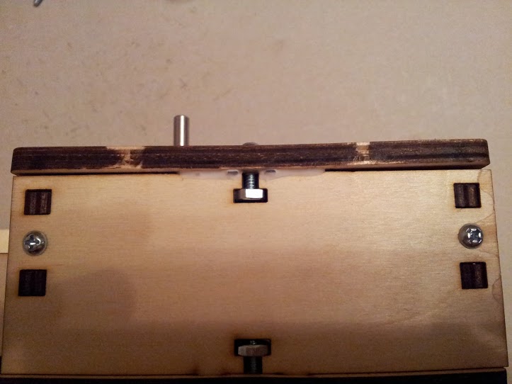
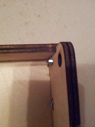
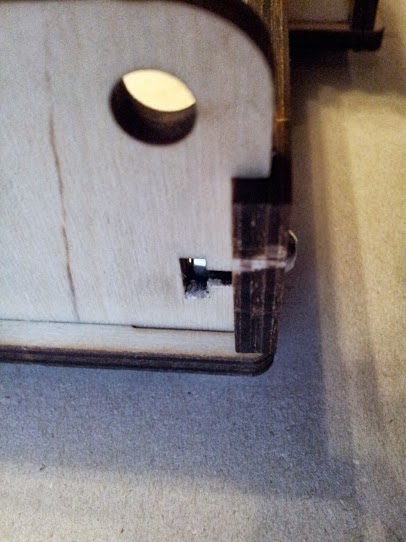
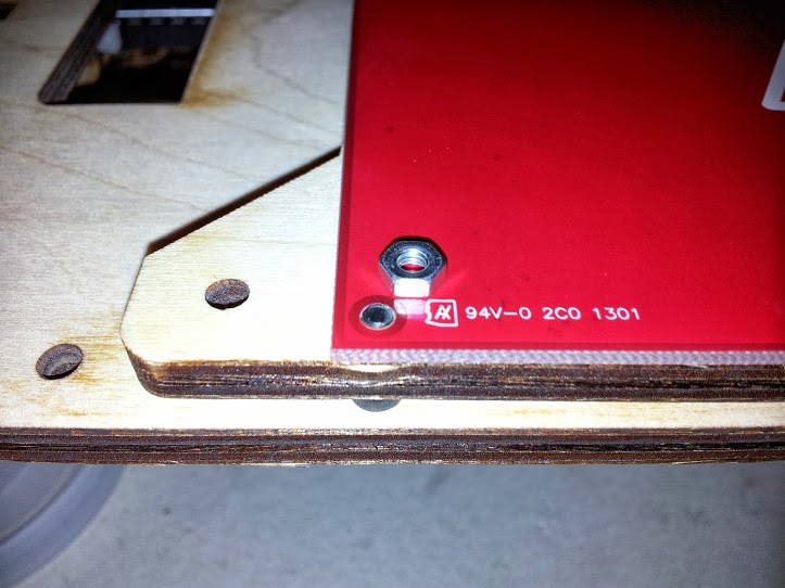
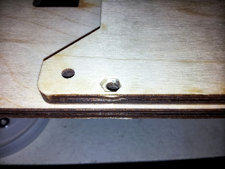
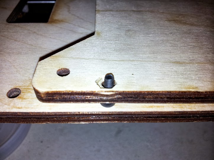
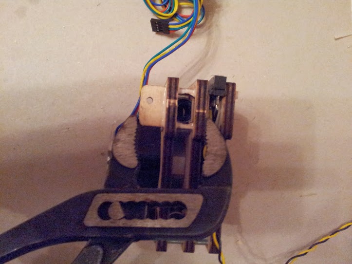
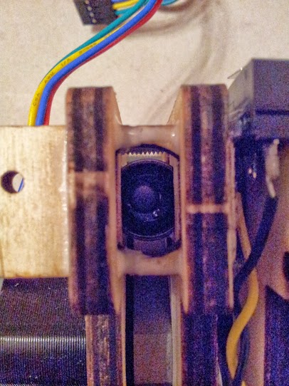
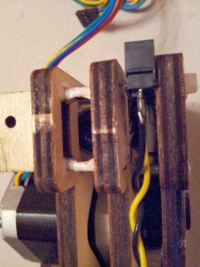
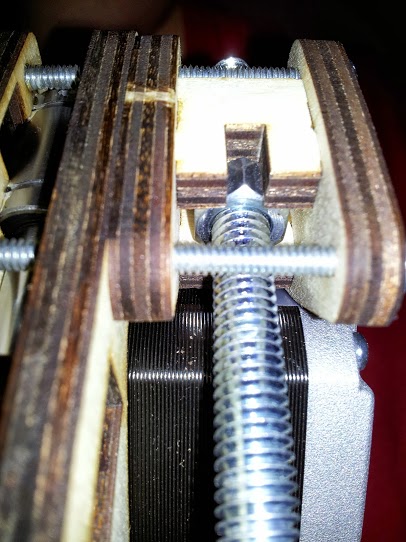
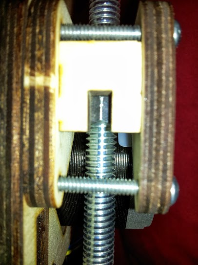
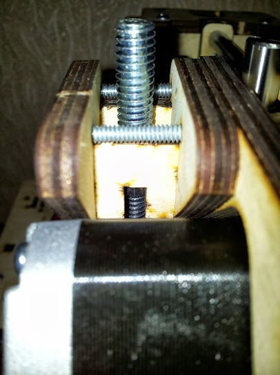
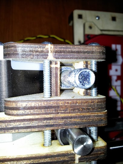
In conclusion, several illustrative photos of where and how exactly our notorious nut should stand:
1 Bottom view
2 front view
3 rear view
4 top view
And don't forget the glue.
Break
My friends!
I could not, could not ... (C)
finish everything in the second part. But there is still gunpowder in the flasks and berries in the buttocks, which I will tell in the third part, and finally move on to the calibration.
Source: https://habr.com/ru/post/197816/
All Articles