Industrial programming, or a couple of words about the process control system
There is such a profession - to automate production. The abbreviation of the automated process control system means "automated process control system" is a system consisting of personnel and a set of equipment with software used to automate the functions of this very person to manage industrial facilities: power plants, boiler rooms, pump houses, water treatment plants, food, chemical, metallurgical plants, oil and gas facilities, etc. etc.
In fact, every person who does not live in the forest and enjoys the benefits of civilization uses the results of the labor of the enterprises in which the automated process control systems are functioning.
')
Sometimes on this topic, skip articles and Habré. Usually they are not very popular, but I still want to write a few review articles about the process control system in the hope of telling the habravchan something interesting (and maybe even useful to someone) and attract more of my colleagues to the habr.
First a couple of words about yourself. I am just beginning my career in automation, almost two years of work experience. During this time, I visited several gas fields, now I work on an oil field.
Since the area is vast, in spite of everything developing, sometimes contradictory and controversial, I will try to generalize not to the detriment of authenticity, but I can’t avoid a bias in my area - the equipment, software and sphere that I personally encountered.
So, the software and hardware complex of the ACS TP is divided into three levels: upper (computers), middle (controllers), lower (field equipment, sensors, actuators). I will not tell about the lower level - this is too far from the subject of Habr, and the article will turn out too big.
Upper level
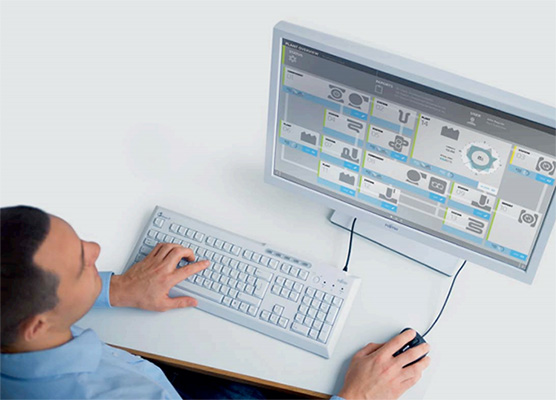
The upper level is the servers and user PCs (we have them called AWS - automated workplace). The state of the technological process is displayed here, and from here, if necessary, the operator sends commands to change its parameters. To simplify development, a large number of SCADA-systems have been created (from the English word. Supervisory control and data acquisition - dispatch control and data collection). This is in some way an advanced analogue of the IDE, in which the compiled "program" is executed.
SCADA systems
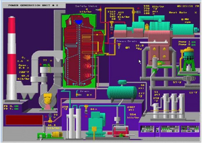
In general, if we reject academicism, then at the enterprise for everyone except the asusnika scud looks like this:

And if you’re not lucky, then like this:
Scuds can be implicitly divided into server and client parts. The survey of field devices and data collection is done by the server (usually through the PLC ), from the server the clients take this data to their monitor. The concepts of "server" and "client" parts are conditional. In fact, the separation is made under licenses for components Scuda, and each manufacturer has its own licensing policy. Up to the division into: the number of signals processed from the field, the protocol driver, the number of workstations, the ability to create a web interface, a mobile interface, and indeed whole pieces of functionality can be separate deneki. More often, it is easier to contact the supplier, providing the initial data on the project to help with the selection of licenses.
Two modes of operation are implied: development mode and execution mode (runtime). These modes are not necessarily mutually exclusive: you can edit the project on one workstation, engineering, upload it, it will be updated to the user. This is very important - to change the project without downtime and outages, because the process can not be interrupted, and operators should always be able to control it. In the CUDA, graphical interfaces are created, data sources from field devices are configured, it is responsible for the interaction of the user (operator, dispatcher, technologist) with what is happening in production, as well as for archiving all the necessary data in the database.
Archiving is one of the essential functions; it is very important to be able to “go back in time” for debriefing in case of something unexpected or for global analysis during slow, long processes. For example, geologists recently asked me to unload a plate with data on the pressure of oil on wells over the past year.
Periodically scada adds all collected data to the database. They can then be viewed in the form of graphs (we call them trends), and if necessary, if specified in the TOR on the automated process control system, the unloading is carried out in the form of reports to Excel or something else. Archiving is done differently: in MS SQL; MS Access; in the same MS SQL, but in its cunning algorithm with additional archiving; and someone else in their own binary database.
A special point in the drive is informing the operator: current messages and emergency. They are also archived. In general, messages are divided into current and important (emergency). The current ones are hidden away, but the alarm log is always displayed on the operator’s screen. Sound messages are tied to text alarm messages so that someone does not overstep the emergency :-)
SCADA Market
The most common, in my opinion, are considered to be the production of Invensys Wonderware, Iconics, Siemens, Indusoft, AdAstra, Emerson, Rockwell Automation.
I personally worked with Windows drivers: Invensys Wonderware InTouch and the more powerful System Platform, with Iconics Genesis32 - and with (for now?) The little-known B & R APROL under SLES (formally, this isn’t quite the case, and the controllers are also programmed from under the aprola) ).
For search queries, for example, SCADA , HMI, you can see examples of interfaces and mnemonic diagrams.
Appearance and usability by priority, alas, are in last place. Moreover, this concerns not only runtime, but also development. For development in each scud there are at least default libraries of symbols - from buttons and other controls to graphic images of pumps, pipes, valves, and containers. This is where smart developers of SCADA packages (not to be confused with us, asushniki - project developers in these packages) could achieve a fundamental advantage over competitors by making thoughtful libraries, of which even the most distant engineer and usability could have done would humane interfaces and mnemonic schemes. Unfortunately, now this area is on the path of extensive development, which has developed IT until recently - building up the functionality, adding buns, more, higher, stronger, harder,
Average level
Middle level - PLC, programmable logic controllers. Everything is quite simple here, most often physically the PLC consists of separate modules. Each PLC has its own development environment for programming, sometimes it is combined with the SCADA environment.
PLC composition
Modules are as follows:
- Power Supply;
- processor;
- discrete inputs;
- discrete outputs;
- analog inputs;
- analog outputs;
- temperature inputs;
- interface / communication
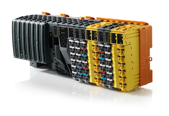
B & R X20 Series Controller
Why do I need a power supply - is understandable. The power supply unit is made as a separate module, not as a device, in order to guarantee compatibility with this PLC line. Most often, the input voltage at the PSU is 220 V AC, the output voltage is 24 V DC.
The processor module is the PLC head. Inside it has, of course, the CPU, RAM and ROM, the service port for the firmware and, possibly, the communication port (ethernet, RS232 / 422/485, Profibus, etc). Sometimes the communication port is also used as a service port. Sometimes there is a switch on the module (Allen Bradley is even cooler - there is a natural key with a keyhole) for translating the PLC into various modes of operation. There is no separate on / off button, at best - that switch, otherwise, if there is power, the PLC starts and shuts down and restarts “barbarously” by turning off the power.
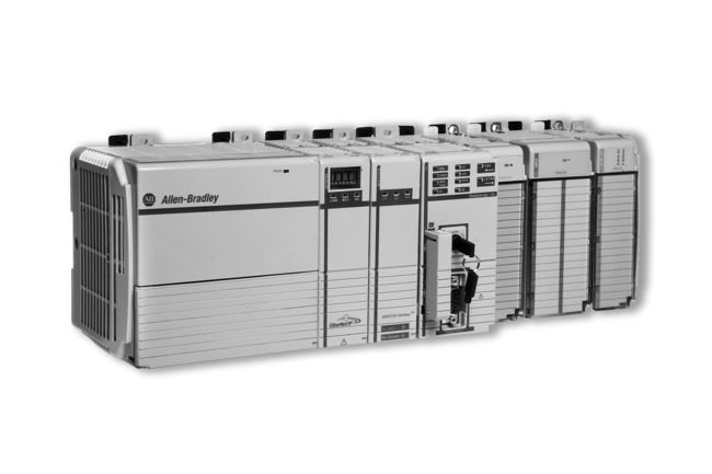
Allen Bradley Controller CompactLogix Series
Discrete and analog modules process the corresponding signals. Input modules receive these signals from the field, output - form them.
A discrete signal is usually a 24 volt circuit voltage. There are 24 - this is "1", no - "0". There are modules for 220V, there are modules with checking the integrity of the circuit. Discrete signals coming from the field can inform, for example, the status of the pump on / off. Control discrete signals can start or stop this pump. Optimization is not justified here, so there will be a separate circuit for the launch, a separate one for the shutdown.
I / O modules of the same type can be combined: for example, one module with 16 discrete inputs and 16 discrete outputs.
Analog input signals - these are readings from the sensors. Here, the most frequently used current loop is 4-20 mA, according to which the limits of measurement of the sensor are set. It starts from 4 mA to diagnose an open circuit (if less than 4 mA, it means that somewhere there is something wrong with the wiring).
Consider the example of the level of liquid in the tank. There is a level gauge, it measures the level from 0 to 2 meters. Then: the level of 0 meters is 4 mA, the level of 2 meters is 20 mA. Intermediate values are calibrated according to the situation, not always 1 meter corresponds to 4+ (20-4) / 2 = 12 mA, there may be a small error, the level of 1 meter may be some 12.7553 mA.
Analog output is the same, only for control. I have not met to be used, because There are always tips. In measurement, this is the permissible error, in control it is not. Yes, and it is inconvenient. Instead, digital data transfer using various protocols via communication modules is used.
Temperature modules measure the resistance in the circuit or thermo-emf. If resistance thermometers are connected to them - when the metal is heated, its resistance, according to the laws of physics, increases, respectively, the temperature is determined. If a thermocouple is connected (two welded conductors of different metals, a potential difference between the other ends occurs when the joint is heated), the voltage is measured.
Interface (or communication) modules provide us with ports for RJ45, DB9, DB15, just terminals and what else God will put on the manufacturer. In addition to implementing the interface directly (the physical connector for the connector, the physical layer of the OSI model), they also implement the exchange protocol through this connector.
Protocols and interfaces
Protocols invented and used a bunch: ModBus (RTU, TCP, ASCII), Profibus, Profinet, CAN, HART, DF1, DH485, etc. Some particularly tricky manufacturers implement their protocols on top of the generally accepted ones.
I know quite closely the RS232 / 485 interfaces and Modbus protocols. RS232 is a familiar COM port with all three main lines: Tx (transmit, transmit), Rx (recieve, receive) and GND (ground, ground). RS485 is an asynchronous half duplex serial interface over 2 wires (combined Tx / Rx + and Tx / Rx-) or 4 wires (separate Tx +, Tx-, Rx +, Rx-) with a potential difference on each pair from 2 to 10 volts.
A modbas is in general a simple thing, with checking the integrity of the package according to the check amount, confirming the delivery and the correctness of the request - or the answer why the request is incorrect. There are two types of devices in the modbas network: master - initiates the exchange; slave - performs master requests. A packet from the master diverges to all the slaves that compare the destination address with its own, if it converges, then the next two bytes are viewed - this is the command to work with memory registers - read / write (except for a few rarely used service commands), then the address bytes and the data itself at the end of cheksumma. Enough detail and clearly painted on Wikipedia .
Software stuffing
The first thing to say, the program in the PLC is executed cyclically with a certain frequency. The possibilities depend on the controller, usually it is somewhere around 20, 50, 250 ms, 1, 2, 3, 4, 5 s. Naturally, this does not guarantee the execution of the code for such a period of time, it is impossible to push large programs into a 20 ms cycle, by the beginning of the next cycle the previous one should be completed.
The second is programming languages. In theory, PLCs are programmed in languages defined by IEC 61131:
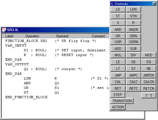
- IL (Instruction List) is a low-level assembly-like language.
- LD (Ladder Diagram) - a graphical language, is a software implementation of electrical circuits based on electromagnetic relays. Invented in shaggy years for those asusnikov, which are more electrics than programmers.
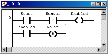
IL and LD are easily converted into each other, it seems, by all programming environments. They are not very readable, and therefore inconvenient for development, but in situations where the controller has little internal memory, you have to write them. - ST (Structured Text) is a text-like language. In my opinion, of all five, the most convenient.

- FBD (Function Block Diagram) is a kind of graphic language, “block-like”. The program is composed of functional blocks, which are subroutines written in any of the languages of the IEC 61131 standard. Each PB has inputs and outputs, which are connected to the inputs and outputs of other PBs. Someone may be more convenient to do so than to write everything on the same ST.

- SFC (Sequential Function Chart) is a graphical high-level language. Created on the basis of the mathematical apparatus of Petri nets. Describes the sequence of states and conditions of transitions. I have never met and never heard of being used somewhere.

This is "in theory." But, for example, Siemens adheres to its name of languages, while B & R has the opportunity to write in ANSI C.
The most used controllers, unconditionally, are from Siemens and Allen Bradley (the latter, by the way, belongs to Rockwell Automation with its line of RSAD SCADA packages). Behind them are Schneider Electric; ARIES; General Electric; AutomationDirect; ICP DAS; Advantech; Mitsubishi Electric; B & R.
Conclusion
The post does not pretend to a complete reference description of everything - very much different equipment, software and approaches to them as a whole. The most formally unmistakable story about the process control system would be the enumeration of the relevant Federal Law, GOST, technical standards and regulations. All possible discrepancies with these documents are considered to be misprints ;-) We are happy to accept comments, amendments and, if interested, suggestions for the following articles.
Source: https://habr.com/ru/post/197276/
All Articles