Work with TFT display on ARDUINO DUE
The second part is here: http://habrahabr.ru/post/196864/
This article opens a short series of articles on working with multi-color TFT displays on the Arduino DUE. In this and the following articles, the main features of TFT displays will be discussed, libraries will be described, examples of typical tasks arising from working with such displays will be considered.
Currently, there are many different TFT displays on the Arduino component market. From the user's point of view, they differ from each other mainly in size, resolution, connection methods and additional functionality. Most of these displays are equipped with a touch screen, which makes the control of the system more convenient and allows you to get rid of traditional buttons, joysticks, encoders and other mechanical devices.
Working with a graphic display with a resolution of the order of 320x240 and higher assumes the presence of a solid amount of memory and a rather high speed of the microcontroller itself. In addition, the connection often requires a large number of pins, so the Arduino DUE controller was chosen as the base.
The following equipment was used as an “experimental setup” when writing this article:
Pay attention, Schild is designed for Arduino DUE. To use the display with the Arduino MEGA, another plate version is needed, equipped with a 5v – 3.3v level converter.
All materials relating to pinout display and CTE plate can be downloaded on the manufacturer's website:
Display: http://coldtears.lin3.siteonlinetest.com/files/3.2b.zip
Schild: http://coldtears.lin3.siteonlinetest.com/files/CTE_DUE_shield.zip
To work with TFT displays, the UTFT library set is used. The most recent versions of these libraries can be found on the developer’s website: http://www.henningkarlsen.com/electronics/
After connecting the display, the following pins of the controller remain free: D0, D1, D8, D11-D13, D14-D24, D29-D31, D41-D43, A0-A11, DAC0, DAC1, SCL1, SDA1, which can be used at your discretion.
The UTFT library is designed to work with TFT displays of various types, connected both via a parallel (8bit or 16bit) and serial interface. It was originally developed to support displays made by ITead Studio and NKG Electronics, but then it was supported by several other manufacturers. The original library can be downloaded here: http://www.henningkarlsen.com/electronics/library.php?id=51
The library comes with pretty good documentation in English. This article is based mainly on developer documentation with the addition of a certain amount of practical experience and additional information that was obtained in the course of work.
')
A list of displays supported by the library and their main features are provided in the accompanying document “UTFT Supported display modules & controllers”, which is supplied with the library.
This library is basic and contains only the main display functionality. There are several additions to it that implement additional functions, such as control using the touch screen (U_Touch), working with on-screen buttons (UTFT_Buttons), an extended set of functions for drawing graphic primitives (UTFT_Geometry), using built-in fonts and icons in some displays (UTFT_CTE), etc.
The base library allows you to work with loadable fonts. Fonts are stored as data arrays, which are placed in separate files and connected to the program text.
The library can be used both with controllers based on AVR platform (Arduino MEGA), and with controllers on ARM platform (Arduino DUE). Before you start using the library with an Arduino DUE controller, you need to go to the folder where the library is installed: _ARDUINO_FOLDER_ / libraries / UTFT, find the folder / hardware / arm and the file HW_ARM_defines in it. In this file you need to uncomment the line:
The UTFT library also has a useful "trick" that allows you to disable the initialization codes of those display models that are not currently in use. This saves some amount of memory (for example, my compiled program size has decreased by almost 12 Kb). To do this, open the memorysaver.h file in the editor located in the root folder of the library and uncomment the lines with the names of those controllers that you do not plan to use in your project. At the same time, only one controller should be commented out - the one you use. Our display, as mentioned above, is equipped with an ILI9481 controller. Therefore, the line:
we leave it commented out, and in the remaining lines we delete all the characters // at the beginning of the lines. Now you can work.
The use of a library in a project begins with its loading and initialization. Initialization parameters depend on the type of display used. We load the UTFT base library and create an object - a display named myGLCD. Parameters - display model identifier and pin numbers to which RS, WR, CS, RST and ALE lines are connected. These parameters should be found out from the display manufacturer or selected by the list of supported displays that comes with the library.
In our version, a 3.2 ”display with a resolution of 480x320 and an ILI9481 controller manufactured by Coldtears electronics is referred to as the CTE32HR. In this case, according to the Schild scheme, control lines are connected to pins 25-28.
Next, you need to connect external fonts (we will not use the built-in fonts of the display yet - this is a topic for another conversation). The library comes with three basic fonts. Here is the ad string for these fonts:
So, we connected and initialized the library, attached the fonts, now we need to initialize our display in the void setup () procedure:
The InitLCD () command allows you to set the vertical or horizontal orientation of the display. By default (if the command is invoked without a parameter) the horizontal orientation is set. The clrScr () command; just clears the display. Note that the library does not have the concept of the background color of the entire display. After cleaning, the display always turns black.
Finally, before we move on to a detailed review of the library commands, finish our simplest example — choose the BigFont font and print the traditional “Hello, world!” In the center of the top line of the display:
When working with the library, you need to install it in the folder with the Arduino libraries and connect using the directive:
The description of the teams is taken mainly from the English manual supplied with the library, and is significantly complemented by practical observations and examples. So…
UTFT - creates a base display class with the specified name, specifies the model identifier and the connection method as parameters.
Two options are possible: for models with a parallel interface, the command is:
For models with a serial interface, the command is:
The string with this command is placed in the definition area and must precede any other library commands. The specified display name should be used as a prefix to all subsequent library commands.
InitLCD - initializes the display and sets the horizontal or vertical orientation. The orientation identifier is specified as a parameter.
Being set without parameters, the command sets the horizontal orientation. If you specify the PORTRAIT parameter or 0, the vertical orientation will be selected, if you specify LANDSCAPE or 1 is horizontal.
In the horizontal orientation, the connectors of the controller are located on the left, with the vertical - at the bottom. Other options are not provided. Setting a parameter other than 0 and 1 as a parameter results in a distorted display of information.
This command is usually used in the void setup () section, but it can also be used in the main program loop, as, for example, here:
In principle, by attaching a position sensor to the display, it would be possible to arrange a screen flip as in a tablet;)) however, during initialization the display flashes white for a short time, which spoils the impression. ;)
This command sets the background color to black, the text color to white, resets the font name used to “none”, and the result of the work of all print commands becomes unpredictable until the font is explicitly set (see the setFont command). After initialization, it is recommended to clear the display (see the clrScr command), and the screen will be filled with black.
clrScr - clears the display, erasing all information displayed on the display and filling the display with black color. It has no parameters.
When cleaning the display, the specified background color (see the setBackColor command) is not reset and remains the same, but the display is still filled with black. In order to clear a display with a different background color, use the fillScr command. The clrScr command is illustrated by the following example:
After the controller is reset, the display is initialized, then after 1 second cleaning (the display turns black) and after another second, the characters are displayed, and we see that the background color set before cleaning has not changed.
Before considering the following several commands, it is necessary to consider the specifics of specifying colors in library commands.
Color coding system
The colors in the library are defined in several ways. The internal format of the color data is RGB565. In this format, color is encoded with a 16-bit value, in which the level of red and blue is encoded by five bits, and green by six. Most of the library commands working with color take values that are given as three numbers separated by a comma. Each of these numbers is responsible for the level of the corresponding color (R, G, B). Valid values for each number are from 0 to 255.
Thus, the colors are specified by the user in the RGB888 format, and RGB565 is used inside the library. Format conversion is performed within the library using the following formula:
where color is the color value in RGB565 format, and r, g, and b are user-defined color values. It is in this format that values and all functions for determining the current color are returned.
When specifying colors, it is necessary to take into account that not all combinations of the specified values of r, g, and b will produce different colors. Therefore, for example, the red level values of 255 and 253 give the same red level. The program below displays the maximum and minimum values of r, g, and b valid for the color specified in the program in the color settings commands. To perform the calculation, substitute in the parameters of the myGLCD.setBackColor command decimal values of r, g and b for the selected color, compile and run the program. The display shows the color code in the RGB565 system, returned by the function myGLCD.getBackColor, as well as the minimum and maximum values of r, g, and b, which allow to obtain this color.
Some standard colors can be set using identifiers:
VGA_BLACK - black,
VGA_SILVER - silver
VGA_GRAY - gray
VGA_WHITE - white
VGA_MAROON - red-brown
VGA_RED - red
VGA_PURPLE - Magenta
VGA_FUCHSIA - Fuchsia
VGA_GREEN - green
VGA_LIME - Lime
VGA_NAVY - dark blue
VGA_BLUE - blue
VGA_TEAL - blue-green
VGA_AQUA - sea wave
If you want to find out the RGB codes for these colors - substitute the color identifier instead of three numbers into the myGLCD.setBackColor command in the above program, after compiling and running, the display will show the necessary codes.
So, we will continue the consideration of the library commands:
fillScr - clears the display, erasing all the information displayed on the display and filling it with the specified background color as a parameter.
The background color is defined by three numbers or a color identifier, for example, like this:
This command, like clrScr, does not change the specified background color for print commands, therefore, when printing on a display filled with the specified color, the background color must also be specified (see the setBackColor command).
setColor - sets the ink color for all commands for printing and drawing graphic primitives. The parameter indicates the desired color.
Colors are set the same way as for the fillScr command — either numbers or standard color identifiers. Example:
setBackColor - sets the background color for print commands. The parameter indicates the desired color.
Colors are set in the usual way - by numbers or identifiers (see the fillScr command), however, there is another identifier for this command - VGA_TRANSPARENT, which allows printing characters on a “transparent” background.
If you need to print on a display filled with any color other than black, you must set the exact same background color with the setBackColor command, or use the setBackColor (VGA_TRANSPARENT) command.
getColor - returns the current ink color value. It has no parameters.
getBackColor - returns the current value of the background color. It has no parameters.
These two functions return a word value corresponding to the currently specified color in RGB565 format. This value can be passed as a parameter in the setColor, SetBackColor and fillScr commands like this:
This command gives the same color as setColor (120,232.80) or setColor (125,233,84), as can be seen with the RGB565 color decoding program discussed above.
getDisplayXSize - returns the width of the display in pixels at the selected orientation. It has no parameters.
getDisplayYSize - returns the value of the display height in pixels at the selected orientation. It has no parameters.
These two functions can be illustrated by the following example:
When the program starts (vertical orientation is set), the display width will be equal to 320 pixels, and its height will be 480, after 2 seconds the orientation will change to horizontal and will become equal to 480 pixels, and will be 320 in height.
Before considering the print commands and working with fonts, it is necessary to elaborate on the methods of using fonts in the UTFT library.
External fonts for print commands.
External fonts are stored in separate files with the extension .c and represent arrays of data containing information about font parameters and encoded graphic images of characters.
The font is connected with the string "extern uint8_t _NAME_SHIFT_;". The extern qualifier indicates that the array with the font data is in another file, and the font name is taken from the font file. Please note that this is not the name of the file, but the name of the font itself (they may differ). Fonts used must be declared in your program using the extern specifier. For example:
The library comes with three main fonts:
Font SevenSegNumFont simulates a 7-segment digital indicator.
Additional fonts can be found here:
http://www.henningkarlsen.com/electronics/r_fonts.php
And here is an online service that allows you to create your own fonts from specially prepared graphic files:
http://www.henningkarlsen.com/electronics/t_make_font_file.php
The fonts included in the library bundle are stored in the DefaultFonts.c file in the root folder of the library. Additional fonts (drawn by yourself or downloaded from the above link) are recommended to be placed in the folder of your project, otherwise the compiler may not find them.
Font files are definitions of arrays containing service information and an encoded graphic image of a font. In addition to the title, the comments inside the font file also contain information on the size of the character in pixels (this information will be useful when setting the text display coordinates), the amount of memory occupied by the font data array and the number of characters specified in this font. There are "full" fonts of 95 characters, "digital" (10 characters) and "subsets" (a different number of characters).
The first 4 bytes of the array contain service information:
Byte 0 - horizontal font size in pixels
Byte 1 - vertical font size in pixels
Byte 2 is the code of the first character of the font (for “full” fonts, this is 0x20, that is, the space code, for “digital” - 0x30 - the character code “zero”).
Byte 3 - the number of characters of the font (for "full" fonts 0x5F, for "digital" - 0x0A).
More information about the subtleties of the format and creating custom fonts can be found here: http://www.henningkarlsen.com/electronics/h_utft_fonts_101.php
If you plan to work with large figures stylized as a 7-segment indicator, we recommend immediately replacing the SevenSegNumFont font with the alternative SevenSegNumFontPlus font, which can be downloaded here:
http://www.henningkarlsen.com/electronics/dlfont.php?id=21&t=c
it is distinguished by the presence of a very useful “:” character, which is not in the standard font. The font file should be placed in the folder with your program, replace the ad extern uint8_t SevenSegNumFont []; on extern uint8_t SevenSegNumFontPlus []; then close and reopen the project. The font file should open with the project in the adjacent tab.
setFont - sets the font for print commands. Font name is passed as a parameter.
The font must be previously declared in the program definition area. Example:
getFont - returns a pointer to the address of the current font in the memory of the controller.
Consider an example. Slightly above, we already said that the first four bytes in the font data array contain information about the font properties. This information for the current font can be obtained directly from the memory of the controller and used in the program. The following program places in variables and displays the size of the character in pixels, the code of the first character and the number of characters of the current font specified by the setFont command.
Similarly, you can access any byte of the current font.
getFontXsize - returns the horizontal size (width) of the character of the current font in pixels. It has no parameters.
getFontYXsize - returns the vertical size (height) of the character of the current font in pixels. It has no parameters.
These functions can be useful in calculating coordinates for print commands. Examples of using these functions for calculating coordinates are given in the description of print commands.
Next, we consider several commands designed to display symbolic information, that is, print commands.
print - displays the text, the contents of a character variable or an object of type String. The output text, the coordinates of the upper left corner of the printable area are passed as parameters. Another optional parameter allows positioning a printable line with a given slope.
This command is designed to display textual information. Print coordinates X and Y are specified in pixels and can be passed either explicitly or via integer variables or expressions. There are also three predefined identifiers for use as the X coordinate:
Text information can be represented as a string enclosed in double quotes:
or as a variable of type String:
or as the result of a function that returns a string value:
Coordinates are set individually for each invocation of the command, the current position of the print is not returned by the command. Therefore, you need to independently calculate the position for the next print command. This can be done in a fairly simple way. The following example prints two string values in a row on one line (without a space):
To separate output values by a space, the calculated value of X must be increased by the width of one character. And here the printing is carried out in two lines:
Another optional parameter allows you to print lines inclined at an angle from 0 to 359 degrees. Rotation is set relative to print coordinates (upper left corner). The zero value of the angle leads to the usual horizontal printing, then as the angle increases, the text rotates clockwise by a given angle. The following example allows you to get a funny graphic effect:
When printing text at an angle using the predefined identifiers LEFT, CENTER and RIGHT is not recommended, because they can not be adequately computed by the library. That is, the alignment is still calculated as if the line is printed horizontally, and the rotation is carried out after alignment and is still relative to the upper left corner of the print area.
By the way, print commands do not know how to determine the output outside the display. So the maximum line length will have to be monitored independently. If the line is too long, then its "tail" can be displayed over the already printed text. If you get out of the bottom of the display, the result may be unpredictable.
printNumI - displays an integer or the contents of an integer variable. As parameters, the displayed value and the coordinates of the upper left corner of the printable area are transferred. Optional parameters allow you to control the output format.
Print coordinates are set the same as for the print command. When printing signed numbers at position X, the number sign is displayed, and then the first digit. When printing unsigned numbers or positive values, the first digit of the number is displayed at position X.
A printed value can be passed as an integer:
or a variable of one of the integer types:
It is also possible to output the result of any function or expression, which is an integer value:
When working with integer values, you must remember that in Arduino DUE, the int type is stored as type long as a 4-byte number with a range of valid values from –2,147,483,648 to 2,147,483,647.
The unsigned int and unsigned long types are not supported by the printNumI command, i.e. the value can be transferred to the command, but will be displayed as a signed number. The type char is on the contrary treated as unsigned.
Additional optional parameters of this command allow you to set the format of the output numbers. The length parameter defines the minimum number of familiarity (including the sign of the number) occupied by the displayed number on the display. If the number of digits of the number is less than the specified value of length, the missing number of familiarity is supplemented on the left with the required number of characters. The filler parameter allows you to specify a character (the default is a space), which will be supplemented with a number. The combination of these symbols makes it possible, in particular, to organize the output of numbers aligned on the right border or to supplement with insignificant zeros of values when displaying a time or date. That is, instead of the usual design:
you can simply write:
isn't it so much better?
printNumF - displays a real number or the contents of a real type variable. As parameters, the displayed value, the number of digits after the decimal point and the coordinates of the upper left corner of the print area are transferred. Optional parameters allow you to control the output format.
Print coordinates are set in the same way as in other print commands. The displayed real value can be specified as a number, as a variable of a real type (float), and also as a function that returns a real result or expression, the result of which is a real number.
The number of digits after the decimal point can be set from 1 to 5. A zero value is not allowed (in this case, it is recommended to convert the number to an integer type and use the printNumI command). For example, the command:
allows you to display the number –234.34.
The number can be specified both in exponential form and in floating point format, while the output will be carried out in floating point format. For example, two commands:
Display the same value –234.34. The
optional divider parameter allows you to redefine the character that plays the role of a decimal point (the default is '.'). For example, the command:
allows you to replace the decimal point symbol with a comma. In this case, of course, you must still enter numbers in the program using a dot. Replacing only affects the output.
The optional parameters length and filler work similarly to the printNumF command, allowing you to control the minimum number of characters when displaying a number. The length parameter takes into account all familiarities occupied by the displayed number, including the sign, integer part, decimal point and fractional part. For example, the command:
displays the number –000234.34 (the initial number, supplemented by three insignificant zeros so that the total number of familiarity is 10).
ATTENTION!When using the optional parameter length, the divider parameter must be specified, otherwise the system will try to interpret the length value as the character code of the separator, which can lead to unpredictable results.
We now turn to a group of commands that allow you to display graphic primitives on the display - points, lines, rectangles and circles.
drawPixel - displays a point. The color of the point is determined by the current color value set by the setColor () command.
The coordinates X and Y are passed as parameters.
Parameters can be given by numbers, variables, results of functions or expressions. Parameters can be a real number, but the fractional part will be discarded. You must also make sure that the coordinates of the point do not go beyond the display, otherwise the point may not be where you expect to see it;) You can use the getDisplayXsize () and getDisplayYsize () functions discussed earlier to control the display outside the display.
An example of using the drawPixel command — the following construction displays a sinusoid constructed from individual points:
The following group of commands require as parameters the coordinates of two points that determine the size of the figure being drawn.
drawLine - displays the line given by the coordinates of the start and end points.
The line drawing direction depends on the location of the start and end points. For example, the line:
draws the line between the points with coordinates X = 10, Y = 20 for the first point and X = 100, Y = 200 for the second one with the current color. Line:
draws exactly the same line between the same points, but the direction of drawing will be opposite.
drawRect - displays a rectangle defined by the coordinates of two opposite corners.
Coordinates are set the same as for the drawLine command.
drawRoundRect - displays a rectangle with rounded corners, given by the coordinates of two opposite corners.
The minimum size of the sides of the rectangle is limited to 5 pixels. When specifying the sides of a smaller size, the rectangle cannot be displayed.
fillRect - displays a filled rectangle defined by the coordinates of two opposite corners.
The rectangle is drawn and filled with the current color.
fillRoundRect — displays a filled rectangle with rounded corners, given by the coordinates of two opposite corners.
This command functions the same as the drawRoundRect command.
The following two commands are designed to draw circles and circles and require three parameters: the X and Y coordinates of the center of the circle (or circle) and radius.
drawCircle - displays a circle defined by the coordinates of the center and radius.
The radius of the circle should not take negative values, since in this case it will be displayed incorrectly.
The following command displays a circle with a radius of 50 pixels and a center at a point with coordinates X = 100 and Y = 120:
fillCircle - displays a circle filled with the current color, defined by the coordinates of the center and radius.
At negative radius values the circle is not displayed.
So, we looked at drawing commands for graphic primitives. By the way, for the UTFT library there is the addition UTFT_Geometry, which allows you to display triangles (contour and filled), arcs of circles and a sector of circles. We will look at the work with this supplement in one of the following articles.
And now there are quite a few: two commands that allow you to display a specially prepared bitmap image:
drawBitmap - displays a specially prepared bitmap graphic image.
The parameters are the coordinates of the upper left corner of the image, its dimensions and the name of the array in which the encoded image is stored.
The optional scale parameter allows you to control the scaling of the image when displayed.
The image for this command is prepared using the special utility ImageConverter565.exe, which comes with the library and is located in the Tools folder. And here you can use the online image conversion service:
http://www.henningkarlsen.com/electronics/t_imageconverter565.php
Converter can work with jpg, png and gif file formats.
As an example, consider the task of displaying a bitmap image and a text message on its background. Of course, a background image of 480x320 pixels will take up inadmissibly a lot of space in the controller's memory, so we use the image reduced by 2 times (240x160 pixels) and use scaling.
To prepare the image, you must run the ImageConverter565.exe file, and open the file with your image in it. Next, we will set the flag “Reduce size to” and set the required image size (240x160). In the “Save As” switch, select “.c”, and in the “Target Board” switch, select “chipKit / Arduino Due”. In the “Array Name” field, set the name of the image and click “Save”.
As a result of the converter operation, we will receive a file with the .c extension, in which information about the image and the encoded image will be stored. This file must be placed in the folder of your project and declare an array in the program using the extern specifier in the same way as we did for fonts. Only in square brackets it is necessary to indicate the size of the array in hexadecimal format (this value is in the first element of the array, it can be viewed by opening the file obtained as a result of the conversion in any text editor).
Do not forget to close and reopen the program file after copying and connecting the array. At that, the file of the array will open on the adjacent tab next to the program text. The text of our program will look like this:
Thus, we set the output to the upper left corner of the display of the image placed in the array named 240 240 pixels in size, but since we used the scale parameter equal to two, the picture will be stretched across the entire display. Next, on top of the image using the “VGA_TRANSPARENT” parameter, which ensures the “transparency” of the background during printing, we display a text message. Pretty wasteful - about 100kb just one image, but beautiful;)
Another form of invoking this command with additional parameters is possible, allowing you to rotate the image at a given angle. Parameters in this case should be three: deg - angle of rotation of the image rox - X coordinate of the center of rotation, roy - Y-coordinate of the center of rotation. The angle of rotation is set in degrees (from 0 to 359), and the coordinates of the center of rotation rox and roy are measured from the upper left corner of the picture. Consider an example.For the image, we use the info.c file that comes with the library (it is located in the / examples / Arduino (ARM) / UTFT_Bitmap root folder of the library subfolder). The size of the image is 32x32 pixels, the volume of the array is 0x400. The following program will display a picture rotating around its axis:
Unfortunately, simultaneous rotation and scaling are not possible.
And finally, a few more commands:
lcdOff - disables the display. It has no parameters.
lcdOn - turns on the display. It has no parameters.
After executing the lcdOff () command, the display turns off and does not respond to any commands until the lcdOn () command is executed.
According to the developer’s statement, these two commands are implemented only for displays with a PCF8833 controller, so they are simply ignored on our display.
setContrast - sets display contrast. Parameter - the amount of contrast.
As a parameter, a conditional value is defined that defines the display contrast: from 0 (minimum contrast) to 64 (maximum contrast).
This command is also implemented only for displays with a PCF8833 controller, so no contrast changes will occur on our display and the command will be ignored.
So, we have learned to use all the commands of the UTFT base library. In the following articles we will talk about additions to this library, allowing to expand its capabilities. The next step is drawing triangles, arcs and sectors, working with a touch screen, as well as working with text and graphic buttons on the display, controlled by a touch screen. In the future, we plan to consider the built-in capabilities of our display - working with the internal memory of the display module, with its fonts and icons sewn into its ROM.
This article opens a short series of articles on working with multi-color TFT displays on the Arduino DUE. In this and the following articles, the main features of TFT displays will be discussed, libraries will be described, examples of typical tasks arising from working with such displays will be considered.
Currently, there are many different TFT displays on the Arduino component market. From the user's point of view, they differ from each other mainly in size, resolution, connection methods and additional functionality. Most of these displays are equipped with a touch screen, which makes the control of the system more convenient and allows you to get rid of traditional buttons, joysticks, encoders and other mechanical devices.
Working with a graphic display with a resolution of the order of 320x240 and higher assumes the presence of a solid amount of memory and a rather high speed of the microcontroller itself. In addition, the connection often requires a large number of pins, so the Arduino DUE controller was chosen as the base.
The following equipment was used as an “experimental setup” when writing this article:
- Arduino DUE Controller - Arduino-compatible Iduino clone from Getech.
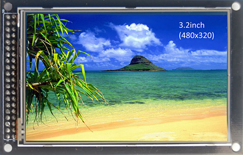
- TFT display: after much deliberation, the Coldtears Electronics 3,2 '' advanced version of the display was chosen, featuring an increased resolution (480x320 instead of 320x240 on most similar displays) and additional functionality (this display has built-in Flash-memory, which are sewn into additional fonts and icons, which allows you to refuse to download additional fonts, thereby saving the controller's precious memory). The display is equipped with an ILI948 controller. The card also has an SD card slot.
- Special Schild for connecting the display to the controller Arduino DUE. This shield allows you to connect the display via a 16-bit parallel interface, and Flash memory through an Arduino ISP connector, which, according to the developers, ensures maximum performance. The Schild is also equipped with an SD card slot (by default it is disabled, to enable it, you must close the jumper on the board, but more on that later).
Pay attention, Schild is designed for Arduino DUE. To use the display with the Arduino MEGA, another plate version is needed, equipped with a 5v – 3.3v level converter.
All materials relating to pinout display and CTE plate can be downloaded on the manufacturer's website:
Display: http://coldtears.lin3.siteonlinetest.com/files/3.2b.zip
Schild: http://coldtears.lin3.siteonlinetest.com/files/CTE_DUE_shield.zip
To work with TFT displays, the UTFT library set is used. The most recent versions of these libraries can be found on the developer’s website: http://www.henningkarlsen.com/electronics/
After connecting the display, the following pins of the controller remain free: D0, D1, D8, D11-D13, D14-D24, D29-D31, D41-D43, A0-A11, DAC0, DAC1, SCL1, SDA1, which can be used at your discretion.
1. Basic UTFT library. General information
The UTFT library is designed to work with TFT displays of various types, connected both via a parallel (8bit or 16bit) and serial interface. It was originally developed to support displays made by ITead Studio and NKG Electronics, but then it was supported by several other manufacturers. The original library can be downloaded here: http://www.henningkarlsen.com/electronics/library.php?id=51
The library comes with pretty good documentation in English. This article is based mainly on developer documentation with the addition of a certain amount of practical experience and additional information that was obtained in the course of work.
')
A list of displays supported by the library and their main features are provided in the accompanying document “UTFT Supported display modules & controllers”, which is supplied with the library.
This library is basic and contains only the main display functionality. There are several additions to it that implement additional functions, such as control using the touch screen (U_Touch), working with on-screen buttons (UTFT_Buttons), an extended set of functions for drawing graphic primitives (UTFT_Geometry), using built-in fonts and icons in some displays (UTFT_CTE), etc.
The base library allows you to work with loadable fonts. Fonts are stored as data arrays, which are placed in separate files and connected to the program text.
2. Getting started with the library
The library can be used both with controllers based on AVR platform (Arduino MEGA), and with controllers on ARM platform (Arduino DUE). Before you start using the library with an Arduino DUE controller, you need to go to the folder where the library is installed: _ARDUINO_FOLDER_ / libraries / UTFT, find the folder / hardware / arm and the file HW_ARM_defines in it. In this file you need to uncomment the line:
#define CTE_DUE_SHIELD 1The UTFT library also has a useful "trick" that allows you to disable the initialization codes of those display models that are not currently in use. This saves some amount of memory (for example, my compiled program size has decreased by almost 12 Kb). To do this, open the memorysaver.h file in the editor located in the root folder of the library and uncomment the lines with the names of those controllers that you do not plan to use in your project. At the same time, only one controller should be commented out - the one you use. Our display, as mentioned above, is equipped with an ILI9481 controller. Therefore, the line:
//#define DISABLE_ILI9481 1 // CTE32HRwe leave it commented out, and in the remaining lines we delete all the characters // at the beginning of the lines. Now you can work.
The use of a library in a project begins with its loading and initialization. Initialization parameters depend on the type of display used. We load the UTFT base library and create an object - a display named myGLCD. Parameters - display model identifier and pin numbers to which RS, WR, CS, RST and ALE lines are connected. These parameters should be found out from the display manufacturer or selected by the list of supported displays that comes with the library.
In our version, a 3.2 ”display with a resolution of 480x320 and an ILI9481 controller manufactured by Coldtears electronics is referred to as the CTE32HR. In this case, according to the Schild scheme, control lines are connected to pins 25-28.
#include <UTFT.h>UTFT myGLCD(CTE32HR,25,26,27,28);Next, you need to connect external fonts (we will not use the built-in fonts of the display yet - this is a topic for another conversation). The library comes with three basic fonts. Here is the ad string for these fonts:
extern uint8_t SmallFont[];extern uint8_t BigFont[];extern uint8_t SevenSegNumFont[];So, we connected and initialized the library, attached the fonts, now we need to initialize our display in the void setup () procedure:
void setup() {myGLCD.InitLCD();myGLCD.clrScr();}The InitLCD () command allows you to set the vertical or horizontal orientation of the display. By default (if the command is invoked without a parameter) the horizontal orientation is set. The clrScr () command; just clears the display. Note that the library does not have the concept of the background color of the entire display. After cleaning, the display always turns black.
Finally, before we move on to a detailed review of the library commands, finish our simplest example — choose the BigFont font and print the traditional “Hello, world!” In the center of the top line of the display:
void loop() {myGLCD.setFont(BigFont);myGLCD.print("Hello, world!",CENTER,0);}3. Library Commands
When working with the library, you need to install it in the folder with the Arduino libraries and connect using the directive:
#include <UTFT.h>The description of the teams is taken mainly from the English manual supplied with the library, and is significantly complemented by practical observations and examples. So…
UTFT - creates a base display class with the specified name, specifies the model identifier and the connection method as parameters.
Two options are possible: for models with a parallel interface, the command is:
UTFT _NAME_ (model, RS, WR, CS, RST, ALE) where _NAME_ is an arbitrary display object name that will be used as a prefix for any access to it, model is a specific display model identifier (see the list of supported models) , and RS, WR, CS, RST and ALE are pin numbers to which the corresponding control signals of the display module are connected by means of the nameplate. Not all supported models have an ALE signal, if your model does not have one, just skip this parameter.For models with a serial interface, the command is:
UTFT _NAME_ (model, SDA, SCL, CS, RST, RS) where SDA, SCL, CS, RST and RS are pin numbers to which the corresponding signals of the serial interface are connected. The RS parameter is optional, for some display models it is not specified.The string with this command is placed in the definition area and must precede any other library commands. The specified display name should be used as a prefix to all subsequent library commands.
InitLCD - initializes the display and sets the horizontal or vertical orientation. The orientation identifier is specified as a parameter.
Being set without parameters, the command sets the horizontal orientation. If you specify the PORTRAIT parameter or 0, the vertical orientation will be selected, if you specify LANDSCAPE or 1 is horizontal.
In the horizontal orientation, the connectors of the controller are located on the left, with the vertical - at the bottom. Other options are not provided. Setting a parameter other than 0 and 1 as a parameter results in a distorted display of information.
This command is usually used in the void setup () section, but it can also be used in the main program loop, as, for example, here:
#include <UTFT.h> UTFT myGLCD(CTE32HR,25,26,27,28); extern uint8_t BigFont[]; void setup() { } void loop() { myGLCD.InitLCD(1); myGLCD.setFont(BigFont); myGLCD.print("Hello, world!",CENTER,0); delay(1000); myGLCD.InitLCD(0); myGLCD.setFont(BigFont); myGLCD.print("Hello, world!",CENTER,0); delay(1000); } In principle, by attaching a position sensor to the display, it would be possible to arrange a screen flip as in a tablet;)) however, during initialization the display flashes white for a short time, which spoils the impression. ;)
This command sets the background color to black, the text color to white, resets the font name used to “none”, and the result of the work of all print commands becomes unpredictable until the font is explicitly set (see the setFont command). After initialization, it is recommended to clear the display (see the clrScr command), and the screen will be filled with black.
clrScr - clears the display, erasing all information displayed on the display and filling the display with black color. It has no parameters.
When cleaning the display, the specified background color (see the setBackColor command) is not reset and remains the same, but the display is still filled with black. In order to clear a display with a different background color, use the fillScr command. The clrScr command is illustrated by the following example:
#include <UTFT.h> UTFT myGLCD(CTE32HR,25,26,27,28); extern uint8_t BigFont[]; void setup() { myGLCD.InitLCD(); delay(1000); myGLCD.setBackColor(0,255,0); myGLCD.clrScr(); delay(1000); myGLCD.setFont(BigFont); myGLCD.print("FFFFFFFF", CENTER,0); } void loop() { } After the controller is reset, the display is initialized, then after 1 second cleaning (the display turns black) and after another second, the characters are displayed, and we see that the background color set before cleaning has not changed.
Before considering the following several commands, it is necessary to consider the specifics of specifying colors in library commands.
Color coding system
The colors in the library are defined in several ways. The internal format of the color data is RGB565. In this format, color is encoded with a 16-bit value, in which the level of red and blue is encoded by five bits, and green by six. Most of the library commands working with color take values that are given as three numbers separated by a comma. Each of these numbers is responsible for the level of the corresponding color (R, G, B). Valid values for each number are from 0 to 255.
Thus, the colors are specified by the user in the RGB888 format, and RGB565 is used inside the library. Format conversion is performed within the library using the following formula:
word color = ((r&248)<<8 | (g&252)<<3 | (b&248)>>3);where color is the color value in RGB565 format, and r, g, and b are user-defined color values. It is in this format that values and all functions for determining the current color are returned.
When specifying colors, it is necessary to take into account that not all combinations of the specified values of r, g, and b will produce different colors. Therefore, for example, the red level values of 255 and 253 give the same red level. The program below displays the maximum and minimum values of r, g, and b valid for the color specified in the program in the color settings commands. To perform the calculation, substitute in the parameters of the myGLCD.setBackColor command decimal values of r, g and b for the selected color, compile and run the program. The display shows the color code in the RGB565 system, returned by the function myGLCD.getBackColor, as well as the minimum and maximum values of r, g, and b, which allow to obtain this color.
#include <UTFT.h> UTFT myGLCD(CTE32HR,25,26,27,28); extern uint8_t BigFont[]; void setup() { myGLCD.InitLCD(); myGLCD.clrScr(); myGLCD.setFont(BigFont); } void loop() { myGLCD.setBackColor(245,34,112); myGLCD.setColor(VGA_NAVY); word CurrentColor=myGLCD.getBackColor(); byte R_1 = highByte(CurrentColor)>>3; byte R_min = R_1<<3; byte R_max = R_min|7; byte G_1 = highByte(CurrentColor)<<5; G_1 = G_1>>2|lowByte(CurrentColor)>>5; byte G_min = G_1<<2; byte G_max = G_min|3; byte B_1 = lowByte(CurrentColor)<<3; B_1 = B_1>>3; byte B_min = B_1<<3; byte B_max = B_min|7; myGLCD.print("GetColor", 0,0); myGLCD.print("RGB888 Min", 0,36); myGLCD.print("RGB888 Max", 0,54); myGLCD.printNumI(CurrentColor, 162,0); myGLCD.printNumI(R_min, 162,36); myGLCD.printNumI(R_max, 162,54); myGLCD.printNumI(G_min, 212,36); myGLCD.printNumI(G_max, 212,54); myGLCD.printNumI(B_min, 262,36); myGLCD.printNumI(B_max, 262,54); } Some standard colors can be set using identifiers:
VGA_BLACK - black,
VGA_SILVER - silver
VGA_GRAY - gray
VGA_WHITE - white
VGA_MAROON - red-brown
VGA_RED - red
VGA_PURPLE - Magenta
VGA_FUCHSIA - Fuchsia
VGA_GREEN - green
VGA_LIME - Lime
VGA_NAVY - dark blue
VGA_BLUE - blue
VGA_TEAL - blue-green
VGA_AQUA - sea wave
If you want to find out the RGB codes for these colors - substitute the color identifier instead of three numbers into the myGLCD.setBackColor command in the above program, after compiling and running, the display will show the necessary codes.
So, we will continue the consideration of the library commands:
fillScr - clears the display, erasing all the information displayed on the display and filling it with the specified background color as a parameter.
The background color is defined by three numbers or a color identifier, for example, like this:
fillScr(0,0,0); //fillScr(255,255,255); //fillScr(255,128,0); //fillScr(VGA_RED); //This command, like clrScr, does not change the specified background color for print commands, therefore, when printing on a display filled with the specified color, the background color must also be specified (see the setBackColor command).
setColor - sets the ink color for all commands for printing and drawing graphic primitives. The parameter indicates the desired color.
Colors are set the same way as for the fillScr command — either numbers or standard color identifiers. Example:
#include <UTFT.h> UTFT myGLCD(CTE32HR,25,26,27,28); extern uint8_t BigFont[]; void setup() { myGLCD.InitLCD(); myGLCD.clrScr(); myGLCD.setFont(BigFont); } void loop() { myGLCD.setColor(VGA_RED); myGLCD.print("Hello, World!",CENTER,0); myGLCD.setColor(VGA_NAVY); myGLCD.print("Hello, World!",CENTER,18); myGLCD.setColor(VGA_TEAL); myGLCD.print("Hello, World!",CENTER,36); myGLCD.setColor(VGA_LIME); myGLCD.print("Hello, World!",CENTER,54); while(1); } setBackColor - sets the background color for print commands. The parameter indicates the desired color.
Colors are set in the usual way - by numbers or identifiers (see the fillScr command), however, there is another identifier for this command - VGA_TRANSPARENT, which allows printing characters on a “transparent” background.
If you need to print on a display filled with any color other than black, you must set the exact same background color with the setBackColor command, or use the setBackColor (VGA_TRANSPARENT) command.
getColor - returns the current ink color value. It has no parameters.
getBackColor - returns the current value of the background color. It has no parameters.
These two functions return a word value corresponding to the currently specified color in RGB565 format. This value can be passed as a parameter in the setColor, SetBackColor and fillScr commands like this:
setColor(32586);This command gives the same color as setColor (120,232.80) or setColor (125,233,84), as can be seen with the RGB565 color decoding program discussed above.
getDisplayXSize - returns the width of the display in pixels at the selected orientation. It has no parameters.
getDisplayYSize - returns the value of the display height in pixels at the selected orientation. It has no parameters.
These two functions can be illustrated by the following example:
#include <UTFT.h> UTFT myGLCD(CTE32HR,25,26,27,28); extern uint8_t BigFont[]; void setup() { } void loop() { myGLCD.InitLCD(PORTRAIT); myGLCD.setFont(BigFont); myGLCD.clrScr(); myGLCD.print("Screen Width=",0,0); myGLCD.printNumI(myGLCD.getDisplayXSize(),250,0); myGLCD.print("Screen Height=",0,18); myGLCD.printNumI(myGLCD.getDisplayYSize(),250,18); delay(2000); myGLCD.InitLCD(LANDSCAPE); myGLCD.setFont(BigFont); myGLCD.clrScr(); myGLCD.print("Screen Width=",0,0); myGLCD.printNumI(myGLCD.getDisplayXSize(),250,0); myGLCD.print("Screen Height=",0,18); myGLCD.printNumI(myGLCD.getDisplayYSize(),250,18); delay(2000); } When the program starts (vertical orientation is set), the display width will be equal to 320 pixels, and its height will be 480, after 2 seconds the orientation will change to horizontal and will become equal to 480 pixels, and will be 320 in height.
Before considering the print commands and working with fonts, it is necessary to elaborate on the methods of using fonts in the UTFT library.
External fonts for print commands.
External fonts are stored in separate files with the extension .c and represent arrays of data containing information about font parameters and encoded graphic images of characters.
The font is connected with the string "extern uint8_t _NAME_SHIFT_;". The extern qualifier indicates that the array with the font data is in another file, and the font name is taken from the font file. Please note that this is not the name of the file, but the name of the font itself (they may differ). Fonts used must be declared in your program using the extern specifier. For example:
extern uint8_t BigFont[];The library comes with three main fonts:
- SmallFont - 95 characters 8x12
- BigFont - 95 characters 16x16
- SevenSegNumFont - 10 numeric characters 32x50
Font SevenSegNumFont simulates a 7-segment digital indicator.
Additional fonts can be found here:
http://www.henningkarlsen.com/electronics/r_fonts.php
And here is an online service that allows you to create your own fonts from specially prepared graphic files:
http://www.henningkarlsen.com/electronics/t_make_font_file.php
The fonts included in the library bundle are stored in the DefaultFonts.c file in the root folder of the library. Additional fonts (drawn by yourself or downloaded from the above link) are recommended to be placed in the folder of your project, otherwise the compiler may not find them.
Font files are definitions of arrays containing service information and an encoded graphic image of a font. In addition to the title, the comments inside the font file also contain information on the size of the character in pixels (this information will be useful when setting the text display coordinates), the amount of memory occupied by the font data array and the number of characters specified in this font. There are "full" fonts of 95 characters, "digital" (10 characters) and "subsets" (a different number of characters).
The first 4 bytes of the array contain service information:
Byte 0 - horizontal font size in pixels
Byte 1 - vertical font size in pixels
Byte 2 is the code of the first character of the font (for “full” fonts, this is 0x20, that is, the space code, for “digital” - 0x30 - the character code “zero”).
Byte 3 - the number of characters of the font (for "full" fonts 0x5F, for "digital" - 0x0A).
More information about the subtleties of the format and creating custom fonts can be found here: http://www.henningkarlsen.com/electronics/h_utft_fonts_101.php
If you plan to work with large figures stylized as a 7-segment indicator, we recommend immediately replacing the SevenSegNumFont font with the alternative SevenSegNumFontPlus font, which can be downloaded here:
http://www.henningkarlsen.com/electronics/dlfont.php?id=21&t=c
it is distinguished by the presence of a very useful “:” character, which is not in the standard font. The font file should be placed in the folder with your program, replace the ad extern uint8_t SevenSegNumFont []; on extern uint8_t SevenSegNumFontPlus []; then close and reopen the project. The font file should open with the project in the adjacent tab.
setFont - sets the font for print commands. Font name is passed as a parameter.
The font must be previously declared in the program definition area. Example:
#include <UTFT.h> UTFT myGLCD(CTE32HR,25,26,27,28); extern uint8_t SmallFont[]; void setup() { myGLCD.InitLCD(); myGLCD.setFont(SmallFont); myGLCD.clrScr(); myGLCD.print("Hello, World!",0,0); } void loop() {} getFont - returns a pointer to the address of the current font in the memory of the controller.
Consider an example. Slightly above, we already said that the first four bytes in the font data array contain information about the font properties. This information for the current font can be obtained directly from the memory of the controller and used in the program. The following program places in variables and displays the size of the character in pixels, the code of the first character and the number of characters of the current font specified by the setFont command.
#include <UTFT.h> UTFT myGLCD(CTE32HR,25,26,27,28); extern uint8_t BigFont[]; void setup() { myGLCD.InitLCD(); myGLCD.clrScr(); myGLCD.setFont(BigFont); SerialUSB.begin(9600); } void loop() { uint8_t* FontAddr = myGLCD.getFont(); byte CurrentFontX = *FontAddr; byte CurrentFontY = *(FontAddr+1); byte CurrentFontStartCode = *(FontAddr+2); byte CurrentFontSymNumber = *(FontAddr+3); myGLCD.printNumI(CurrentFontX, 0,0); myGLCD.printNumI(CurrentFontY, 0,18); myGLCD.printNumI(CurrentFontStartCode, 0,36); myGLCD.printNumI(CurrentFontSymNumber, 0,54); Similarly, you can access any byte of the current font.
getFontXsize - returns the horizontal size (width) of the character of the current font in pixels. It has no parameters.
getFontYXsize - returns the vertical size (height) of the character of the current font in pixels. It has no parameters.
These functions can be useful in calculating coordinates for print commands. Examples of using these functions for calculating coordinates are given in the description of print commands.
Next, we consider several commands designed to display symbolic information, that is, print commands.
print - displays the text, the contents of a character variable or an object of type String. The output text, the coordinates of the upper left corner of the printable area are passed as parameters. Another optional parameter allows positioning a printable line with a given slope.
This command is designed to display textual information. Print coordinates X and Y are specified in pixels and can be passed either explicitly or via integer variables or expressions. There are also three predefined identifiers for use as the X coordinate:
- LEFT - the text is aligned to the left of the display.
- CENTER - text is centered on the display.
- RIGHT - text is aligned to the right edge of the display.
Text information can be represented as a string enclosed in double quotes:
myGLCD.print("Hello, World!", 0,0);or as a variable of type String:
String text = "Hello, World!";myGLCD.print(text, 0,0);or as the result of a function that returns a string value:
int valueInt = 12345;myGLCD.print(String(valueInt), 0,0);float valueFloat = 12345.67;myGLCD.print(String(valueFloat), 0,18);Coordinates are set individually for each invocation of the command, the current position of the print is not returned by the command. Therefore, you need to independently calculate the position for the next print command. This can be done in a fairly simple way. The following example prints two string values in a row on one line (without a space):
#include <UTFT.h> UTFT myGLCD(CTE32HR,25,26,27,28); extern uint8_t BigFont[]; void setup() { myGLCD.InitLCD(); myGLCD.clrScr(); myGLCD.setFont(BigFont); } void loop() { int X=0; int Y=0; int valueInt1 = 12345; myGLCD.print(String(valueInt1), X,Y); X=X+myGLCD.getFontXsize()*String(valueInt1).length(); int valueInt2 = 67890; myGLCD.print(String(valueInt2), X,Y); } To separate output values by a space, the calculated value of X must be increased by the width of one character. And here the printing is carried out in two lines:
#include <UTFT.h> UTFT myGLCD(CTE32HR,25,26,27,28); extern uint8_t BigFont[]; void setup() { myGLCD.InitLCD(); myGLCD.clrScr(); myGLCD.setFont(BigFont); } void loop() { int X=0; int Y=0; int valueInt1 = 12345; myGLCD.print(String(valueInt1), X,Y); Y=Y+myGLCD.getFontYsize(); int valueInt2 = 67890; myGLCD.print(String(valueInt2), X,Y); } LEFT, CENTER RIGHT : #include <UTFT.h> UTFT myGLCD(CTE32HR,25,26,27,28); extern uint8_t BigFont[]; void setup() { myGLCD.InitLCD(); myGLCD.clrScr(); myGLCD.setFont(BigFont); } void loop() { int Y=60; myGLCD.print("Hello, World!", LEFT, Y); Y=Y+myGLCD.getFontYsize(); myGLCD.print("Goodbye, World!", LEFT,Y); Y=Y+myGLCD.getFontYsize()*4; myGLCD.print("Hello, World!", CENTER, Y); Y=Y+myGLCD.getFontYsize(); myGLCD.print("Goodbye, World!", CENTER,Y); Y=Y+myGLCD.getFontYsize()*4; myGLCD.print("Hello, World!", RIGHT, Y); Y=Y+myGLCD.getFontYsize(); myGLCD.print("Goodbye, World!", RIGHT,Y); } Another optional parameter allows you to print lines inclined at an angle from 0 to 359 degrees. Rotation is set relative to print coordinates (upper left corner). The zero value of the angle leads to the usual horizontal printing, then as the angle increases, the text rotates clockwise by a given angle. The following example allows you to get a funny graphic effect:
#include <UTFT.h> UTFT myGLCD(CTE32HR,25,26,27,28); extern uint8_t BigFont[]; void setup() { myGLCD.InitLCD(); myGLCD.clrScr(); myGLCD.setFont(BigFont); } void loop() { int X=240; int Y=160; for (int DEG=0; DEG<360; DEG+=20) { String text = "Hello, World!"; myGLCD.print(text, X,Y, DEG); } } When printing text at an angle using the predefined identifiers LEFT, CENTER and RIGHT is not recommended, because they can not be adequately computed by the library. That is, the alignment is still calculated as if the line is printed horizontally, and the rotation is carried out after alignment and is still relative to the upper left corner of the print area.
By the way, print commands do not know how to determine the output outside the display. So the maximum line length will have to be monitored independently. If the line is too long, then its "tail" can be displayed over the already printed text. If you get out of the bottom of the display, the result may be unpredictable.
printNumI - displays an integer or the contents of an integer variable. As parameters, the displayed value and the coordinates of the upper left corner of the printable area are transferred. Optional parameters allow you to control the output format.
Print coordinates are set the same as for the print command. When printing signed numbers at position X, the number sign is displayed, and then the first digit. When printing unsigned numbers or positive values, the first digit of the number is displayed at position X.
#include <UTFT.h> UTFT myGLCD(CTE32HR,25,26,27,28); extern uint8_t BigFont[]; void setup() { myGLCD.InitLCD(); myGLCD.clrScr(); myGLCD.setFont(BigFont); } void loop() { byte X=100; byte Y=10; int Num1 = 1234; int Num2 = -1234; unsigned int Num3= 12345; myGLCD.printNumI(Num1,X,Y); Y=Y+myGLCD.getFontYsize(); myGLCD.printNumI(Num2,X,Y); Y=Y+myGLCD.getFontYsize(); myGLCD.printNumI(Num3,X,Y); } A printed value can be passed as an integer:
myGLCD.printNumI(1250,0,0);or a variable of one of the integer types:
int Num = 1324;myGLCD.printNumI(Num,0,0);It is also possible to output the result of any function or expression, which is an integer value:
myGLCD.printNumI(myGLCD.getFontYsize()*2,0,0);When working with integer values, you must remember that in Arduino DUE, the int type is stored as type long as a 4-byte number with a range of valid values from –2,147,483,648 to 2,147,483,647.
The unsigned int and unsigned long types are not supported by the printNumI command, i.e. the value can be transferred to the command, but will be displayed as a signed number. The type char is on the contrary treated as unsigned.
Additional optional parameters of this command allow you to set the format of the output numbers. The length parameter defines the minimum number of familiarity (including the sign of the number) occupied by the displayed number on the display. If the number of digits of the number is less than the specified value of length, the missing number of familiarity is supplemented on the left with the required number of characters. The filler parameter allows you to specify a character (the default is a space), which will be supplemented with a number. The combination of these symbols makes it possible, in particular, to organize the output of numbers aligned on the right border or to supplement with insignificant zeros of values when displaying a time or date. That is, instead of the usual design:
byte Day = 2;byte Month = 9;int Year = 2013;if (Day<10){myGLCD.print("0",0,0);myGLCD.printNumI(Day,16,0);}else{myGLCD.printNumI(Day,0,0);}myGLCD.print(".", 32,0);if (Month<10){myGLCD.print("0",48,0);myGLCD.printNumI(Month,64,0);}else{myGLCD.printNumI(Month,48,0,2,'0');}myGLCD.print(".", 80,0);myGLCD.printNumI(Year,96,0);you can simply write:
byte Day = 2;byte Month = 9;int Year = 2013;myGLCD.printNumI(Day,0,0,2,'0');myGLCD.print(".", 32,0);myGLCD.printNumI(Month,48,0,2,'0');myGLCD.print(".", 80,0);myGLCD.printNumI(Year,96,0);isn't it so much better?
printNumF - displays a real number or the contents of a real type variable. As parameters, the displayed value, the number of digits after the decimal point and the coordinates of the upper left corner of the print area are transferred. Optional parameters allow you to control the output format.
Print coordinates are set in the same way as in other print commands. The displayed real value can be specified as a number, as a variable of a real type (float), and also as a function that returns a real result or expression, the result of which is a real number.
The number of digits after the decimal point can be set from 1 to 5. A zero value is not allowed (in this case, it is recommended to convert the number to an integer type and use the printNumI command). For example, the command:
myGLCD.printNumF(-234.3442, 2, 0, 0);allows you to display the number –234.34.
The number can be specified both in exponential form and in floating point format, while the output will be carried out in floating point format. For example, two commands:
myGLCD.printNumF(-2.343442E2, 2, 0, 0);myGLCD.printNumF(-234.3442, 2, 0, 0);Display the same value –234.34. The
optional divider parameter allows you to redefine the character that plays the role of a decimal point (the default is '.'). For example, the command:
myGLCD.printNumF(-234.3442, 2, 0, 0, ',');allows you to replace the decimal point symbol with a comma. In this case, of course, you must still enter numbers in the program using a dot. Replacing only affects the output.
The optional parameters length and filler work similarly to the printNumF command, allowing you to control the minimum number of characters when displaying a number. The length parameter takes into account all familiarities occupied by the displayed number, including the sign, integer part, decimal point and fractional part. For example, the command:
myGLCD.printNumF(-234.3442, 2, 0, 0, '.', 10, '0');displays the number –000234.34 (the initial number, supplemented by three insignificant zeros so that the total number of familiarity is 10).
ATTENTION!When using the optional parameter length, the divider parameter must be specified, otherwise the system will try to interpret the length value as the character code of the separator, which can lead to unpredictable results.
We now turn to a group of commands that allow you to display graphic primitives on the display - points, lines, rectangles and circles.
drawPixel - displays a point. The color of the point is determined by the current color value set by the setColor () command.
The coordinates X and Y are passed as parameters.
Parameters can be given by numbers, variables, results of functions or expressions. Parameters can be a real number, but the fractional part will be discarded. You must also make sure that the coordinates of the point do not go beyond the display, otherwise the point may not be where you expect to see it;) You can use the getDisplayXsize () and getDisplayYsize () functions discussed earlier to control the display outside the display.
An example of using the drawPixel command — the following construction displays a sinusoid constructed from individual points:
for (int x=0; x<48; x++) {int y=(sin(x)*10)+100;myGLCD.drawPixel(x*10,320-y);The following group of commands require as parameters the coordinates of two points that determine the size of the figure being drawn.
drawLine - displays the line given by the coordinates of the start and end points.
The line drawing direction depends on the location of the start and end points. For example, the line:
myGLCD.drawLine(10,20,100,200);draws the line between the points with coordinates X = 10, Y = 20 for the first point and X = 100, Y = 200 for the second one with the current color. Line:
myGLCD.drawLine(100,200,10,20);draws exactly the same line between the same points, but the direction of drawing will be opposite.
drawRect - displays a rectangle defined by the coordinates of two opposite corners.
Coordinates are set the same as for the drawLine command.
drawRoundRect - displays a rectangle with rounded corners, given by the coordinates of two opposite corners.
The minimum size of the sides of the rectangle is limited to 5 pixels. When specifying the sides of a smaller size, the rectangle cannot be displayed.
fillRect - displays a filled rectangle defined by the coordinates of two opposite corners.
The rectangle is drawn and filled with the current color.
fillRoundRect — displays a filled rectangle with rounded corners, given by the coordinates of two opposite corners.
This command functions the same as the drawRoundRect command.
The following two commands are designed to draw circles and circles and require three parameters: the X and Y coordinates of the center of the circle (or circle) and radius.
drawCircle - displays a circle defined by the coordinates of the center and radius.
The radius of the circle should not take negative values, since in this case it will be displayed incorrectly.
The following command displays a circle with a radius of 50 pixels and a center at a point with coordinates X = 100 and Y = 120:
drawCircle(100,120,50);fillCircle - displays a circle filled with the current color, defined by the coordinates of the center and radius.
At negative radius values the circle is not displayed.
So, we looked at drawing commands for graphic primitives. By the way, for the UTFT library there is the addition UTFT_Geometry, which allows you to display triangles (contour and filled), arcs of circles and a sector of circles. We will look at the work with this supplement in one of the following articles.
And now there are quite a few: two commands that allow you to display a specially prepared bitmap image:
drawBitmap - displays a specially prepared bitmap graphic image.
The parameters are the coordinates of the upper left corner of the image, its dimensions and the name of the array in which the encoded image is stored.
The optional scale parameter allows you to control the scaling of the image when displayed.
The image for this command is prepared using the special utility ImageConverter565.exe, which comes with the library and is located in the Tools folder. And here you can use the online image conversion service:
http://www.henningkarlsen.com/electronics/t_imageconverter565.php
Converter can work with jpg, png and gif file formats.
As an example, consider the task of displaying a bitmap image and a text message on its background. Of course, a background image of 480x320 pixels will take up inadmissibly a lot of space in the controller's memory, so we use the image reduced by 2 times (240x160 pixels) and use scaling.
To prepare the image, you must run the ImageConverter565.exe file, and open the file with your image in it. Next, we will set the flag “Reduce size to” and set the required image size (240x160). In the “Save As” switch, select “.c”, and in the “Target Board” switch, select “chipKit / Arduino Due”. In the “Array Name” field, set the name of the image and click “Save”.
As a result of the converter operation, we will receive a file with the .c extension, in which information about the image and the encoded image will be stored. This file must be placed in the folder of your project and declare an array in the program using the extern specifier in the same way as we did for fonts. Only in square brackets it is necessary to indicate the size of the array in hexadecimal format (this value is in the first element of the array, it can be viewed by opening the file obtained as a result of the conversion in any text editor).
Do not forget to close and reopen the program file after copying and connecting the array. At that, the file of the array will open on the adjacent tab next to the program text. The text of our program will look like this:
#include <UTFT.h> UTFT myGLCD(CTE32HR,25,26,27,28); extern uint8_t BigFont[]; extern unsigned short background[0x9600]; void setup() { myGLCD.InitLCD(); myGLCD.setColor(0,255,0); myGLCD.setFont(BigFont); myGLCD.setBackColor(VGA_TRANSPARENT); } void loop() { myGLCD.drawBitmap (0,0, 240, 160, background,2); myGLCD.print("Hello, World!", CENTER,50); while(1); } Thus, we set the output to the upper left corner of the display of the image placed in the array named 240 240 pixels in size, but since we used the scale parameter equal to two, the picture will be stretched across the entire display. Next, on top of the image using the “VGA_TRANSPARENT” parameter, which ensures the “transparency” of the background during printing, we display a text message. Pretty wasteful - about 100kb just one image, but beautiful;)
Another form of invoking this command with additional parameters is possible, allowing you to rotate the image at a given angle. Parameters in this case should be three: deg - angle of rotation of the image rox - X coordinate of the center of rotation, roy - Y-coordinate of the center of rotation. The angle of rotation is set in degrees (from 0 to 359), and the coordinates of the center of rotation rox and roy are measured from the upper left corner of the picture. Consider an example.For the image, we use the info.c file that comes with the library (it is located in the / examples / Arduino (ARM) / UTFT_Bitmap root folder of the library subfolder). The size of the image is 32x32 pixels, the volume of the array is 0x400. The following program will display a picture rotating around its axis:
#include <UTFT.h> UTFT myGLCD(CTE32HR,25,26,27,28); extern uint8_t BigFont[]; extern unsigned short info[0x400]; void setup() { myGLCD.InitLCD(); myGLCD.fillScr(VGA_WHITE); } void loop() { for (int R=0; R<360; R+=10){ myGLCD.drawBitmap (100,100, 32, 32, info,R,16,16); } } Unfortunately, simultaneous rotation and scaling are not possible.
And finally, a few more commands:
lcdOff - disables the display. It has no parameters.
lcdOn - turns on the display. It has no parameters.
After executing the lcdOff () command, the display turns off and does not respond to any commands until the lcdOn () command is executed.
According to the developer’s statement, these two commands are implemented only for displays with a PCF8833 controller, so they are simply ignored on our display.
setContrast - sets display contrast. Parameter - the amount of contrast.
As a parameter, a conditional value is defined that defines the display contrast: from 0 (minimum contrast) to 64 (maximum contrast).
This command is also implemented only for displays with a PCF8833 controller, so no contrast changes will occur on our display and the command will be ignored.
Conclusion
So, we have learned to use all the commands of the UTFT base library. In the following articles we will talk about additions to this library, allowing to expand its capabilities. The next step is drawing triangles, arcs and sectors, working with a touch screen, as well as working with text and graphic buttons on the display, controlled by a touch screen. In the future, we plan to consider the built-in capabilities of our display - working with the internal memory of the display module, with its fonts and icons sewn into its ROM.
Source: https://habr.com/ru/post/196600/
All Articles