We are finishing the Turnigy Accucel 6 charger
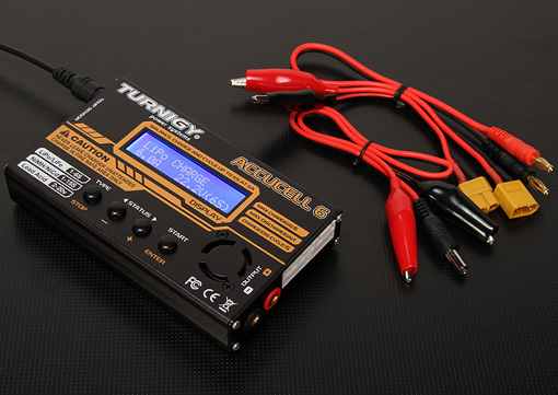
Many people know the universal iMax B6 charger and its Turnigy Accucel 6 clone.
It can charge
But that is not all. The charger can be connected to the computer and get visual charts of charging / discharging the batteries, visually assessing on the graph what voltage range the main part of the charge is concentrated on, how the battery reacts to different charging and discharge currents, how much the voltage drops under the load, and much more.
That's just from the factory, this charge has been going for a couple of years without such an opportunity. The manufacturer was greedy and did not put a couple of chips and kopek elements, and the manufacturer iMax B6 generally sells lace and software separately at a price comparable to the charging itself.
Normally on the left side there is a 3-pin connector for connecting a temperature sensor or connecting to a computer. In the instructions, the functionality is described as a USB connection, but there is no USB at all - in the first versions the UART was brought there, but after trying to connect to it, I found out that now it is not connected either. Some iMAX B6 models come with a miniUSB connector, but I haven’t met Accucel 6 in this design, although the motherboard has space for a connector and the chips serving it are divorced.
The cord sold with the software is designed for this pinout:
But, unfortunately, food and earth are in place, but Tx pin is not connected.
Having thoroughly rummaged in the internet, I found information that now the pin is not connected, but this can be fixed.
For this you need only a couple of parts, a piece of wire and a soldering iron.
We disassemble the case by removing the top two screws from each end and carefully remove the front panel. Carefully disconnect the fan from the motherboard. Unscrew the 3 screws that secure the board to the bottom and remove the board.

I casually stuck a couple of layers of blue electrical tape on a squeaker so that I wouldn't scream so loudly.
On the reverse side of the board in the lower right corner you can see that some of the parts are not decoupled.
We will need:
Chip resistors of standard size 0805 on 10 kOhm and 100 kOhm 1 piece each and diode 1n4144 in mini-MELF package. This is necessary in order to preserve the ability to connect to the USB and temperature sensor and not burn anything, forgetting to switch functionality.
I do not have a thermal sensor, so I put only a pair of resistors (there was no suitable diode size).
The photo shows where you need to solder the resistors (clickable).

Upper - 10kOhm, lower 100kOhm.
From the right contact of the resistor with a nominal value of 10kΩ we throw the wiring on the middle pin of the 3-pin connector.
Everything, we collect in the reverse order.
Now you need to switch the connector functionality from the temperature sensor to "USB":
At the top level in the USER SET PROGRAM menu we find the “Temp Cut Off” menu and change to “USB Enable”. This changes the functionality of the port from a temperature sensor to a UART.
Charging set up, now connect to the computer.
We need any USB-UART cable. We connect the GND pins, and the average pin of the charger with the Rx pin of the USB-UART adapter (clickable):

We include charging and we watch favorite terminalka that binary data pour in the port.
The port settings are 9600-8-N-1.
Now you need software. There was no native software on the torrents, the links to the distribution kit were rotten, and I don’t need to buy it and wait until it comes - not our method, especially the cable from the kit.
Fortunately there is a free software - LogView - a powerful thing. The only drawback is that it is not fully translated into English and suffers from a bunch of German terms, but it's easy to understand.
Download, install. Choose English or who is closer - German.
We show to which port the device is connected, choose the device itself as iMax B6 from SkyRC.
If everything is done correctly, the data immediately go - they can be seen on the Serial logging tab at the bottom of the window.
For those who are not friends with German at all, the parameters are:
Spannung - battery voltage
Strom - charge / discharge current
Ladung - injected current in mAh
Energie - charge in Wh * h
Leistung - current power output in watts
Spannung (In) - the voltage at the input of the charger.
The program determines the charge / discharge itself, so you can write the whole process to one file, then select Laden from the drop-down list to view the charge process or Entladen for the discharge graph.
I will not describe all the functionality, I can only say that you can save the interface settings as profiles, which is convenient not to select a bunch of checkmarks every time you create a new file.
')
To record the process of working with the battery, you need to create a new file and continue to work with charging as usual. The device sends data at about 4-5 Hz, software writes to a file at 1 Hz.
On the toolbar a bunch of options for measuring the slope of the curves. Calculations of deltas between points, measurements at the indicated mouse point or in the center of the screen, etc.
That's all. For half an hour of work, we get a great tool for visual analysis of batteries. In addition, you can store the parameters and compare the parameters among themselves over time or different batteries with each other. The corresponding tab is also there.
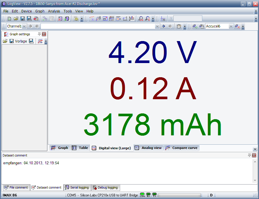
It is still very convenient when charging is at the opposite end of the room, to use a tab with large current values - it is very clearly visible, and the data is much more accurate than on the charging screen.
In general, LogView supports a bunch of other devices, so the farm will come in handy.
It can charge
- Lithium Polymer LiPo and Li-ion LiIon Batteries
- Nickel-cadmium NiCd, so beloved by manufacturers of electric drills
- Ni-MH nickel metal hydride, bundled with low-cost radio controlled models
- Lead Pb, which can be found in the car, Moto, UPS and much more.
But that is not all. The charger can be connected to the computer and get visual charts of charging / discharging the batteries, visually assessing on the graph what voltage range the main part of the charge is concentrated on, how the battery reacts to different charging and discharge currents, how much the voltage drops under the load, and much more.
That's just from the factory, this charge has been going for a couple of years without such an opportunity. The manufacturer was greedy and did not put a couple of chips and kopek elements, and the manufacturer iMax B6 generally sells lace and software separately at a price comparable to the charging itself.
Normally on the left side there is a 3-pin connector for connecting a temperature sensor or connecting to a computer. In the instructions, the functionality is described as a USB connection, but there is no USB at all - in the first versions the UART was brought there, but after trying to connect to it, I found out that now it is not connected either. Some iMAX B6 models come with a miniUSB connector, but I haven’t met Accucel 6 in this design, although the motherboard has space for a connector and the chips serving it are divorced.
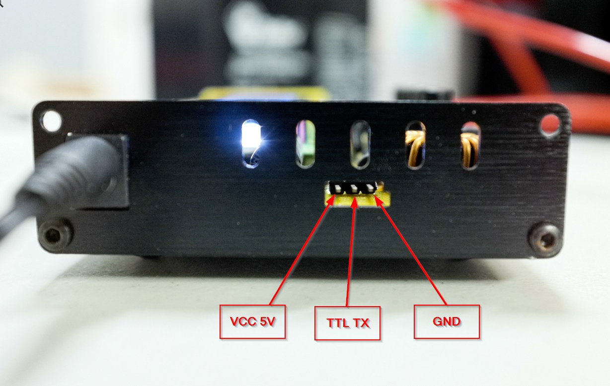
The cord sold with the software is designed for this pinout:
But, unfortunately, food and earth are in place, but Tx pin is not connected.
Having thoroughly rummaged in the internet, I found information that now the pin is not connected, but this can be fixed.
For this you need only a couple of parts, a piece of wire and a soldering iron.
We disassemble the case by removing the top two screws from each end and carefully remove the front panel. Carefully disconnect the fan from the motherboard. Unscrew the 3 screws that secure the board to the bottom and remove the board.
I casually stuck a couple of layers of blue electrical tape on a squeaker so that I wouldn't scream so loudly.
On the reverse side of the board in the lower right corner you can see that some of the parts are not decoupled.
We will need:
Chip resistors of standard size 0805 on 10 kOhm and 100 kOhm 1 piece each and diode 1n4144 in mini-MELF package. This is necessary in order to preserve the ability to connect to the USB and temperature sensor and not burn anything, forgetting to switch functionality.
I do not have a thermal sensor, so I put only a pair of resistors (there was no suitable diode size).
The photo shows where you need to solder the resistors (clickable).
Upper - 10kOhm, lower 100kOhm.
From the right contact of the resistor with a nominal value of 10kΩ we throw the wiring on the middle pin of the 3-pin connector.
Everything, we collect in the reverse order.
Now you need to switch the connector functionality from the temperature sensor to "USB":
At the top level in the USER SET PROGRAM menu we find the “Temp Cut Off” menu and change to “USB Enable”. This changes the functionality of the port from a temperature sensor to a UART.
Charging set up, now connect to the computer.
We need any USB-UART cable. We connect the GND pins, and the average pin of the charger with the Rx pin of the USB-UART adapter (clickable):
We include charging and we watch favorite terminalka that binary data pour in the port.
The port settings are 9600-8-N-1.
Now you need software. There was no native software on the torrents, the links to the distribution kit were rotten, and I don’t need to buy it and wait until it comes - not our method, especially the cable from the kit.
Fortunately there is a free software - LogView - a powerful thing. The only drawback is that it is not fully translated into English and suffers from a bunch of German terms, but it's easy to understand.
Download, install. Choose English or who is closer - German.
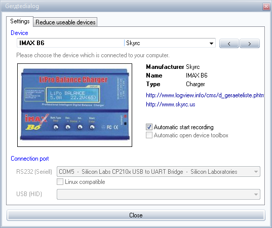
We show to which port the device is connected, choose the device itself as iMax B6 from SkyRC.
If everything is done correctly, the data immediately go - they can be seen on the Serial logging tab at the bottom of the window.
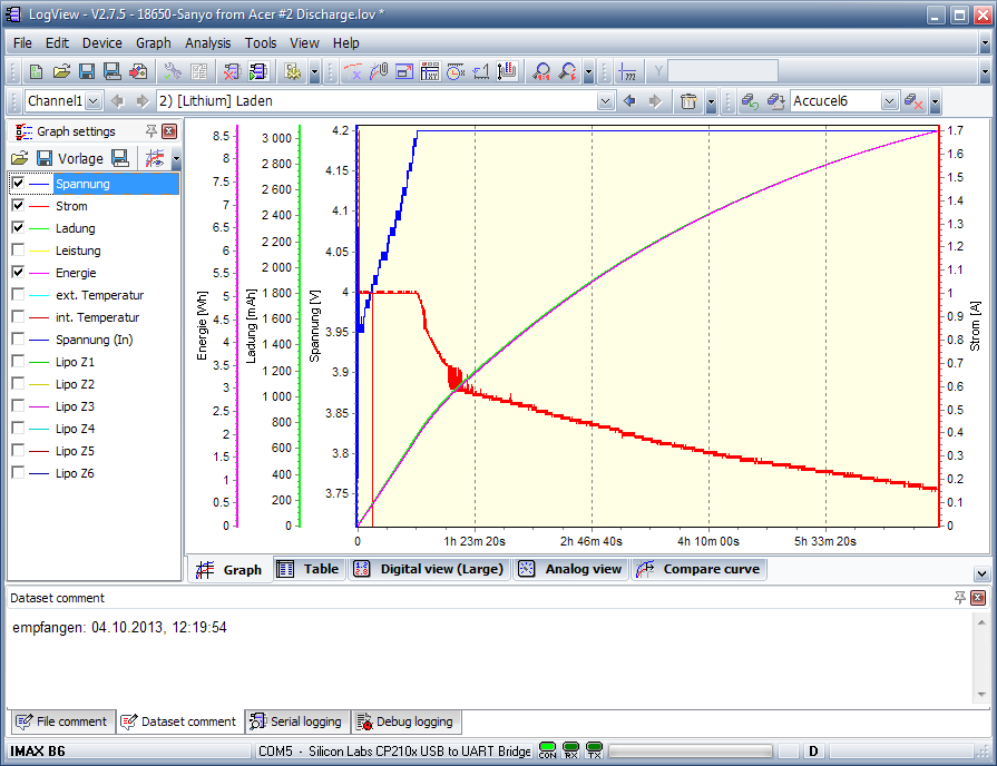
For those who are not friends with German at all, the parameters are:
Spannung - battery voltage
Strom - charge / discharge current
Ladung - injected current in mAh
Energie - charge in Wh * h
Leistung - current power output in watts
Spannung (In) - the voltage at the input of the charger.
The program determines the charge / discharge itself, so you can write the whole process to one file, then select Laden from the drop-down list to view the charge process or Entladen for the discharge graph.
I will not describe all the functionality, I can only say that you can save the interface settings as profiles, which is convenient not to select a bunch of checkmarks every time you create a new file.
')
To record the process of working with the battery, you need to create a new file and continue to work with charging as usual. The device sends data at about 4-5 Hz, software writes to a file at 1 Hz.
On the toolbar a bunch of options for measuring the slope of the curves. Calculations of deltas between points, measurements at the indicated mouse point or in the center of the screen, etc.
That's all. For half an hour of work, we get a great tool for visual analysis of batteries. In addition, you can store the parameters and compare the parameters among themselves over time or different batteries with each other. The corresponding tab is also there.
It is still very convenient when charging is at the opposite end of the room, to use a tab with large current values - it is very clearly visible, and the data is much more accurate than on the charging screen.
In general, LogView supports a bunch of other devices, so the farm will come in handy.
Source: https://habr.com/ru/post/196416/
All Articles