GPS tracker on arduino do it yourself
After several experiments with Arduina, I decided to make a simple and not very expensive GPS tracker with sending coordinates via GPRS to the server.
The Arduino Mega 2560 (Arduino Uno) is used, the SIM900 is a GSM / GPRS module (to send information to the server), a SKM53 GPS receiver.
Everything was purchased on ebay.com, in the amount of about 1500 r (about 500r arduin, a little less - GSM module, a little more - GPS).

First you need to deal with work with GPS. The selected module is one of the cheapest and simplest. Nevertheless, the manufacturer promises the presence of a battery for storing satellite data. According to the datasheet, the cold start should take 36 seconds, however, in my conditions (10th floor from the window sill, there are no buildings close) it took as much as 20 minutes. The next start, however, is already 2 minutes.
')
An important parameter of devices connected to the Arduin - power consumption. If you overload the Arduin converter, it may burn. For the receiver used, the maximum power consumption is 45mA @ 3.3v. Why in the specification to indicate the current strength on a voltage different from the required (5V) is a mystery to me. However, the 45 mA arduine converter will survive.
GPS is not controlled, although it has an RX pin. For what is unknown. The main thing you can do with this receiver is to read the NMEA data from the TX pin. Levels - 5V, just for Arduin, speed - 9600 baud. I connect the VIN to the VCC arduine, GND to GND, TX to RX of the corresponding serial. I read the data first manually, then using the TinyGPS library. Surprisingly, everything is read. After switching to Uno, I had to use SoftwareSerial, and then the problems started - some of the message characters were lost. This is not very critical, since TinyGPS cuts out invalid messages, but rather unpleasantly: you can forget about the frequency in 1 Hz.
A small note about SoftwareSerial: there are no hardware ports on Uno (except connected to USB Serial), so you have to use software. So, he can only receive data on the pin on which the board supports interrupts. In the case of Uno, these are 2 and 3. Moreover, only one such port can receive data at a time.
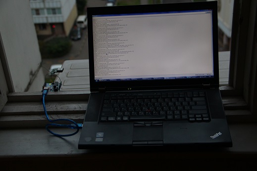
This is what a “test stand” looks like.

Now the more interesting part begins. GSM module - SIM900. It supports GSM and GPRS. Neither EDGE, nor even 3G, are supported. This is probably good for transferring coordinate data - there will be no delays and problems when switching between modes, plus GPRS is almost everywhere now. However, for some more complex applications this may not be enough.
The module is also controlled by a serial port, with the same level - 5V. And here we will need both RX and TX. The module is a shield, that is, it is installed on the arduin. And it is compatible with both mega and uno. The default speed is 115200.
We are going to Mega, and here we are waiting for the first unpleasant surprise: the TX pin of the module falls on the 7th pin of mega. At the 7m pin of the mega, interrupts are not available, which means you have to connect the 7th pin, say, to 6m, at which interruptions are possible. Thus, we will spend one pin of arduin for nothing. Well, for mega it's not very scary - still enough pins. But for Uno it is more difficult (remember, there are only 2 pins supporting interrupts - 2 and 3). As a solution to this problem, it is possible not to install the module on the arduin, but to connect it with wires. Then you can use Serial1.
After connecting, we are trying to “talk” with the module (do not forget to enable it). We select the port speed - 115200, while it’s good if all the built-in serial ports (4 on mega, 1 on uno) and all software work at the same speed. So you can achieve a more sustainable data transfer. Why - I do not know, although I guess.
So, we write a primitive code for transferring data between serial ports, send atz, in response to silence. What? And, case sensitive. ATZ, we get OK. Hurray, the module hears us. And do not call us for the sake of interest? ATD + 7499 ... The city telephone rings, the smoke comes from the arduine, the laptop is cut down. Arduino converter burned out. It was a bad idea to feed him with 19 volts, although it is written that he can work from 6 to 20V, recommend 7-12V. The datasheet on the GSM module does not say anywhere about the power consumption under load. Well, Mega is sent to the spare parts warehouse. With a sinking heart, I turn on the laptop, which received + 19V over a + 5V line from USB. It works, and even USB is not burned out. Thank you Lenovo for the protection.
After the converter burnout, I looked for the current consumed. So, the peak - 2A, typical - 0.5A. This is clearly not the strength of the Arduin converter. Need a separate power.
The module provides extensive data transfer capabilities. Starting from voice calls and SMS and ending, in fact, GPRS. And for the latter it is possible to perform an HTTP request using AT commands. We'll have to send a few, but it's worth it: you don't really want to form a request manually. There are a couple of nuances with the opening of the data transmission channel via GPRS - remember the classic AT + CGDCONT = 1, “IP”, “apn”? So, here the same thing is needed, but slightly more cunning.
To get the page at a specific URL, you need to send the following commands:
As a result, if there is a connection, we will receive a response from the server. That is, in fact, we already know how to send coordinate data if the server accepts it via GET.
As I found out to feed the GSM module from the Arduino converter a bad idea, it was decided to buy a 12v-> 5v, 3A converter, on the same ebay. However, the module does not like power in 5V. We go to the hack: we connect 5V to the pin, from which comes 5V from the arduin. Then the built-in converter of the module (significantly more powerful than the converter of the Arduin, MIC 29302WU) makes 5V of what the module needs.
The server wrote a primitive - storing coordinates and drawing on Yandex.cards. In the future, it is possible to add various features, including support for many users, the status of "armed / not armed," the state of the vehicle systems (ignition, headlights, etc.), it is even possible to control the vehicle systems. Of course, with the appropriate support for the tracker, smoothly turning into a full-fledged alarm.
Here is the assembled device, without the case:

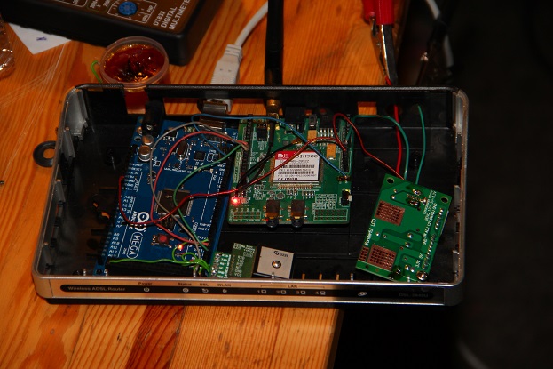
After installing the power converter and placing it in the case of a dead DSL modem, the system looks like this:
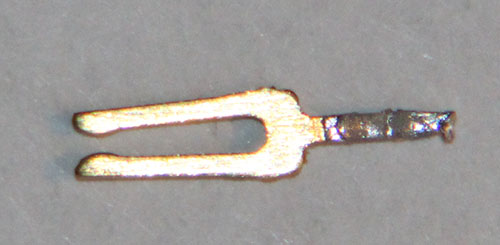
I soldered the wires, took out several contacts from the arduin's pads. Look like this:
I connected 12V in the car, drove around Moscow, got a track:
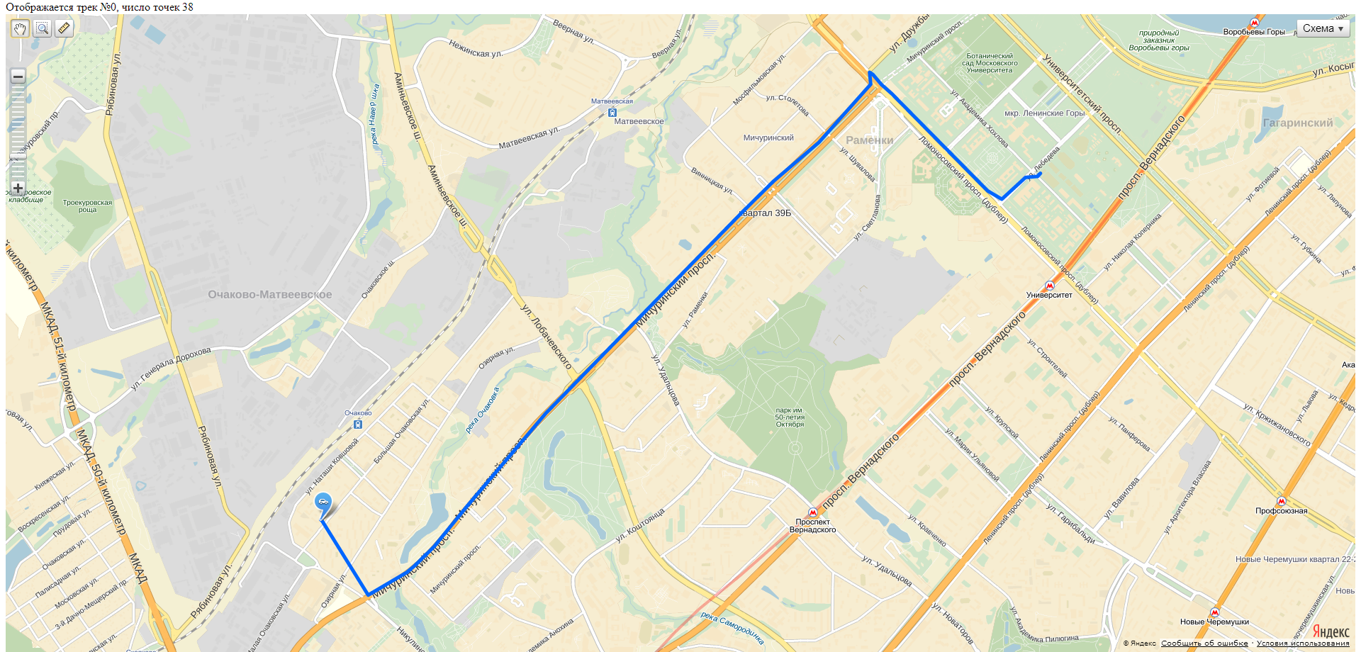
The track points are far enough apart. The reason is that sending data via GPRS takes a relatively long time, and at this time the coordinates are not read. This is a clear programming error. It is treated first, by sending immediately a bundle of coordinates with time, and secondly, by asynchronous work with the GPRS module.
The search time for satellites in the passenger seat of the car is a couple of minutes.
Creating a GPS tracker on arduino with your own hands is possible, although it is not a trivial task. The main question now is how to hide the device in the car so that it is not exposed to harmful factors (water, temperature), was not covered by metal (GPS and GPRS will be shielded) and was not particularly noticeable. While just lying in the cabin and connects to the cigarette lighter socket.
Well, and still need to correct the code for a smoother track, although the main task tracker and so does.
The published code can be used for any purposes permitted by law by any persons. The quality of the code is terrible, because it is still a test case. When I add to something more beautiful, update.
To compile the code for Arduino, you need to import the tinygps library.
UPD Code: GDrive
Sketch
The Arduino Mega 2560 (Arduino Uno) is used, the SIM900 is a GSM / GPRS module (to send information to the server), a SKM53 GPS receiver.
Everything was purchased on ebay.com, in the amount of about 1500 r (about 500r arduin, a little less - GSM module, a little more - GPS).
GPS receiver
First you need to deal with work with GPS. The selected module is one of the cheapest and simplest. Nevertheless, the manufacturer promises the presence of a battery for storing satellite data. According to the datasheet, the cold start should take 36 seconds, however, in my conditions (10th floor from the window sill, there are no buildings close) it took as much as 20 minutes. The next start, however, is already 2 minutes.
')
An important parameter of devices connected to the Arduin - power consumption. If you overload the Arduin converter, it may burn. For the receiver used, the maximum power consumption is 45mA @ 3.3v. Why in the specification to indicate the current strength on a voltage different from the required (5V) is a mystery to me. However, the 45 mA arduine converter will survive.
Connection
GPS is not controlled, although it has an RX pin. For what is unknown. The main thing you can do with this receiver is to read the NMEA data from the TX pin. Levels - 5V, just for Arduin, speed - 9600 baud. I connect the VIN to the VCC arduine, GND to GND, TX to RX of the corresponding serial. I read the data first manually, then using the TinyGPS library. Surprisingly, everything is read. After switching to Uno, I had to use SoftwareSerial, and then the problems started - some of the message characters were lost. This is not very critical, since TinyGPS cuts out invalid messages, but rather unpleasantly: you can forget about the frequency in 1 Hz.
A small note about SoftwareSerial: there are no hardware ports on Uno (except connected to USB Serial), so you have to use software. So, he can only receive data on the pin on which the board supports interrupts. In the case of Uno, these are 2 and 3. Moreover, only one such port can receive data at a time.
This is what a “test stand” looks like.
GSM receiver / transmitter
Now the more interesting part begins. GSM module - SIM900. It supports GSM and GPRS. Neither EDGE, nor even 3G, are supported. This is probably good for transferring coordinate data - there will be no delays and problems when switching between modes, plus GPRS is almost everywhere now. However, for some more complex applications this may not be enough.
Connection
The module is also controlled by a serial port, with the same level - 5V. And here we will need both RX and TX. The module is a shield, that is, it is installed on the arduin. And it is compatible with both mega and uno. The default speed is 115200.
We are going to Mega, and here we are waiting for the first unpleasant surprise: the TX pin of the module falls on the 7th pin of mega. At the 7m pin of the mega, interrupts are not available, which means you have to connect the 7th pin, say, to 6m, at which interruptions are possible. Thus, we will spend one pin of arduin for nothing. Well, for mega it's not very scary - still enough pins. But for Uno it is more difficult (remember, there are only 2 pins supporting interrupts - 2 and 3). As a solution to this problem, it is possible not to install the module on the arduin, but to connect it with wires. Then you can use Serial1.
After connecting, we are trying to “talk” with the module (do not forget to enable it). We select the port speed - 115200, while it’s good if all the built-in serial ports (4 on mega, 1 on uno) and all software work at the same speed. So you can achieve a more sustainable data transfer. Why - I do not know, although I guess.
So, we write a primitive code for transferring data between serial ports, send atz, in response to silence. What? And, case sensitive. ATZ, we get OK. Hurray, the module hears us. And do not call us for the sake of interest? ATD + 7499 ... The city telephone rings, the smoke comes from the arduine, the laptop is cut down. Arduino converter burned out. It was a bad idea to feed him with 19 volts, although it is written that he can work from 6 to 20V, recommend 7-12V. The datasheet on the GSM module does not say anywhere about the power consumption under load. Well, Mega is sent to the spare parts warehouse. With a sinking heart, I turn on the laptop, which received + 19V over a + 5V line from USB. It works, and even USB is not burned out. Thank you Lenovo for the protection.
After the converter burnout, I looked for the current consumed. So, the peak - 2A, typical - 0.5A. This is clearly not the strength of the Arduin converter. Need a separate power.
Programming
The module provides extensive data transfer capabilities. Starting from voice calls and SMS and ending, in fact, GPRS. And for the latter it is possible to perform an HTTP request using AT commands. We'll have to send a few, but it's worth it: you don't really want to form a request manually. There are a couple of nuances with the opening of the data transmission channel via GPRS - remember the classic AT + CGDCONT = 1, “IP”, “apn”? So, here the same thing is needed, but slightly more cunning.
To get the page at a specific URL, you need to send the following commands:
AT+SAPBR=1,1 // (Carrier) AT+SAPBR=3,1,"CONTYPE","GPRS" // - GPRS AT+SAPBR=3,1,"APN","internet" //APN, - internet AT+HTTPINIT // HTTP AT+HTTPPARA="CID",1 //Carrier ID . AT+HTTPPARA="URL","http://www.example.com/GpsTracking/record.php?Lat=%ld&Lng=%ld" // URL, sprintf AT+HTTPACTION=0 // GET // AT+HTTPTERM // HTTP As a result, if there is a connection, we will receive a response from the server. That is, in fact, we already know how to send coordinate data if the server accepts it via GET.
Nutrition
As I found out to feed the GSM module from the Arduino converter a bad idea, it was decided to buy a 12v-> 5v, 3A converter, on the same ebay. However, the module does not like power in 5V. We go to the hack: we connect 5V to the pin, from which comes 5V from the arduin. Then the built-in converter of the module (significantly more powerful than the converter of the Arduin, MIC 29302WU) makes 5V of what the module needs.
Server
The server wrote a primitive - storing coordinates and drawing on Yandex.cards. In the future, it is possible to add various features, including support for many users, the status of "armed / not armed," the state of the vehicle systems (ignition, headlights, etc.), it is even possible to control the vehicle systems. Of course, with the appropriate support for the tracker, smoothly turning into a full-fledged alarm.
Field trials
Here is the assembled device, without the case:
After installing the power converter and placing it in the case of a dead DSL modem, the system looks like this:
I soldered the wires, took out several contacts from the arduin's pads. Look like this:
I connected 12V in the car, drove around Moscow, got a track:
The track points are far enough apart. The reason is that sending data via GPRS takes a relatively long time, and at this time the coordinates are not read. This is a clear programming error. It is treated first, by sending immediately a bundle of coordinates with time, and secondly, by asynchronous work with the GPRS module.
The search time for satellites in the passenger seat of the car is a couple of minutes.
findings
Creating a GPS tracker on arduino with your own hands is possible, although it is not a trivial task. The main question now is how to hide the device in the car so that it is not exposed to harmful factors (water, temperature), was not covered by metal (GPS and GPRS will be shielded) and was not particularly noticeable. While just lying in the cabin and connects to the cigarette lighter socket.
Well, and still need to correct the code for a smoother track, although the main task tracker and so does.
Used devices
- Arduino Mega 2560 [compatible]
- Arduino Uno [compatible]
- GPS SkyLab SKM53
- SIM900 based GSM / GPRS Shield
- DC-DC 12v-> 5v 3A converter
Literature
- Of Arduino site (contains detailed information about boards and their programming)
- TinyGPS (download link in the middle of the page)
- GPS SKM53 Datasheet
- GSM / GPRS Shield description on SIM900
- SIM900 AT Commands
- Yandex.Cards documentation
Code
The published code can be used for any purposes permitted by law by any persons. The quality of the code is terrible, because it is still a test case. When I add to something more beautiful, update.
To compile the code for Arduino, you need to import the tinygps library.
UPD Code: GDrive
Sketch
Source: https://habr.com/ru/post/196150/
All Articles