Radiadic floor lamp or another "2 pennies" in the piggy bank of the "smart home"
After a series of posts about the DIY-dimmer of the “smart home” I decided to tell about my implementation of such a project.
The purpose of my post is to share experiences and suggest several directions for reflection.
On one of the evenings, a “floor lamp” that had been forgotten in a living room corner, which no one had turned on for a long time, “discovered” was found.
')
This is due to the fact that the light in the living room is controlled by a Logitech universal console and via the web. To make it possible, a small piece of hardware was made on the Arduino, which received IR commands from the console and “pressed the buttons” on the radio remote control from the ceiling light. In addition, this piece of hardware is equipped with the nRF24L01 + module and can receive commands from other modules, in particular, my LAN and GSM gateways, and transmit data about its state. But it is not about her in this post (wrote a little about it here ).
So, a “problem area” was discovered - an unradiated floor lamp .
After thinking about this topic, it was thought that a similar task (remote on-off) can even be very useful in at least two more places - the power of the router and the modem provider (implement a reboot "on power").
Thus, it turns out that the project is at least not “one-time” and can be replicated in the near and not so near future.
Said and done, I look at what is in the “bins of the motherland” (a box with radio parts) and discover:
I decided to abandon the quartz resonator in the circuit in favor of simplifying the circuit and the board.
MK will program via ISP using USBtinyISP programmer, which has also been waiting for its time.
Immediately thought about the power of the developed module.
To fence one more power supply unit to the power supply unit, which commutes the power of the floor lamp (or other device), somehow did not want to. Make a complete circuit with power right away - too. And then I came across charging for the iPhone (I found a place in Moscow where you can buy them for 100 rubles each and on that occasion I bought 5 pieces “in reserve”).
The right tool in hand and voila:
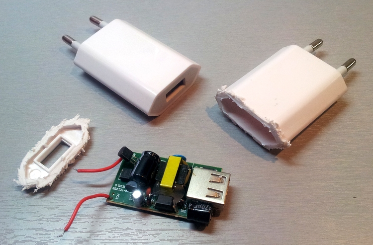
Wonderful shawl pulse BP with 5V output and current up to 1A - I use it.
The first prototype is implemented on a breadboard and proudly demonstrated to the wife at work.
The first reaction: "But you will not leave this structure in this form and make a body for it?"
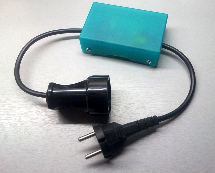
The case was "made" of the usual soap dish.
To the unit was "universal", equipped with a conventional electrical plug and the appropriate outlet. The socket, unfortunately, at that time found only one similar to that I used to make a garden extension cord (purchased at a hardware store). To put it mildly, both the plug and the socket are somewhat large.
In general, as usual - "I blinded him from what was":
It took a couple of hours to make a prototype.
Somewhere it took an hour to write and test a sketch and small dances with a tambourine to fill it with MK (not a single MK with firmware was damaged by incorrectly set fusions).
After several days of trial operation, the floor lamp has found a “second life”.
You can start replication.
Only this time, the iteration began with a search for a suitable case in which the main board and the power supply board fit. Additionally, I wanted to leave the charging function (USB-connector).
A suitable case was found in the near "Chip and Dip" (yes, expensive, but right away). The size of the case 63x44x31mm and its internal layout quite clearly gave the dimensions of the future mainboard.
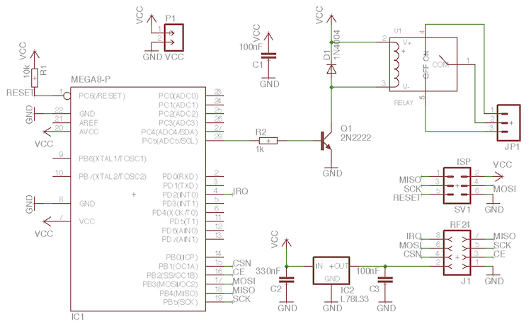
Scheme quickly threw in Eagle and spread the fee there.
upd : scheme:
At first I wanted to dwell on a one-sided board, but after several attempts at optimizing the wiring, I abandoned this idea and decided to LOCK the double-sided board using this method .
For me it was the first experience (once 100% successful, although not without flaw).
Thus, we got all the components of the future module:
The first "fitting" to the new building:

Later, between the boards, a rigid gasket was added, cut from an old plastic card to eliminate possible contact.
Additionally, a hole for the USB connector was arranged in the case, so that you could also charge something from this unit (there is a table next to the floor lamp on which the phones / tablets regularly “spend the night”).
Actually, the resulting device next to the prototype:
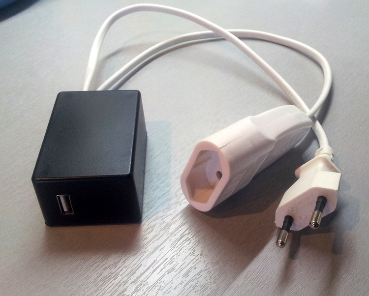
This time I took a more compact plug and socket (an extension cord from IKEA went to the “expense”). Unfortunately, they are only white; the black version would suit me more:
Everything is clear with the floor lamp, but when I began to “try on” this module to the router and modem, I realized that I did not think of some things and the following functions were added to the sketch:
At the moment, both modules (the prototype and the first in the “series”) are successfully working and solving their problems. A pair of boards and cases waiting in the wings ...
In my head, thoughts of circuit breakers wander into standard plug-in boxes (and the idea to disassemble one of the Chinese radio-controlled switches , in order to produce a small reverse engineering, so as not to step on any other rake or even “gut” it almost entirely and replace the insides with its own).
Having a sufficient set of such "switches", you can safely implement any automatic scenarios based on data from any wired or wireless "sensors", but about this some time next ...
The purpose of my post is to share experiences and suggest several directions for reflection.
For me, “smart home” is when there is some problem area in ordinary home life, some decision is made for it, which starts working without human participation and allows you to forget this problem area for at least a long time, and ideally forever.
On one of the evenings, a “floor lamp” that had been forgotten in a living room corner, which no one had turned on for a long time, “discovered” was found.
')
This is due to the fact that the light in the living room is controlled by a Logitech universal console and via the web. To make it possible, a small piece of hardware was made on the Arduino, which received IR commands from the console and “pressed the buttons” on the radio remote control from the ceiling light. In addition, this piece of hardware is equipped with the nRF24L01 + module and can receive commands from other modules, in particular, my LAN and GSM gateways, and transmit data about its state. But it is not about her in this post (wrote a little about it here ).
So, a “problem area” was discovered - an unradiated floor lamp .
After thinking about this topic, it was thought that a similar task (remote on-off) can even be very useful in at least two more places - the power of the router and the modem provider (implement a reboot "on power").
Later, the idea appeared to make our own switches (yes, for installation in standard podrozetniki and also managed through a radio channel), but so far they have not reached the point of implementation due to lack of time.
Thus, it turns out that the project is at least not “one-time” and can be replicated in the near and not so near future.
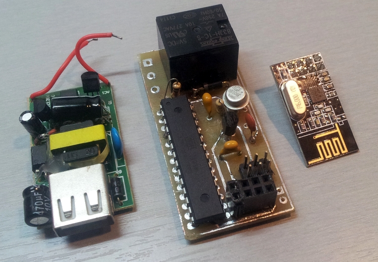
Said and done, I look at what is in the “bins of the motherland” (a box with radio parts) and discover:
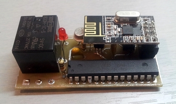
- prudently purchased relyushki with a voltage of 5V, which the “adults” 250V with their current up to 7A can switch to themselves,
- I wanted to use atmega168 as an MK, but it turned out that I purchased a couple of atmega8 in DIP packages for some of my future needs, but my hands haven’t reached them yet - it’s their turn,
- a pack of transistors KT306G (still from Soviet times).
I decided to abandon the quartz resonator in the circuit in favor of simplifying the circuit and the board.
MK will program via ISP using USBtinyISP programmer, which has also been waiting for its time.
Immediately thought about the power of the developed module.
To fence one more power supply unit to the power supply unit, which commutes the power of the floor lamp (or other device), somehow did not want to. Make a complete circuit with power right away - too. And then I came across charging for the iPhone (I found a place in Moscow where you can buy them for 100 rubles each and on that occasion I bought 5 pieces “in reserve”).
The right tool in hand and voila:
Wonderful shawl pulse BP with 5V output and current up to 1A - I use it.
The first prototype is implemented on a breadboard and proudly demonstrated to the wife at work.
The first reaction: "But you will not leave this structure in this form and make a body for it?"
The case was "made" of the usual soap dish.
To the unit was "universal", equipped with a conventional electrical plug and the appropriate outlet. The socket, unfortunately, at that time found only one similar to that I used to make a garden extension cord (purchased at a hardware store). To put it mildly, both the plug and the socket are somewhat large.
In general, as usual - "I blinded him from what was":
It took a couple of hours to make a prototype.
Somewhere it took an hour to write and test a sketch and small dances with a tambourine to fill it with MK (not a single MK with firmware was damaged by incorrectly set fusions).
After several days of trial operation, the floor lamp has found a “second life”.
You can start replication.
Only this time, the iteration began with a search for a suitable case in which the main board and the power supply board fit. Additionally, I wanted to leave the charging function (USB-connector).
A suitable case was found in the near "Chip and Dip" (yes, expensive, but right away). The size of the case 63x44x31mm and its internal layout quite clearly gave the dimensions of the future mainboard.
Scheme quickly threw in Eagle and spread the fee there.
If a scheme and fee is required - let us know in the comments - I will make an update to the article.
upd : scheme:
At first I wanted to dwell on a one-sided board, but after several attempts at optimizing the wiring, I abandoned this idea and decided to LOCK the double-sided board using this method .
For me it was the first experience (once 100% successful, although not without flaw).
The technology has been described many times, anyone can get acquainted with my personal “rake”.
The board pattern was printed on a Samsung SCX-3200 laser multifunction printer. I had to do it at a party and in a hurry, so I probably didn’t find all the right settings: maximum toner quantity and maximum quality - I found the first setting, but I didn’t get to the second one or the print quality of the device was insufficient for LUT. As a result, the pattern turned out to be only “tolerable” - at the edges of the image of the tracks there was a “fringe”, which was later also transferred to the resulting board.
Since this is the “first experience,” I decided to use this template and make a “test” fee.
To transfer the toner to the foil-clad glass fiber laminate, I used the substrate from children's stickers (it turns out, now they sell whole “sticker books” instead of old-fashioned “coloring books”). The material itself is a great fit, but due to the fact that the stickers are “cut down” on the press, the base has suffered (in the photo below you can see the characteristic “cuts” in the places of the former stickers):
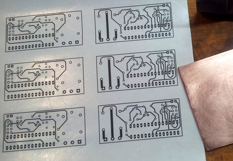
After a thorough “ironing” and subsequent “soaking”, the toner almost completely switched to the future board (the paper just peeled off the board, and the toner remained on the copper). But in the places of the “cuts” copper oxidized (elevated temperature and access of air) - this is clearly seen in the photo:

The board before etching was carefully examined under the lamp - the tracks did not have to be tinted.
Travil in a solution of ferric chloride, constantly controlling the process (recalling his children's crafts, when the board drew a cap-varnish).
The result turned out to be quite viable (on the tracks, in some places, the not completely washed out toner is visible):
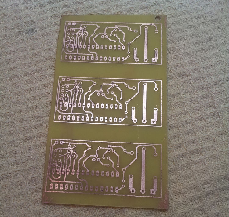
After a careful inspection of the boards on the light, it turned out another jamb pattern - insufficient toner density, which was particularly well noticeable on thick tracks. This defect looked like a mesh of very, very small etched holes, arranged in a strict geometric order.
The tracks were soldered with a soldering iron (325 degrees), I used ordinary glycerin as a flux - the resulting board completely satisfied me - no “sticky” and “cracks” (the “mesh” also dragged on).
The board was spread out in such a way that there was not a single “free” vias (i.e., all the transitions only through the lead elements). But a little miscalculated: several transitions were under the ISP connector and the connector under the radio module. When installing, I thought about how to get around this, and found a fairly simple solution: dissolve the stranded wire into thin strands and carefully solder the pieces of this strand on both sides in the holes where a transition was needed, while minimally occupying the space inside the hole. This made it possible to realize the transition and the holes were left free enough so that the corresponding connectors would normally fall into place and be unsoldered.
Oddly enough, even the use of not the best template, gave quite a suitable result.
Since this is the “first experience,” I decided to use this template and make a “test” fee.
Much later, he printed his templates on the HP1320n with the “correct” settings - the quality was incomparably higher and no unwanted artifacts were seen on the printout.
To transfer the toner to the foil-clad glass fiber laminate, I used the substrate from children's stickers (it turns out, now they sell whole “sticker books” instead of old-fashioned “coloring books”). The material itself is a great fit, but due to the fact that the stickers are “cut down” on the press, the base has suffered (in the photo below you can see the characteristic “cuts” in the places of the former stickers):
After a thorough “ironing” and subsequent “soaking”, the toner almost completely switched to the future board (the paper just peeled off the board, and the toner remained on the copper). But in the places of the “cuts” copper oxidized (elevated temperature and access of air) - this is clearly seen in the photo:
The board before etching was carefully examined under the lamp - the tracks did not have to be tinted.
Travil in a solution of ferric chloride, constantly controlling the process (recalling his children's crafts, when the board drew a cap-varnish).
The result turned out to be quite viable (on the tracks, in some places, the not completely washed out toner is visible):
After a careful inspection of the boards on the light, it turned out another jamb pattern - insufficient toner density, which was particularly well noticeable on thick tracks. This defect looked like a mesh of very, very small etched holes, arranged in a strict geometric order.
The tracks were soldered with a soldering iron (325 degrees), I used ordinary glycerin as a flux - the resulting board completely satisfied me - no “sticky” and “cracks” (the “mesh” also dragged on).
The board was spread out in such a way that there was not a single “free” vias (i.e., all the transitions only through the lead elements). But a little miscalculated: several transitions were under the ISP connector and the connector under the radio module. When installing, I thought about how to get around this, and found a fairly simple solution: dissolve the stranded wire into thin strands and carefully solder the pieces of this strand on both sides in the holes where a transition was needed, while minimally occupying the space inside the hole. This made it possible to realize the transition and the holes were left free enough so that the corresponding connectors would normally fall into place and be unsoldered.
Oddly enough, even the use of not the best template, gave quite a suitable result.
Thus, we got all the components of the future module:
The first "fitting" to the new building:
Later, between the boards, a rigid gasket was added, cut from an old plastic card to eliminate possible contact.
Additionally, a hole for the USB connector was arranged in the case, so that you could also charge something from this unit (there is a table next to the floor lamp on which the phones / tablets regularly “spend the night”).
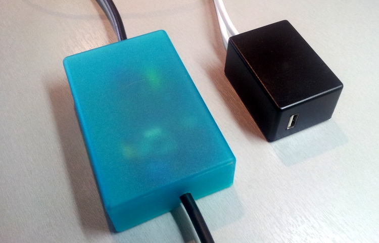
Actually, the resulting device next to the prototype:
This time I took a more compact plug and socket (an extension cord from IKEA went to the “expense”). Unfortunately, they are only white; the black version would suit me more:
Everything is clear with the floor lamp, but when I began to “try on” this module to the router and modem, I realized that I did not think of some things and the following functions were added to the sketch:
- save to EEPROM current state (on / off)
- restore the current state after a reset (for example, when power is turned off).
- temporary operation (permanent switching or temporary). For example, for a router and a modem, you do not need to give two commands - “turn off” and then “turn on”, and give one command “turn off for XX seconds”
- the ability to remotely change all the parameters of a block through a radio channel and save these parameters in the EEPROM (not to make unique firmware for a specific device, but to be able to configure a specific block for a specific task)
- the ability to remotely read all the current parameters of the block (both state and "settings")
- “Guard dog” (it would be foolish to leave the router or modem without power due to the module “hanging up” and denying access to home systems from the outside).
At the moment, both modules (the prototype and the first in the “series”) are successfully working and solving their problems. A pair of boards and cases waiting in the wings ...
In my head, thoughts of circuit breakers wander into standard plug-in boxes (and the idea to disassemble one of the Chinese radio-controlled switches , in order to produce a small reverse engineering, so as not to step on any other rake or even “gut” it almost entirely and replace the insides with its own).
Having a sufficient set of such "switches", you can safely implement any automatic scenarios based on data from any wired or wireless "sensors", but about this some time next ...
Source: https://habr.com/ru/post/195884/
All Articles