Automatic lap and time counting system for RC cars
Not so long ago, I collected my AMB counterpart, also known as MyLaps. For those who do not know - this is a very sophisticated system for counting the circles of radio-controlled models, kartings, and even motorsport. The cost of the finished kit from MyLaps just space. My task was to create either a clone or the most compatible one. What I got at the moment.
Not so long ago, I was actively engaged in automotive sports. Periodically I began to go to more or less major competitions in the nearest cities (Vladimir, Zarechny, I want to visit Tyumen in the summer of course), even moved to a more normal model and got pontovye devices to adjust the chassis. A few photos, I apologize for the quality:
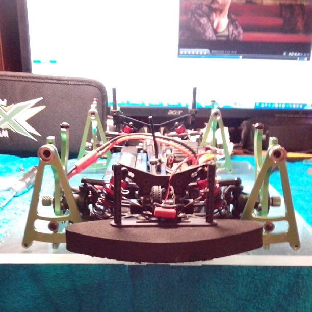
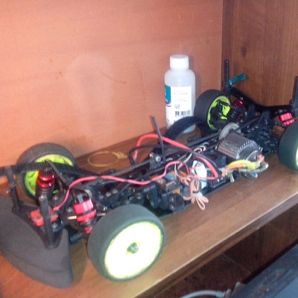

In short - this sport has tightened very much.
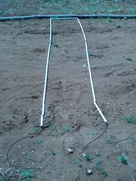
Immediately began to think about how to make your own system of counting circles (later in the text of her call "notch"). The first attempts were implemented on the basis of RFID tags, which I converted into active ones. The idea is so-so. To cover the entire width of the track and eliminate collisions, several decoders and several loops were required:

The label itself:

Increased the carrier frequency from 125 to 500kHz, but there was no particular result.
After active google found a post on rctech.net . Howard also started doing something. I even laid out the detector and amplifier circuits, which I used.
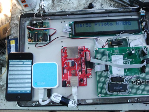
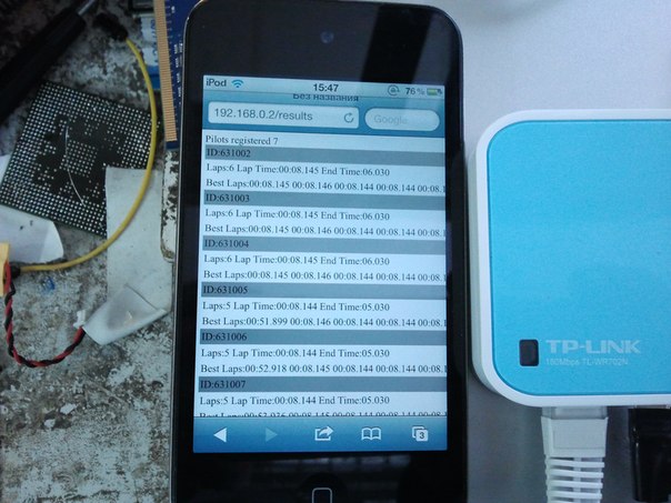
Already here I began to make a decoder that works with original AMB transponders and self-made ones. And he even made his WiFi-based interface, but the project is still rotten:
')
Here is a black decoder box:

Inside this shawl:

Loop enhancer:

Detection loop itself:
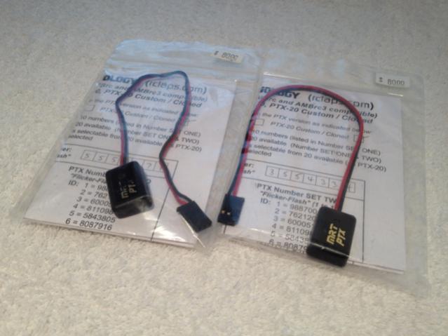
And transponders:

Today I want to consider in more detail how the transponder works and how it manages so quickly to transmit 13 byte identifiers per 100µs.
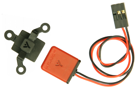
This is what the original transponders look like:
AMBrc dp

MRT (AMB clones)
AMB RC4 Hybrid
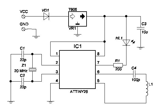
This is how Howard transponders look like:

And the scheme:
More detailed topic about them on rctech.net . If interested - please read.
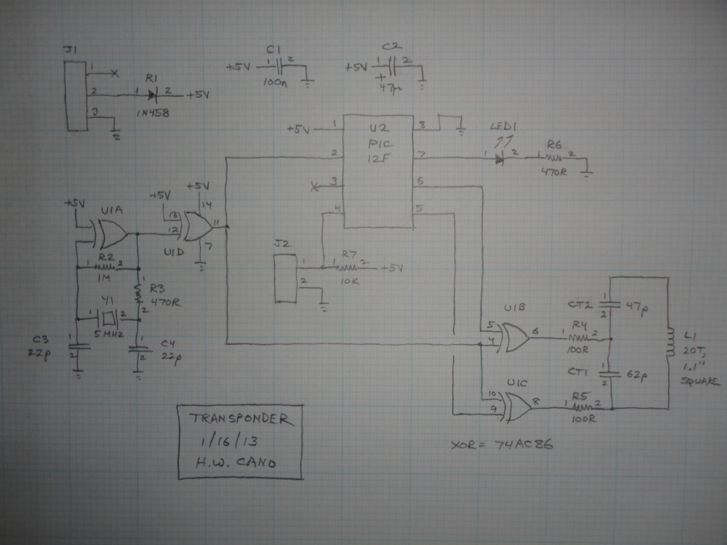
I'll start with the scheme of their handicrafts:
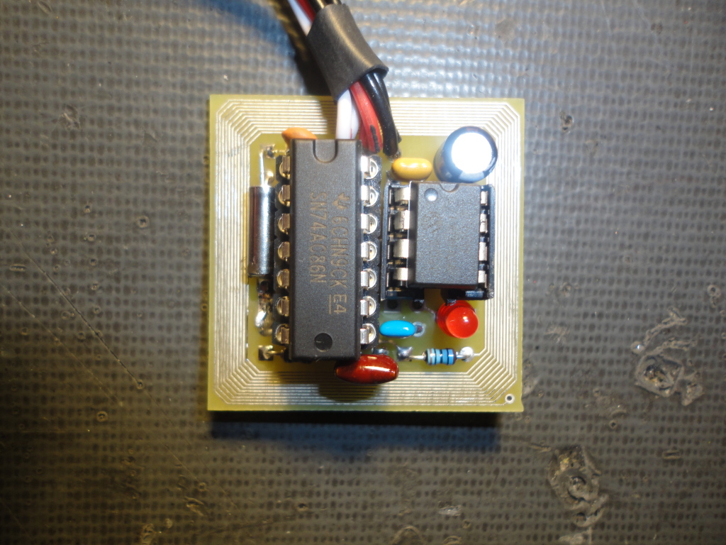
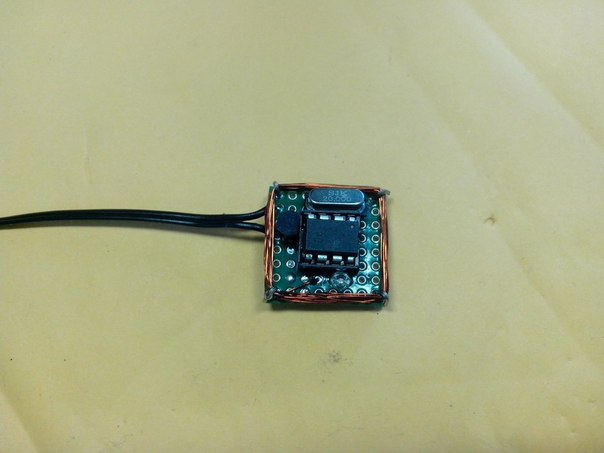
and photos:

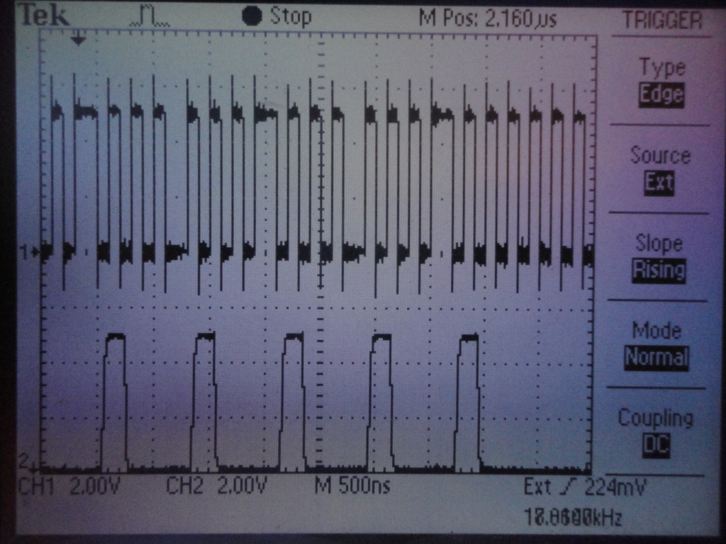
The first thing that catches your eye is a coil around the board. This can be called an antenna. The diagram is L1. For resonance, a 100 pF capacitor is connected to it. I remind you that the carrier in the original AMB transponders is 5 MHz. The data transfer method is BPSK, i.e. the phase shift. Perhaps I'll show a couple of waveforms for clarity:


and some Howard waveforms:

ps on the latest Howard waveforms testing a phase shift detector, still analog, apparently.
Regarding the power supply, you can use a 200 ohm resistor and a 5.1V zener diode, for 5V LDO stabilizers are expensive.
We use Attiny25 as a controller for several reasons:
1. Built-in 64 MHz generator, which is not useful
2. Programming for debugWire
3. Powered by 20 MHz.
4. There is an interesting mode of PWM, which is useful to me.
I'll start with an interesting PWM mode:
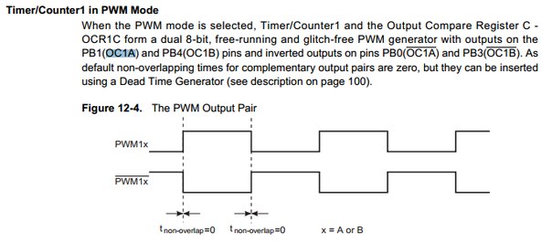
We can make 5 and 6 leg work in antiphase, and this removes some of the external unnecessary strapping.
Timer initialization:
This will allow our timer to operate at 5 MHz and generate rectangular pulses at the PWM outputs.
Each bit of information is transmitted once every 800 ns, which is 16 machine cycles at 20 MHz. To implement such a fast transfer, I had to write each bit to a separate memory byte before sending the code. I did not invent another easier way.
Of the 13 transmitted bytes, the first 2 bytes are always 0x79 0x16. Howard calls them the preamble. These bytes will come in handy later. For these bytes, the FPGA issues a VALID signal, which indicates to the scooter that a label has passed over the loop.
So, before transferring the remaining 11 bytes, they need to be scattered in 88 bytes of RAM:
I didn’t bother with the transfer of the first two bytes and did so:
But PhaseChange and NoPhaseChange themselves. To change the phase you need to turn off and turn on the timer for 4 cycles. Each entry in the timer register takes two ticks. Well, to do nothing you just have to wait for 4 bars.
So the transfer of the first two bytes is pretty dumb.
And actually transfer the remaining 11 bytes:
Here one machine cycle takes if else.
The signal after the BPSK detector looks like this:

By the way, the time between transmissions of each code varies randomly from 1ms to 2ms
A logical question arises, what do we need to transmit. I will write about my protocol later, but for now I’ll give the codes of those original transponders that I have:
I could not find the relationship between the transmitted code and the transponder number. My transponder clones with the original AMBrc3 serif work like this: see one time, then stop. I suspect that the problem still lies in the additionally transmitted information:
It is badly seen due to interference, but every three parcels with an identifier (E12AD9E1EED94E07830F40), another package is sent with additional information (D417A27CD8B9BA4E40CC40).
Everything is complicated by the fact that I can only check transponders at competitions. Seen the cost of the order of 4,000 euros no one will play me.
Everything is complicated by the fact that I can only check transponders at competitions. Seen the cost of the order of 4,000 euros no one will play me.
For those who want to see how this works in Proteus, please come here.

I want to say that in the next article I will tell you a little about the BPSK detector (half of the circuit is taken from rctech.net and crammed into the FPGA), but I’ll tell you more about the software part of the decoder. I will tell about AMB20 and AMBRc protocols working on Rs-232, about how I implemented compatibility with original AMB transponders
Prehistory
Not so long ago, I was actively engaged in automotive sports. Periodically I began to go to more or less major competitions in the nearest cities (Vladimir, Zarechny, I want to visit Tyumen in the summer of course), even moved to a more normal model and got pontovye devices to adjust the chassis. A few photos, I apologize for the quality:
In short - this sport has tightened very much.
Immediately began to think about how to make your own system of counting circles (later in the text of her call "notch"). The first attempts were implemented on the basis of RFID tags, which I converted into active ones. The idea is so-so. To cover the entire width of the track and eliminate collisions, several decoders and several loops were required:
The label itself:
Increased the carrier frequency from 125 to 500kHz, but there was no particular result.
After active google found a post on rctech.net . Howard also started doing something. I even laid out the detector and amplifier circuits, which I used.
Already here I began to make a decoder that works with original AMB transponders and self-made ones. And he even made his WiFi-based interface, but the project is still rotten:
')
What I have at the moment
Here is a black decoder box:
Inside this shawl:
Loop enhancer:
Detection loop itself:
And transponders:
Today I want to consider in more detail how the transponder works and how it manages so quickly to transmit 13 byte identifiers per 100µs.
Transponder
This is what the original transponders look like:
AMBrc dp
MRT (AMB clones)
AMB RC4 Hybrid
This is how Howard transponders look like:
And the scheme:
More detailed topic about them on rctech.net . If interested - please read.
I'll start with the scheme of their handicrafts:
and photos:
The first thing that catches your eye is a coil around the board. This can be called an antenna. The diagram is L1. For resonance, a 100 pF capacitor is connected to it. I remind you that the carrier in the original AMB transponders is 5 MHz. The data transfer method is BPSK, i.e. the phase shift. Perhaps I'll show a couple of waveforms for clarity:
and some Howard waveforms:
ps on the latest Howard waveforms testing a phase shift detector, still analog, apparently.
Regarding the power supply, you can use a 200 ohm resistor and a 5.1V zener diode, for 5V LDO stabilizers are expensive.
We use Attiny25 as a controller for several reasons:
1. Built-in 64 MHz generator, which is not useful
2. Programming for debugWire
3. Powered by 20 MHz.
4. There is an interesting mode of PWM, which is useful to me.
I'll start with an interesting PWM mode:
We can make 5 and 6 leg work in antiphase, and this removes some of the external unnecessary strapping.
Timer initialization:
// Timer/Counter 1 initialization // Clock source: System Clock // Clock value: 20000,000 kHz // Mode: PWMA top=OCR1C // OC1A output: Non-Inv., /OC1A connected // OC1B output: Disconnected // Timer1 Overflow Interrupt: Off // Compare A Match Interrupt: Off // Compare B Match Interrupt: Off PLLCSR=0x00; TCCR1=0x51; GTCCR=0x00; TCNT1=0x00; OCR1A=2; OCR1B=0x00; OCR1C=3; This will allow our timer to operate at 5 MHz and generate rectangular pulses at the PWM outputs.
Each bit of information is transmitted once every 800 ns, which is 16 machine cycles at 20 MHz. To implement such a fast transfer, I had to write each bit to a separate memory byte before sending the code. I did not invent another easier way.
Of the 13 transmitted bytes, the first 2 bytes are always 0x79 0x16. Howard calls them the preamble. These bytes will come in handy later. For these bytes, the FPGA issues a VALID signal, which indicates to the scooter that a label has passed over the loop.
So, before transferring the remaining 11 bytes, they need to be scattered in 88 bytes of RAM:
do { if (RFID_Buffer_ee[RFIDBufferPtr]&mask) { buffer[RFIDBit_Count]=1; } else { buffer[RFIDBit_Count]=0; } mask>>=1; if (!mask) { mask=0x80; RFIDBufferPtr++; } RFIDBit_Count++; } while (RFIDBit_Count<TransBuffSize); I didn’t bother with the transfer of the first two bytes and did so:
// TCCR1=0x51; // 8 delay_us(8); //transmit 0x79 0x16 NoPhaseChange NOP PhaseChange NOP PhaseChange NOP PhaseChange NOP PhaseChange NOP NoPhaseChange NOP NoPhaseChange NOP PhaseChange NOP NoPhaseChange NOP NoPhaseChange NOP NoPhaseChange NOP PhaseChange NOP NoPhaseChange NOP PhaseChange NOP PhaseChange NOP NoPhaseChange #asm("nop"); #asm("nop"); But PhaseChange and NoPhaseChange themselves. To change the phase you need to turn off and turn on the timer for 4 cycles. Each entry in the timer register takes two ticks. Well, to do nothing you just have to wait for 4 bars.
#define PhaseChange TCCR1=0x50; TCCR1=0x51; #define NoPhaseChange #asm("nop"); #asm("nop"); #asm("nop"); #asm("nop"); #define NOP #asm("nop"); #asm("nop"); #asm("nop"); #asm("nop"); #asm("nop"); #asm("nop"); #asm("nop"); #asm("nop"); #asm("nop"); #asm("nop"); #asm("nop"); #asm("nop"); So the transfer of the first two bytes is pretty dumb.
And actually transfer the remaining 11 bytes:
for (i=0;i<TransBuffSize;i++) { if (!buffer[i]) { #asm("nop"); #asm("nop"); #asm("nop");} else { TCCR1=0x50; TCCR1=0x51; }; } Here one machine cycle takes if else.
The signal after the BPSK detector looks like this:
By the way, the time between transmissions of each code varies randomly from 1ms to 2ms
A logical question arises, what do we need to transmit. I will write about my protocol later, but for now I’ll give the codes of those original transponders that I have:
//flash char RFID_Buffer_ee[BuffSize]={0xEF,0xD4,0xFE,0xF6,0xE1,0xD1,0x22,0xCD,0xCC,0x3C,0}; //9887001: //flash char RFID_Buffer_ee[BuffSize]={0x3B,0x21,0xC7,0x1F,0xF7,0xFE,0x3E,0xFE,0xC3,0x3F,0}; //9577130: flash char RFID_Buffer_ee[BuffSize]={0x0D,0xAE,0xAD,0xB2,0x49,0x89,0xB9,0x64,0xB3,0x33,0x48}; //8087916: //flash char RFID_Buffer_ee[BuffSize]={0x00,0xEF,0x35,0xEF,0x0E,0x26,0x0A,0xD8,0x3F,0xCF,0x48}; //8110984: //flash char RFID_Buffer_ee[BuffSize]={0xE1,0x2A,0xD9,0xE1,0xEE,0xD9,0x4E,0x07,0x83,0x0F,0x40}; //5495805: //flash char RFID_Buffer_ee[BuffSize]={0x35,0xD1,0x1E,0x21,0x2A,0x10,0x5D,0xd0,0x7F,0xCF,0x40}; //3472238: //flash char RFID_Buffer_ee[BuffSize]={0xDA,0xE4,0x2B,0x24,0x27,0xEF,0x87,0x31,0x4F,0x33,0x00}; //8959711: //flash char RFID_Buffer_ee[BuffSize]={0xD4,0x14,0xC7,0xCB,0xDF,0xD6,0x9A,0x17,0xBF,0xF0,0x40}; //8361115 //flash char RFID_Buffer_ee[BuffSize]={0xDA,0x0B,0x2B,0x14,0xFC,0xC7,0x2C,0xC2,0xF3,0x03,0x04}; //8718039: I could not find the relationship between the transmitted code and the transponder number. My transponder clones with the original AMBrc3 serif work like this: see one time, then stop. I suspect that the problem still lies in the additionally transmitted information:
EC84418105A6B5BD70CF0000 E12AD9E1EED94E07830F4001 E12AD9E7EED94E07C30F4002 E12AD9E1EED94E07830F4002 38A8F9C1ECA67A7E4FCC4002 E12AD9E1EED94E07830F4002 E12AD9E1EED9CE07830F4000 E12BDBE1EED94E07830F4000 E12AD9E1EED94E07830F4000 E12AD9E1EED94E07830F4001 E27B5E0BC356B9B98CC24001 E12BD9E1EED94E07830F4001 F12AD9E1EED94E07830F4000 E12AD9E1EED94E07830F4002 E12AD9E1EED94E07830F4002 E242145FC145858D4CCF0023 E12AD9E1EED94E07830F4000 E12AD9E1EED94E07830F4004 D417A27CD8B9BA4E40CC4002 E12AD9E1EED94E07830F4002 E12AD9E1EED94E07830F4023 E12AD9E1EED94E07830F4000 E12AD9E1EED94E07830F4000 E12AD9E1EED94E07830F4000 E12AD9E1EED94E07830F4000 E12BD9E1EED94E07830F4001 E12AD9E1EED94E07830F4002 E12AD9E1EED94E07830F4002 E12AD9E1EED94E07830F4000 3B14155CCA79B54D73000002 E12AD9E1EED94E07830F4002 E243145FC145858D4CCF0000 E12AD9E1EED94E07830F4000 E12A58E1EED94E07830F4002 E12AD9E1EED94E07830FC000 It is badly seen due to interference, but every three parcels with an identifier (E12AD9E1EED94E07830F40), another package is sent with additional information (D417A27CD8B9BA4E40CC40).
Everything is complicated by the fact that I can only check transponders at competitions. Seen the cost of the order of 4,000 euros no one will play me.
Everything is complicated by the fact that I can only check transponders at competitions. Seen the cost of the order of 4,000 euros no one will play me.
Files to emulate
For those who want to see how this works in Proteus, please come here.
Instead of conclusion
I want to say that in the next article I will tell you a little about the BPSK detector (half of the circuit is taken from rctech.net and crammed into the FPGA), but I’ll tell you more about the software part of the decoder. I will tell about AMB20 and AMBRc protocols working on Rs-232, about how I implemented compatibility with original AMB transponders
Source: https://habr.com/ru/post/195804/
All Articles