Welding of optical fibers. Part 2: welding machines and cleavers, mechanical and welded splicing, measuring and laying fibers
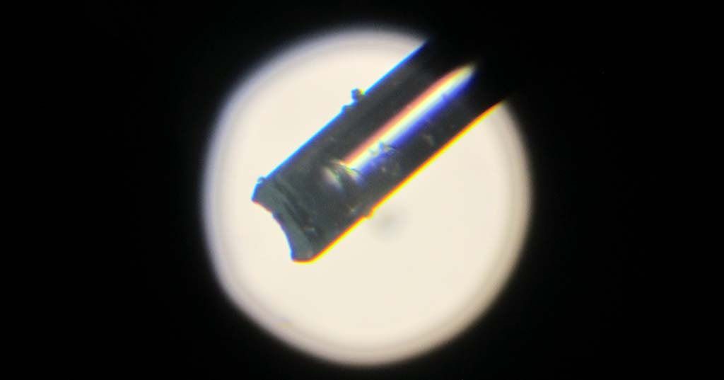
Broken optical fiber under the microscope
Hello, readers Habra!
In this second part of my story, I continue to describe the wisdom of working with fiber. I will, to the best of my experience and knowledge, acquaint you with welding machines for optics, tell you about cleavers, and touch upon the mechanical method of splicing fibers. And finally, there will be a description of the process of welding with video, the process of laying fibers and an overview of the results. In the end - a small bonus: the animations I made from a series of photographs of fibers under a microscope.
In the first part, I talked about cables and their cutting, optical tools, couplings and crosses, connectors and adapters.
')
Part 1 here
Part 3 here
Caution: a lot of text and traffic!
Welders

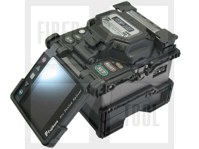
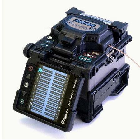
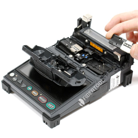
The latest Fujukura FSM-80S with an open lid and laid fibers. Fibertool
What is the welding machine under the lid
The arc-fusion splicer is one of the most expensive and complex (along with the OTDR) tools of the solder. This is a smart device that takes over the whole process of mixing (alignment) and fiber welding, the solder can only prepare them and lay them in the machine, and then pull them out, push the shrink sleeve KDZS and lay them in the oven. In short, the principle of operation of any modern welding machine is as follows:
1) Peeled, chopped fibers with a pre-worn KDZS protective sleeve are laid by the splicer into the device, being fixed with clamps.
2) The device itself (or by pressing a button) begins to reduce them, until it sees into the optical system, consisting of microscopic cameras and mirrors on the inner surface of the lid.
3) When both fibers are in the field of view of the cameras, the device gives a short, weak arc that “blows” micro fibers from the fibers, which usually remain despite any rubbing. It is believed that this short arc also slightly "melts" the fibers, preparing them for welding. If the fibers were flammable and undisturbed dirt (for example, hydrophobic or fat from the fingers), then this arc will only “bake” this dirt, so much so that no rubbing will help, only to redo the chips.
4) If the fibers are clean and the chips are good, he begins to reduce them with precision motors in three coordinates - first roughly, then for sure. If there is no order with the fibers, it tells us about it (writes on the screen and gives a signal with a squeak) and refuses to continue cooking.
5) When the fibers are flattened and moved very close to each other, somewhere for a second or two the main powerful arc is turned on, in which the fibers are heated, and in a heated form they are even slightly removed from each other in order to solder. After switching off the arc, the welding place cools down in a split second.
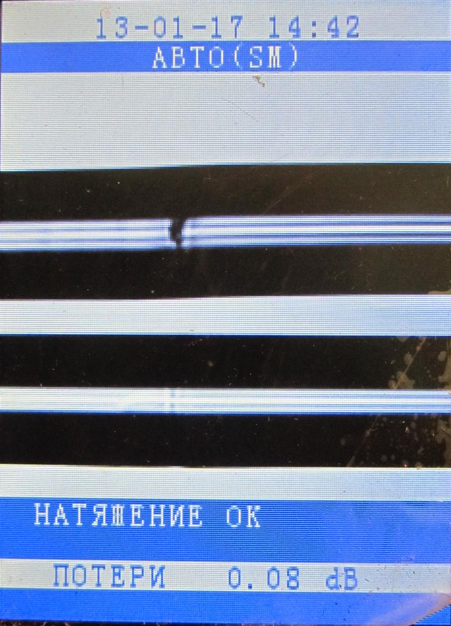
6) The device assesses from the picture whether there is no shoal (good welding is almost invisible), and also tries to approximately determine the attenuation on the resulting welding. Welding information (date, time, attenuation) is stored in memory, the non-resettable welding counter is increased by one.
7) The device with the dosed effort tries to dissolve the welded fibers back, if at the same time the welding is not torn - the strength test is passed. Many turn it off as unnecessary, there are even rumors that it can spoil the still cold welding.
8) The welded fiber gently pulls the welder, pulls the KDZS sleeve and puts it in the stove, where the KDZS shrinks, protecting the welding spot from impacts.
9) When the stove timer is out, the fiber from the hot KDZS is reached and the KDZS is put on a special shelf for cooling. If you put it on the table, the hot plastic will stick. It is impossible to push hot in a cassette in a cassette - it is easy to break the fiber under a soft plastic.
About the internal device, hardware and software parts, I, unfortunately, can not tell anything: I never had to either disassemble the welder or connect to a computer. I can only bow to electronics engineers, mechanics and optics who have created such a complex and precise device, and programmers who have written algorithms for working with the image of fibers.
The situation on the market today is this: the best welding machines are made by the Japanese (Fujikura, Sumitomo), the Chinese are on their heels (Jilong and others). It so happened that in Russia Fujikurs are more common than Sumit and Fitel (my subjective opinion).
The price of a modern welding machine, which can be used to solder responsible trunk lines, is rather big: it starts from 120-130 thousand rubles for Chinese (for a set - kit), and a good Japanese costs about 300-350 thousand rubles for a set. The “whale” set usually includes the welding machine itself, a case, a power supply unit, a cleaver, a fiber stripper, sometimes an additional battery, a shelf for folding and cooling seated fibers, tweezers / brushes / wires for cleaning, a strap for carrying the case, cables for connecting to the computer, CD with software and so on. Of the papers, there is usually instruction, the output test results and the declaration of conformity.
Welding machines can be roughly classified by purpose. I do not pretend to a reliable and comprehensive classification, but I will try.
1) For high-quality welding of single fibers. Such devices make alignment (mutual alignment) of the fibers to the light and the shell and the core, focusing on the picture from two cameras with microscopes at an angle of 90 degrees (PAS method - Profile Alignment System). This method is preferable to the outdated method of alignment of only one shell - because the fiber can be eccentric, slightly oval or with some axial displacement of the central 9-micron core. Servomotors in such devices can usually move the fibers "to each other - from each other", "down-up", "forward-backward", in addition, the microscopes on the cameras can change the focus for precise focusing. Modern welders are not able to rotate the fiber along the longitudinal axis or tilt at some angle to compensate for the deviation of the cleavage angle from the norm.
These are expensive, but high-quality and probably the most common devices, due to their versatility and quality. They are able to make an approximate estimate of the attenuation value in welding, calculating it using a clever algorithm from the welding image on the screen. Many models are able to weld fibers specifically with an offset, so that the welding is achieved with a given attenuation, when you need to get an attenuator. Examples are the entire Japanese Fujikura device from FSM-30S to FSM-80S, Sumitomo Type-39 (and friend), Furukawa Fitel S178A, with some stretch - Chinese Jilong KL-260C, KL-280, KL-300 / 300T and some other chinese
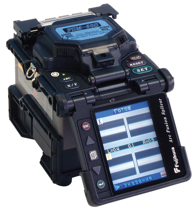
Fujikura FSM-60S
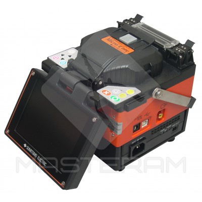
Sumitomo Type-39 Masteram
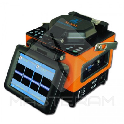
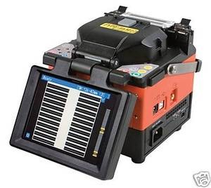
Jilong KL-300T
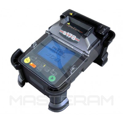
Furukawa-Fitel-S178A
2) The option is “cheaper” for welding less critical and hot lines , where welding is not pursued in attenuation. Such a welder reduces the fibers not at the core, looking at the image from the cameras, but simply moving along two particularly smooth V-shaped grooves, that is, many servomotors are not there. The camera and screen are only for operator control and an approximate assessment of losses. It is understood that the user will often solder multimode. It is clear that the accuracy of information and the quality of welding will be statistically worse, since the slightest speck of dust, the imperfection and lack of focus of the optical fibers themselves or a micro scratch on the groove sharply worsens the coaxiality of the cores in the fibers and, accordingly, the quality of welding. The price is lower than that of the “professional” Japanese, but higher or comparable with the “professional” Chinese. Therefore, I personally do not see the point of taking such a device. Example - Fujikura FSM-18S, Fujikura FSM-17S, possibly - Sumitomo Type-46.
Fujikura FSM-18S. Looks like the sixties. Fibertool
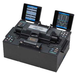
3) Welding machines for group welding of ribbon (ribbon) fibers. In Russia, there are almost none, as there are no corresponding cables, and other equipment (appropriate cleavers, thermostatrippers). The cable of this standard inside the cross-section is rectangular, and there are tapes made up of several (usually up to 12) fibers.
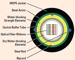
Ribbon Cable
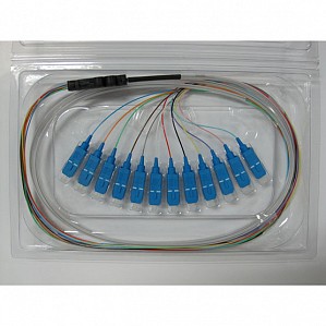
Ready set of pig-tails for cross-country, combined into a tape. One welding - and 12 ports cross welded. Great, right?
Such a welding machine cooks all the tape at once, saving time. For a long time, Fujikura in Russia pretended that these devices did not exist at all. I never saw such welding machines live. I don’t know exactly the principles of stripping, mixing and welding, and I can’t say anything about them. I also cannot say for sure if they can cook single fibers as simple welding machines. I see no reason to buy in Russia.
Fujikura FSM-60R
Sumitomo Type-66 Ribbon
4) Other second-tier devices for welding FTTx networks , for example, Sumitomo TYPE-25 and TYPE-25e. Border with group number 2 is difficult to hold. The design is less advanced and the quality of welding is not as high as that of the “trunk” devices, the battery is weaker, but the dimensions and price are lower. Here, for not very high quality, can be attributed cheap Chinese devices, such as DVP-730, Jilong KL-260C and others.
Fujukura FSM-12S
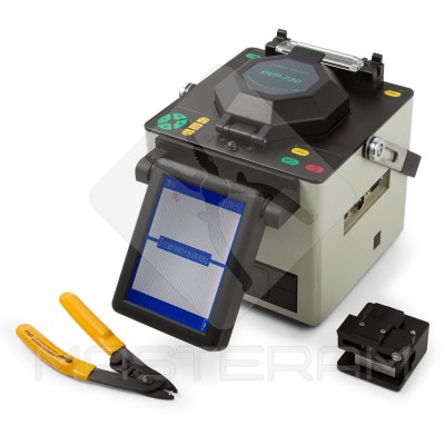
DVP-730 with a cleaver and stripper
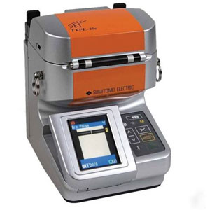
Sumitomo Type-25e
5) Special and laboratory welding machines for welding special fibers, for example, fibers with polarization preservation (Fujikura FSM-100M, FSM-100P, FSM-45F). Such devices are very expensive, have a bunch of flexible settings, require special clearing systems. How do you, for example, have the opportunity to make chips at an angle of 45 degrees and so cook?
Fujikura FSM-100P

Fujikura FSM-45F
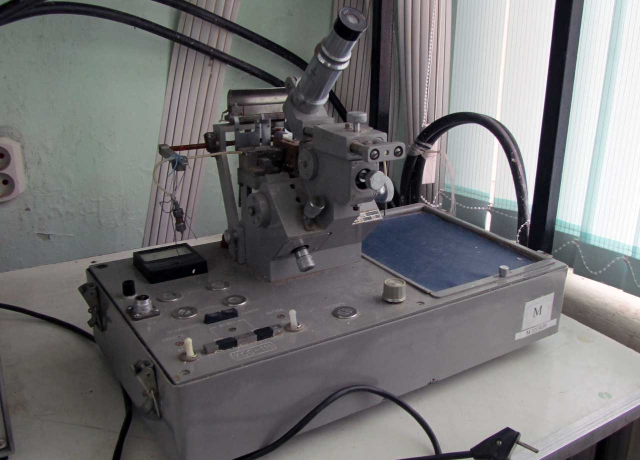
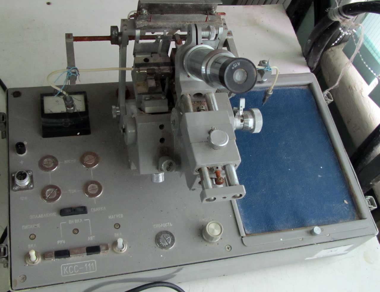
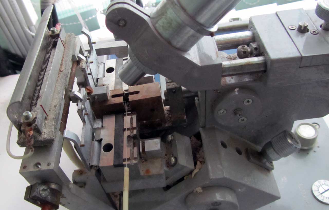
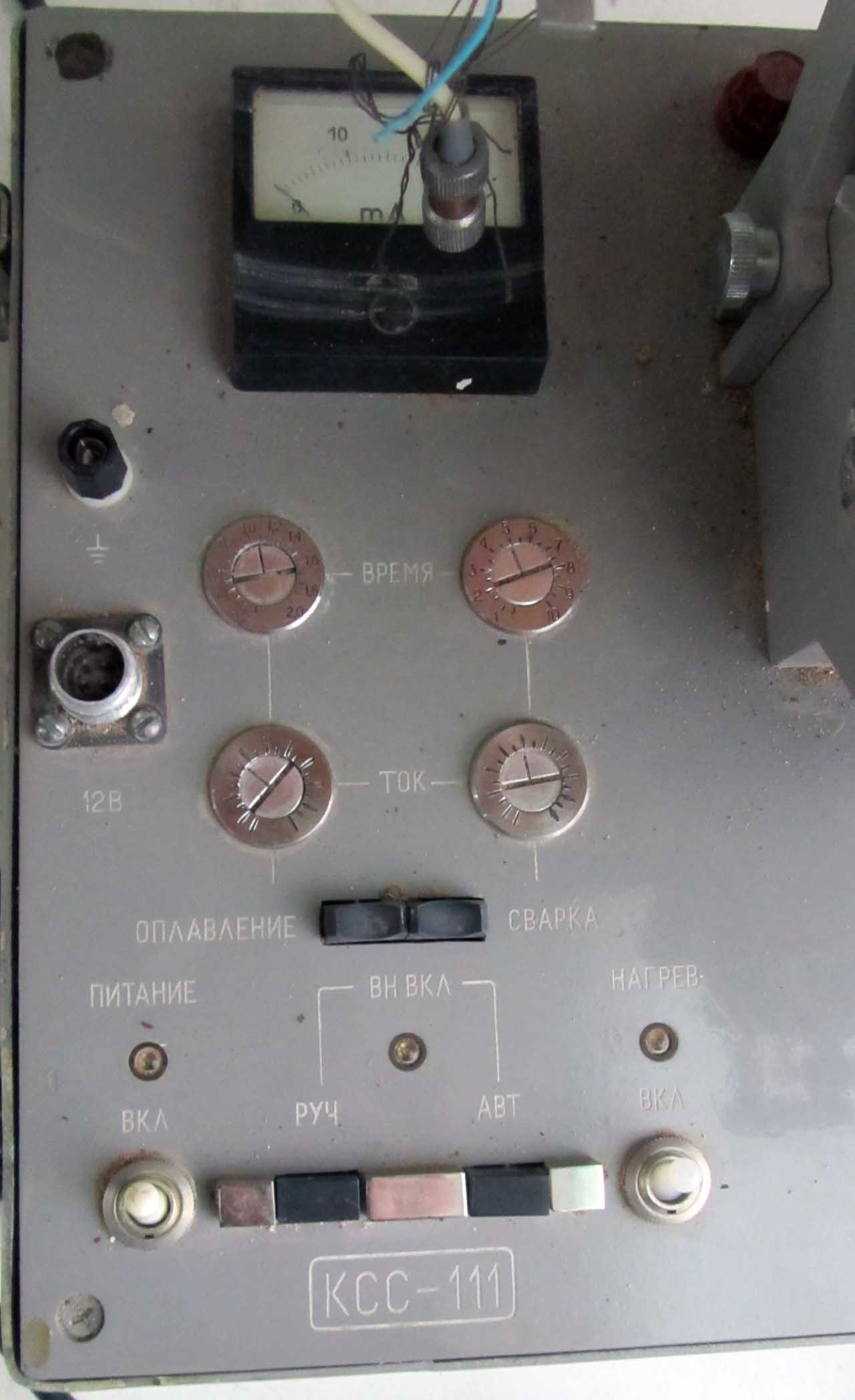
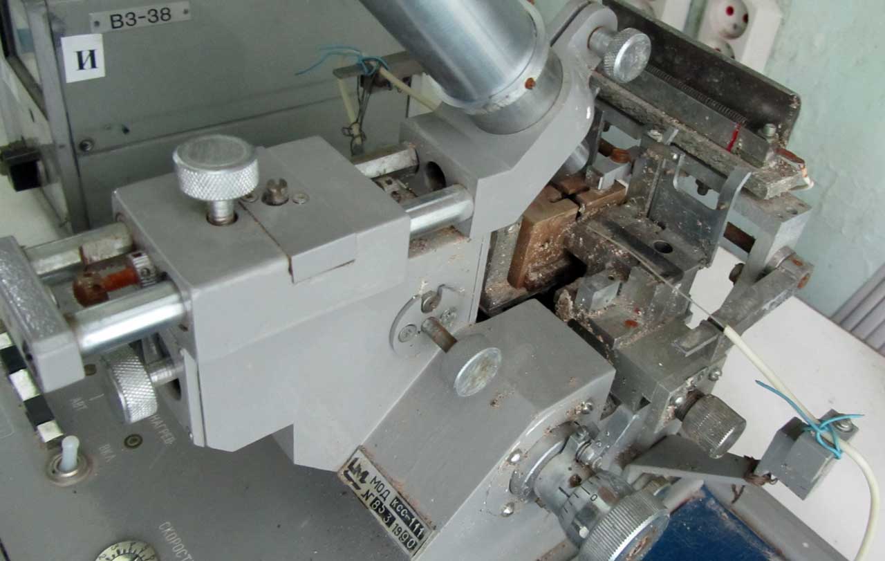
6) Old Soviet vehicles . They had some significance in the 90s, when the mass optics was just beginning and they could somehow cook the multimode “just to work.” They are irrelevant now, since the attenuation is large with modern standards (preferably 0.2 dB single-mode welding and 0.1 multi-mode is hardly possible), welding is very complicated and inconvenient (manually mixing under an optical microscope, the arc is burning while you hold the button, “fine-tuning” of the fibers for soldering them at the time of arc burning must be done manually with more than jewelry accuracy, etc.), the probability that the next welding will be successful, small, have a lot of weight and size, no spare parts and service, native the cleaver is not a cleaver, but simply a set KT of the blade and gum in the form of a parallelepiped, they are not designed for modern fibers, and so on. Examples - KCC-111, Owl. KCC is a complete hardcore, all by hand and by eye. In the Owl, it was already possible to adjust the fibers by the signal level: before and after the joining point, the fibers in the clamps were bent and according to the principle of side entry in one of the clamps at the bend of the lamp, in the other clamp there was a photodiode near the bend. When the current from the photodiode is at its maximum, the fiber cores coincided best of all and can be boiled. True, I myself did not work on such devices, maybe the one who worked would somehow refute me.
Here are some photos of broken-down KSS-111, which stands in my university.
Personally, I worked on all Fujikurs from FSM-30S to FSM-60S, several fibers were welded during training on the “trimmed” FSM-18S (which is mixed with the V-groove), several - at some Sumitomo (probably Type-39 - I do not remember). In recent years, I have been working on the Jilong KL-280 Chinese welding machine. I will tell you about these devices mainly.
Each device has its own characteristics, its own strengths. This can be guaranteed high quality, or high welding speed, or shrinkage rate of the QDZS, or the presence of two KDZS stoves, or the presence of additional handy features, or a touch screen, or duplicated control buttons for convenient work together, or a super-increase of the welding spot, or super compact, or protected from shock, drizzle and wind, or just a bargain price. For example, Fujikura FSM-60S is a recognized leader who set the bar for quality, convenience and speed, he is not afraid of moisture, dust and moderate shocks, it is relatively compact, you can fine tune his behavior as needed, but the price bites, expensive parts and maintenance . (Recently a new Fujikura came out - FSM-80S, probably, it is more perfect than the "sixties", but I have not seen it live and say nothing about it). Chinese DVP-730, for example, is slower, less reliable, according to rumors, cameras can be unbalanced by shaking in the trunk, but the price is three times (!) Lower than fujikur. But Jilong KL-300T - in the opinion of many, the best option: in fact, the reworked clone Fujikura FSM-50S costs much less than Fujikur and Sumit, has good reliability, cooks almost as well as Fujikura flagships. And if someone needs compactness? Then his choice - Furukawa Fitel, or simpler - Fujikura FSM-12S. In short, for each task there is the most suitable option.
Why, with such a variety, many strive, despite the price, to buy an expensive welding machine, preferably a Japanese flagship, which is designed for welding highways?
I suppose the point is versatility (who knows what will have to be done tomorrow - the trunk, FTTx, PON?), And also that it is possible to meet with some misunderstanding with the customer’s employees who are responsible for the acceptance of the constructed object. From a technical point of view, it is clear that if the FTTB type network with its short distances or short lines for a dozen kilometers of attenuation in welding is not particularly critical, then for highways under a hundred km the loss of 0.15 dB in welding is already a crime. However, those who accept work, especially large customers, often do not want to hear anything and demand that any line (not fiber, but the entire finished line from cross to cross) fit into attenuation values not worse than 0.22 dB / km of attenuation at a wavelength of 1550 nm and 0.36 dB / km at 1310 nm, and indulgences do not give much. On the one hand, they can be understood - in fact, theoretically, through our short line, one day they can also plug a responsible highway. But on the other hand, still sometimes the requirements are too strict. It is clear that to draw the line to such indicators with a cheap welding machine is much more difficult than with a good and expensive one. With an expensive one, you just regularly welded all the couplings, perhaps, after analyzing the measurements, you went through the couplings and corrected a couple of jigs. And with a bad machine, you can run to fix attenuations for a very long time.
In general, in my personal opinion, now the coolest device is the Fujikura FSM-60S. If I chose for myself and were not constrained in the means, I would choose it (although, probably, the newest FSM-80S is even better: there, for example, a feature is declared with a lid automatically closing after laying the fibers, which saves time). If I didn’t have enough money, I would take it or Jilong KL-280 (personally tested, a good machine, cooks efficiently, the minuses are a bit more compact, slower and more inconvenient than fujikur, do not know how to cook welding attenuators with a given attenuation, there are no specially sharpened programs for welding “displacement” and new “ultra-flexible” fibers, and I heard rumors about its lack of reliability) or Jilong KL-300T (it is praised on the Internet for reliability, high quality of welds and for the fact that this is a big step forward for Nanjing Jilong compared with the former KL-280 and KL-26 0C, but I did not feel it myself).
Jilong KL-280
Alternatively, you can consider second-hand Fujikura 50S or 60S, but second-hand is second-hand, you can run into a device with some hidden, hard-to-reproduce defect, and there is no guarantee (as my dad says, what kind of fool will sell you a good one? ), and buying such an expensive tool is still not buying a mobile phone with it. I would not buy FSM-30S, FSM-40S and other old devices, even get caught a new copy left over in stock: the price for them will be almost the same as for modern Japanese flagships, they are too slow, old, with electrodes and spare parts can problems arise, the batteries there are nickel-metal hydride (instead of lithium-polymer or lithium-ion on modern devices) and weak.
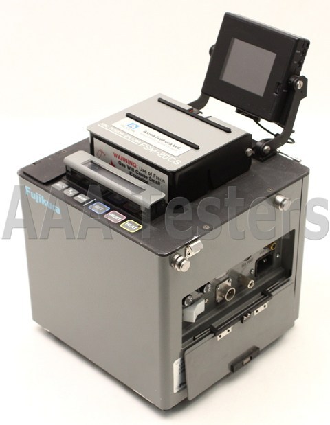
Fujikura FSM-20CS: demon of the ancient world!
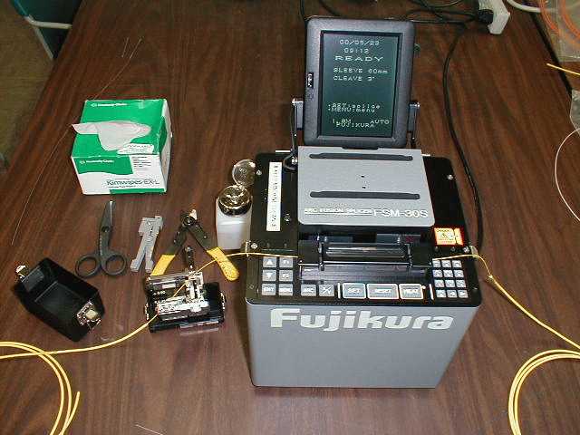
FSM-30S. Slow, old, for welding you need a lot of movement, but it seems to be cooking quite well.
Of course, my picture is not the most complete; for the full picture, I would have to boil on Sumitomo (also excellent Japanese machines) and Furukawa Fitel, on INNO Instrument, as well as on other Chinese. A complete picture could be given either by a fitter from a large company with a large fleet of different devices, or by one who sells them.
Welding machine must be protected . I think this is obvious, remembering how much it costs. If you buy a device, but others will work on it - you need to impress this on future employees. You need to protect it fanatically, as the apple of one's eye! Ponder every step. Is it worth it? Is the desk secure? Will something fall on him from above? Will a gust of wind blow this dust from the road to the workplace? Is the storm going? If going, did I take a tent? And what will happen if someone from the passers-by pulls the cable being welded out of the working tent, will the welder fall from this? Wouldn't those guys in shoes and tracksuits want to get to know fiber welding more closely? And so on. I always try to sit down at the welding machine with the same feeling that I used to take a mobile phone in my hands when I was a schoolboy without money in the early 2000s ... :) It’s undesirable to store and carry the machine without a case: it is not a coincidence that the case is decorated with a thicker inside foam plastic. Although on tests FSM-60S the Japanese dropped it from a meter height and then she cooked, I do not advise checking.
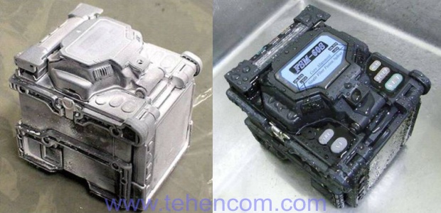
Fujikura FSM-60S tests with dust and water
The same applies to the cleaver: the basis of the cleaver, like the cases of hard drives, is made of soft metal and is covered with easily stripped paint or anodizing / burnishing, and this is no accident. It can not be hit or dropped. There will be a dent and a flayed paint - guarantees end. It is also impossible to touch a circular knife with fingers and other objects, the fibers should be laid very carefully, one movement with curved hands can lead to a cut of the finger and a minus of a resource of several thousand chips (if the knife is partially blunt). This also needs to be followed closely and fanatically. It is impossible that he rusted in the damp. I and my partner can be proud: our skalyvatel for 3 years of extreme attic-basement conditions never fell.
The welding machine also periodically needs to do maintenance of a different “level”: the minimum is to do the cleaning of the electrodes with a powerful current, calibrate the arc position and calibrate the amperage in the arc.All this is done programmatically, through the menu, and everything is described in the instructions. This is the case with our current Jilong'l KL-280, the Japanese are a little different, there are separate self-testing programs. It is advisable to run these tests every time before starting work, if after the previous calibration the temperature / humidity of the air has changed (affects the arc) or many weldings have been done from the previous calibration (the tips of the electrodes have worn off a little).
Sometimes require replacement electrodes (after several thousand welds) and battery. Sometimes it is necessary to clean the dust (by the way, it is forbidden to blow it with a can of compressed air - too sensitive mechanics). Sometimes something breaks, razustirutsya, and requires a full repair in the service center. On some Chinese after 9999 welds (a very impressive volume), the device is blocked, demanding to carry it to a service center for full service.
As for the electrodes, that is, of course, the welding volumes recommended by the device manufacturer, after which the electrodes should be changed. However, in fact, many solders weld all the way until bad welding and unstable arc start. There is a little secret with electrodes: you can extend their life by a few more hundred welds. The fact is that the wear of electrodes is a complex thing. Partly, it lies in the fact that a layer of glass is being sprayed onto the electrodes from the fibers being welded. Partly - in burnout "funnels" at the tips of the electrodes, which leads to an unstable arc. So, the crumbs of the sprayed glass can be knocked off with a razor, what is left is to be removed by cleaning in the eraser. Only the gum needs to choose "gentle", without abrasive elements, otherwise the electrodes will have to be thrown away almost immediately.
After replacing the electrodes, it is imperative to run the appropriate calibration.
Electrodes for the welding machine
Here we got acquainted with the fact that such a modern device for soldering optical fiber, what these devices are. Let us return to the description of his work in more detail, when we further weld, shrink and lay the fiber. And now we will get acquainted with optical fiber cleavers.
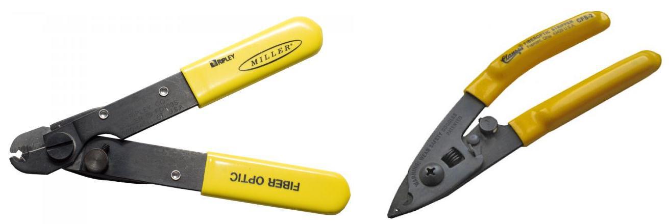
Cleavers
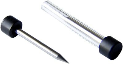
The optical
cleaver device The cleaver is a mechanical precision device whose task is to chop the end of the optical fiber so that the cleavage plane is as even as possible and perpendicular to the fiber itself. Although there are specialized cleavers with electronics, and allowing you to make cleavage angles different from 90 degrees, I will not consider them here.
The quality of the cleaver is determined by the following statistical parameters: how smooth the cleavage is, how much the cleavage angle differs from 90 degrees, how often the cleaver breaks the fibers, how convenient it is to work with it, what the resource is.
Why do we need a cleaver? If we just break off the tip of the fiber with tweezers, then the probability of a good cleavage will be extremely small, and welding is guaranteed not to work. Here are a couple of examples of bad chips (as well as a picture in the cap of the article):
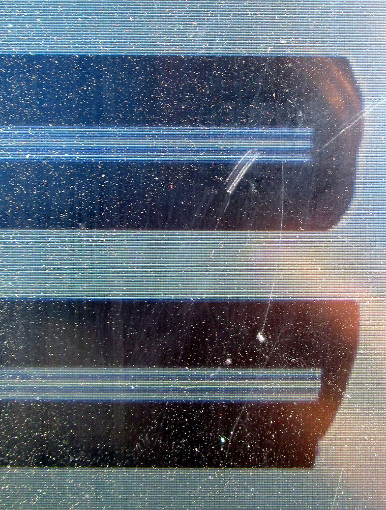
Bad chip on the screen of the welder (view of the same fiber from two cameras). On the screen, working dust and scratches. ;) Therefore, I do not peel off the protective film.
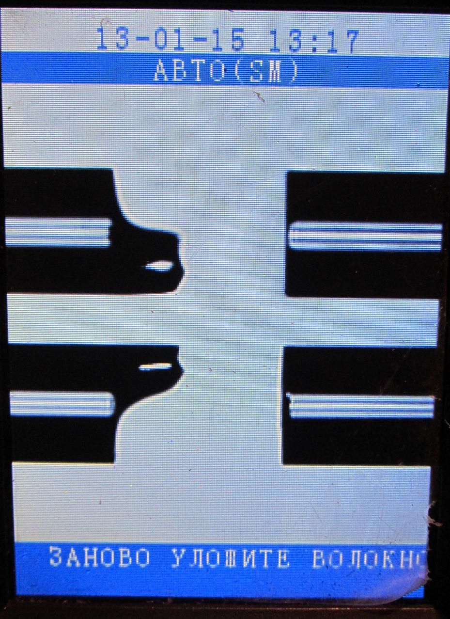
The left fiber has a bad cleavage, the right one is normal (a small black defect, which is a frequent phenomenon on the right fiber, it usually does not affect welding, as it is located on the edge of the fiber).
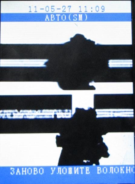
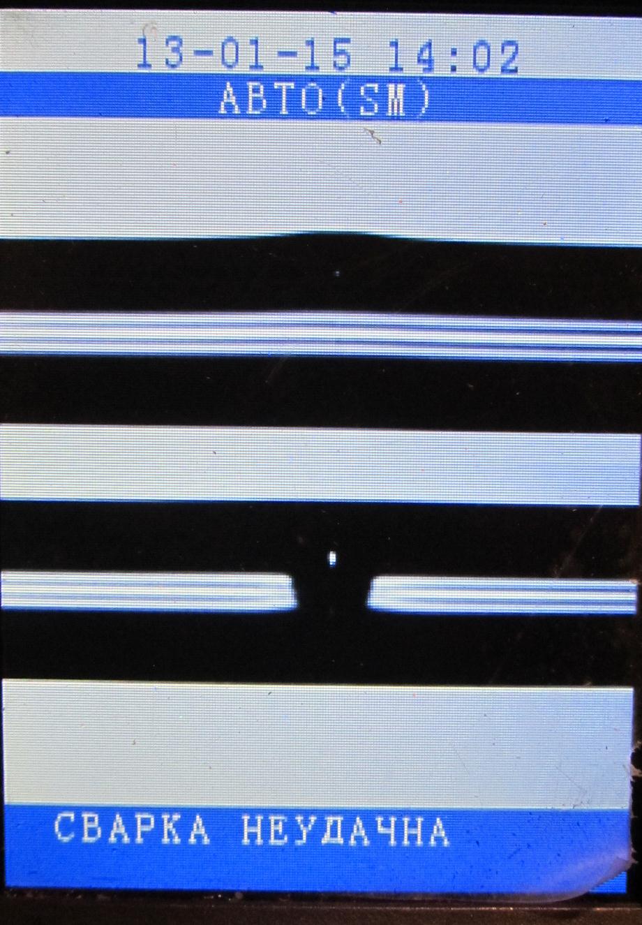
And welding (if we force a smart welding man to force a weld despite the protests) will look something like this:
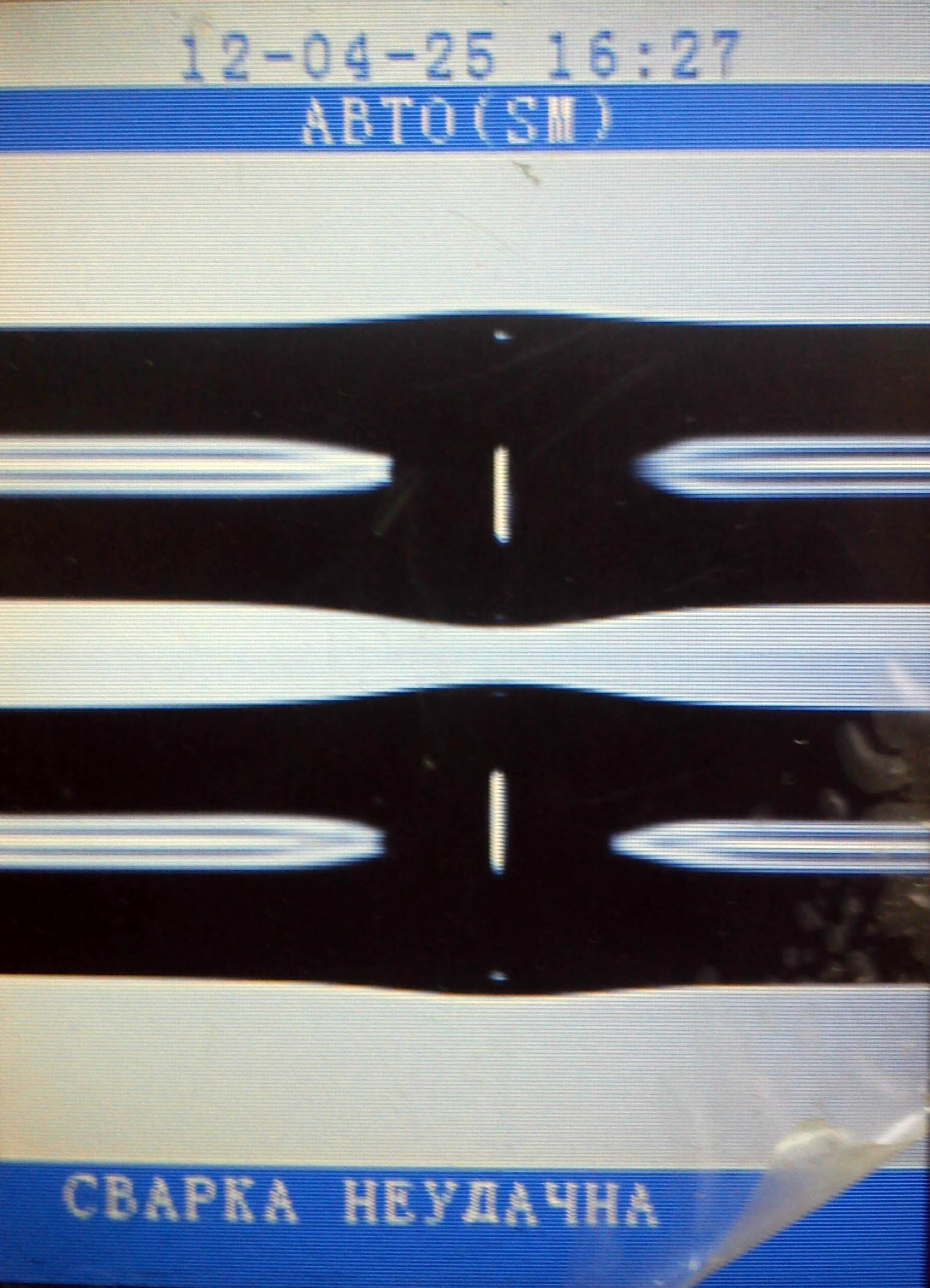
The typical "bubble". Welding is subject to rework. The line with such welding will not work. At best, if the line is short, it will rise with a bunch of packet loss, but the attenuation here will be several decibels.
Therefore, we need a special tool to carefully prepare the fibers for welding.
Cleavers, like welding machines, are different. More expensive, cheaper, much cheaper, highly specialized, historical. With a container for chopped fibers and without such. I probably will not be able to give a full review of all existing clearing systems, since I worked with only two models. So I will describe what I worked with. In short, my opinion is this: if you can compromise with a welder and save about a hundred thousand rubles by buying a good “Chinese” instead of a Japanese, then it’s better not to do it with a cleaver. Yes, yes: if you buy a Chinese “whale” with the attached Chinese skalivatal, I advise you to purchase an additional good Japanese cleaver, and use the “whale” cleaver as a backup (or as an extra, to speed up the work). A good chip is already 50% of successful welding, and the speed and convenience in work is the key tothat the welder will have time to cook more in a day. So, having invested an extra 20-30 thousand, not very noticeable on the background of the cost of the welding machine, reflectometer, car and other equipment, we will increase the convenience, quality and speed of the solder. Although, of course, if the goal is to form a mini-brigade to service the provider network with a minimum budget, where convenience, speed and quality are in the background, and you do not plan to build first-class highways, you can save money by using stock whalers.if the goal is to form a mini-brigade to service the provider network with a minimum budget, where convenience, speed and quality are in the background, and you are not going to build first-class highways, you can save money using the stock whale skalyvatel.if the goal is to form a mini-brigade to service the provider network with a minimum budget, where convenience, speed and quality are in the background, and you are not going to build first-class highways, you can save money using the stock whale skalyvatel.
Here are some examples in pictures.
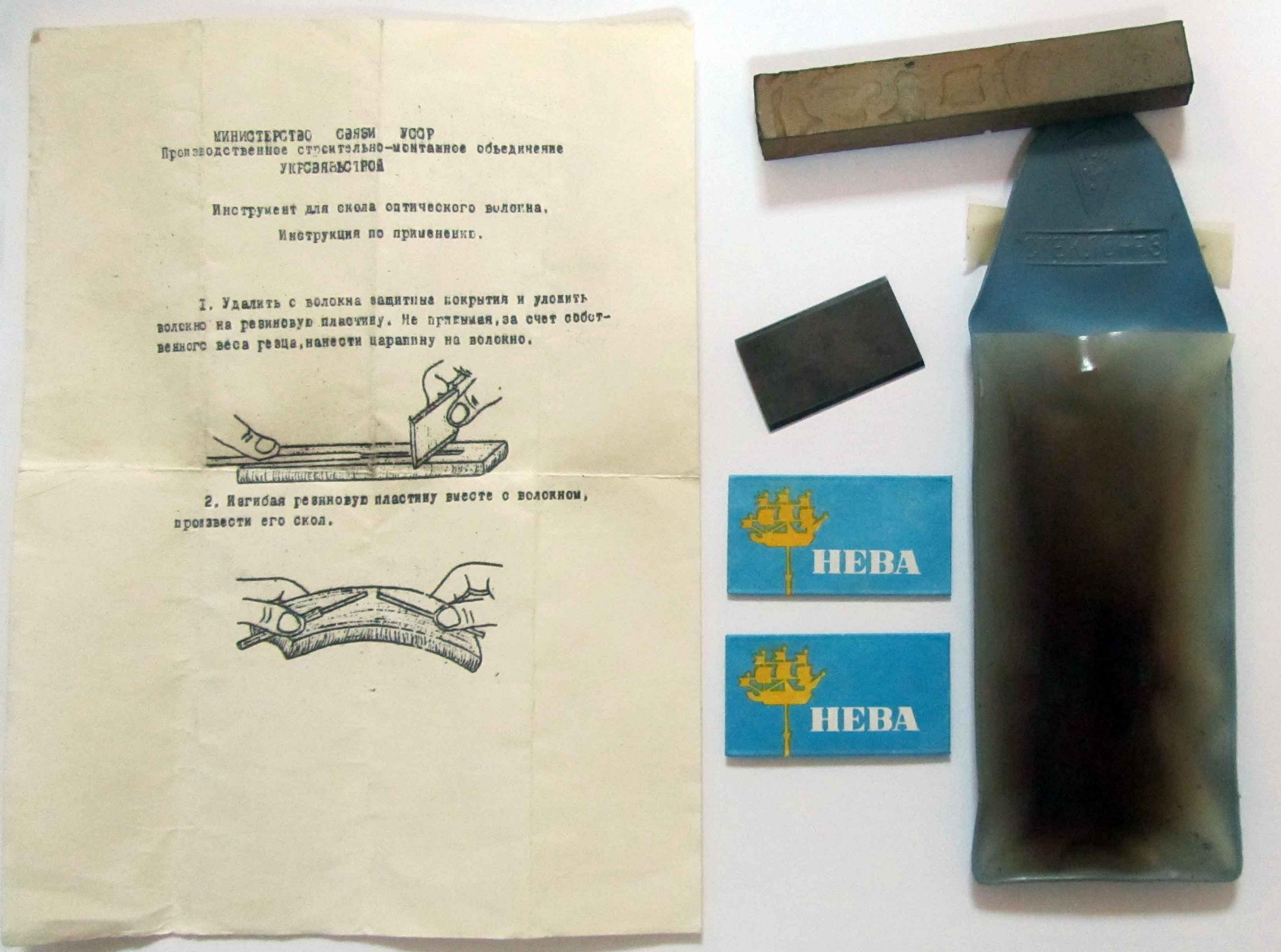
Soviet Cleaver! Blade, gum, case and instruction. Razors are in addition. Thanks to the boss for keeping such an artifact. By the way, such thick fibers were not to be held in the hands. Tried for the sake of experience in the same way (new blade and soft eraser) to chop up modern fiber - the attempt failed.
Jilong KL-21C while cleaning
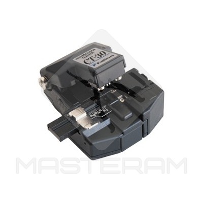
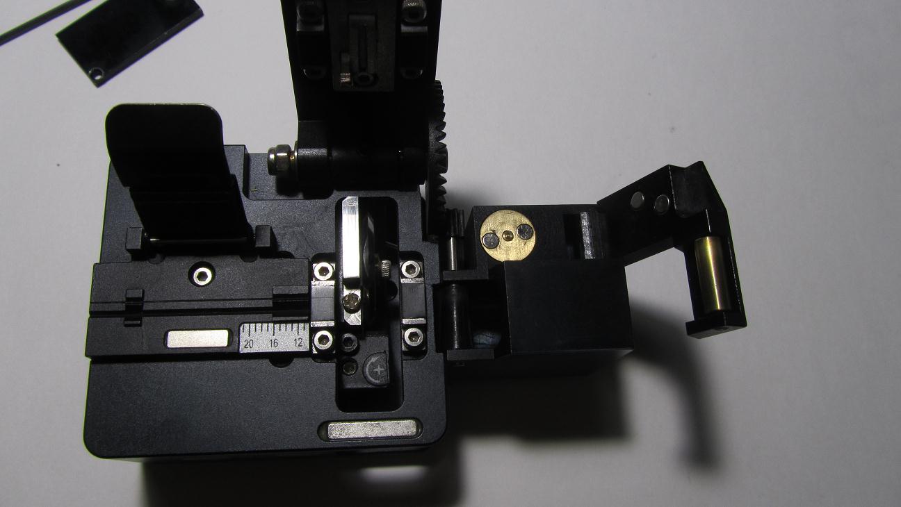
Fujikura CT-30

Punches INNO Dragon. With printed pattern!
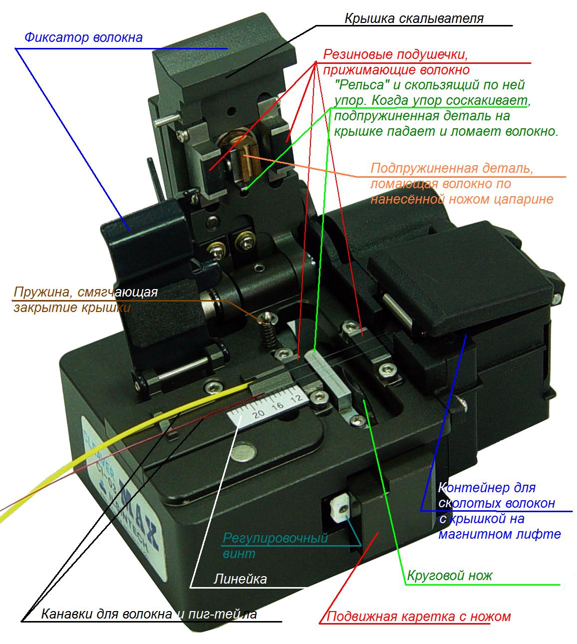
I will describe the first cleaver, which I worked. This is an example of a good, time-tested cleaver. This is the Fujikura CT-30 / CT-30A.
Very many solders have this particular model. I worked with this and say that this is a really good, thoughtful and convenient device. It is compact, reliable, for cleaving you need a minimum of movements, you do not have to wait for surprises from it. Only it is necessary to take necessarily with the container for the chipped fibers. Unfortunately, my boss does not buy it for me, I have to work in Chinese. There are also other models of Fujikurovskiye skalyvatel, which are positioned as a more modern, compact and cheap, but by no means less quality replacement CT-30A. But still, the CT-30A is a classic.
Another cleaver, on which I worked and which I now have is the Chinese Jilong KL-21C, which was in the set with the Jilong KL-280 welding machine. This cleaver performs its task, but I have a number of complaints about it. For example: the number of actions to be performed for cleavage. The Chinese have it more than the Japanese. In the case of the CT-30A, we need to:
1. Load the carriage with a knife.
2. Lay the fiber.
3. Close the fiber retainer.
4. Press the cover to make a split.
5. Open the lock.
6. Remove the chipped fiber.
In some cleavers, even fewer actions are needed: even the carriage is not needed to be cocked, it is cocked when the lid is opened and produces a working pass when it is closed.
In the case of KL-21 you need:
1. Cock the carriage with a knife.
2. Lay the fiber.
3. Close the fiber retainer.
4. Close the lid.
5. Manually push the carriage with a knife, producing a chip.
6. Open the cover, breaking the force of the magnets (uncomfortable with one hand).
7. Open the lock.
8. Remove the chipped fiber.
It would seem that only 2 extra actions. But this is ergonomics, this is time, this is the amount of work that can be more during a working day if all operations are done quickly.
Then, this cleaver sometimes breaks the fibers, and cleaning, blowing is not particularly helpful. You chipped it twenty times normally, you took out the fiber on the twenty-first — and it broke in one of several places that were loved by the cleaver: before or after the rubber pad, or between the pad and the knife. We have to clean and wipe with alcohol again. I fully admit that someone did not come across this, but fact is a fact.
In the cold and damp, for reasons that are not completely clear to me, it begins to prick worse and break fibers more often. It got to the point that you stand at night on the side of the road in mud under snow and rain, all wet and angry, almost welded coupling is laid out on the hood of the car, which must be completed, not less shaky comrade with a cardboard with one hand covers the welder from precipitation, with the second hand it shines with a flashlight, and then, as luck would have it, 2 of the 3 fibers break, and you have to redo them with fingers.
The resource of a circular 16-position knife in a Chinese cleaver is rather small: you often (in comparison with Fudzhikurovskiy) have to turn to the next position, otherwise it starts to prick badly. When the knife has passed a full turn, its corresponding adjusting screw is raised to some microns and it passes the second turn. After that - the second lift and the third turn, then the replacement of the knife.
The full resource of a good Japanese cleaver is somewhere around 48,000 chips. That's what Japanese steel means! ;)
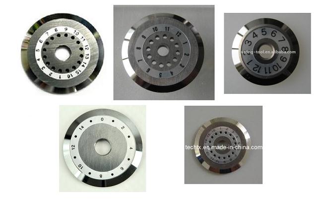
Circular knives for all kinds of cleavers. Mutual scale is not respected.
There are other cleavers. For example, cheap under-cleavers in the form of clothespins, which do not provide accurate cleavage perpendicularity and which I would not advise to use.
The working principle of the cleaver is as follows:
1. The fiber (trimmed from varnish and rubbed from dirt) should be well fixed.
2. At the time of shearing a transverse micro-scratch is made on the fiber with a diamond knife or a knife made of hard steel.
3. A force is applied to the fiber so that it cracks exactly on the scratched spot.
In different models, the technology of producing these operations is slightly different, and I cannot show the splitting process visually (for this, I would have to draw a slow-moving semi-transparent 3D animation of the splitting process in some 3DS MAX, where every detail is tinted with its own color). But I will try to explain in general and show on the video.
Let us consider in more detail the splitting of one fiber on a typical cleaver.
1. Optical fiber is trimmed to a certain length, well wiped with a lint-free cloth with alcohol. Do not touch the glass with your fingers!
2. Open the latch and cover and carefully lay the fiber in the cleaver. At the same time, it is important to keep the fiber clean and not to get into the knife with your fingers! The fibers in the lacquer shell are laid in a thin groove, and the pigtails in the yellow shell are laid in a thick one. You can not put a completely thick patch cords; if you need to weld a patch cord, you need to cut it up like a cable, freeing the fiber.
3. The fiber must be laid in such a way that the border between the lacquer coating and bare glass lies on the number we need on the ruler. This figure tells us how many millimeters of bare glass will stick out of the varnish after cleavage. For each welding machine this figure is different (for example, for our Jilong KL-280 it is 16 mm), you just need to remember it for your machine. If it is laid in such a way as to shorten the length, the welder does not have enough supply range for the carriages to reduce the fibers, and it squeals and displays the error “Feed Limit” or “Re-Lay the Fiber” on the screen. If you chop it so that the opposite of the glass will remain too much - everything will crumble and cook normally, but the KDZS protective sleeve (if it is a “short” standard of 40 or 45 mm) may be shorter in length than the bare glass portion of the fiber and not protect completely bare fiber. In this case, the fiber without protective varnish will very easily break from the bend at the exit from the QDZS (with the same installation), and such welding needs to be redone.
4. We produce chipped. In some models for this purpose it is enough to press the lid of the cleaver, in others it is necessary to close it, push the carriage with your finger and open it again.
5. Open the retainer, if necessary - the lid and carefully remove the chopped fiber. Immediately, still not reaching, you can understand whether it is not broken. Now you can’t put it anywhere except in a welding machine, because if you touch anything, it will immediately become dirty. You should also lay it in the welding machine so that you don’t hook any parts and surfaces with the tip: you should accidentally poke the butt of the chopped fiber into the same V-groove or into the electrode while inserting it into the welder and you will see a ton of dirt on the fiber . :)
The fibers are dirty, besides a large speck of dust has stuck to the fiber.
Such a stained fiber, in principle, you can try to clean - first, just wipe with a napkin, and then poke the end in alcohol, and then in a dry napkin. The probability of 60 percent, that it will then be clean and well cooked. But nevertheless it is better to re-clean and perekolit it at once, and even better - not to drop and not to soil the wiped and chopped fibers.
6. The split tip of the fiber, depending on the design of the cleaver, is itself pulled into the fiber container, it remains to stick out in the “rollers” or, if there is no container, it falls on the table next to the cleaver. Accordingly, in the first case, you just need to check whether the fiber is normally tightened into the container (too long will not fit, so you do not need to clean the lacquer 10 cm from the fiber; sometimes the fiber may somehow come off and not be pulled into the container), in the second you need a special pen roll the rollers so that the fiber is drawn between the rollers into the container like underwear in an old washing machine, and in the third one you can immediately attach a piece of electrical tape to the fiber so that the fiber sticks to it, and then paste over the fibers sticking to the electrical tape all sides. In general, EXACTLY I do not recommend using a cleaver without a container for fibers, and here's why.
Pieces of optical fiber, especially without varnish, are a dangerous production waste. In countries with better waste recycling culture, they are collected and disposed of. We, of course, have to do it, but still this is not a reason to scatter fibers after them. All fiber fragments must be carefully collected! If such a barely noticeable piece gets into the food, into the drink - you can earn a stomach ulcer or other problems. If it squeals into the body and breaks down - theoretically it can reach the heart through the bloodstream, although it usually becomes difficult to remove, a very unpleasant thorn that no X-ray will find and which crumbles under the forceps when trying to pull it out. And just fibers in clothes, in shoes, in car seats are not the most pleasant thing. Therefore:
1. No food in the workplace.
2. All fibers to the last must be carefully collected. Even if the work is done somewhere in a semi-submerged sewage basement, where there are knee-deep debris and fleas, or a knee-deep field in the dirt - this is no reason to litter with fibers!
3. Cleaver - only with a container for chopped fibers.
4. In an amicable manner, you should use protective equipment: glasses, overalls, apron. But no one does.
I personally, when it comes time to clean the container of the cleaver from the accumulated pieces of chopped fibers, I sit down at the table, spread a large piece of paper over myself and pour them into a separate bottle above it, and then carefully collect what has fallen.
But back to the cleavers.
You understand that successful cleavage depends on microns. Therefore, the cleaver must be protected from shocks, falls, dirt and curved hands as jealously as the welding machine. He is not in vain packed in a box with a soft filling.
You can not turn the tuning screws, not being sure exactly what you are doing. You can not climb inside with your hands or hard objects - there is a risk of cutting yourself and ruining the blade sharpening. It is impossible to leave the cleaver in a wet environment for a long time.
You just need to remember: the welding machine, the cleaver and the reflectometer are three indispensable things, without which the work will rise. Yes, you can suffer to cut the cable with a regular knife instead of BAT-25. Yes, you can remove the varnish from the fiber with a razor instead of a stripper. But making good scrap with improvised means is unrealistic, but it is impossible to weld the fiber.
So, we briefly examined the cleavers and the principle of their work.
Now I will introduce you to the mechanical splicing of fibers - and proceed to the preparation of fibers and their welding.
Mechanical splicing of optical fibers
Mechanical splicing of optical fibers was initially positioned as a cheaper alternative to welded joints. Over time, when the prices for equipment decreased, and the fiber quality and, accordingly, the requirements for the line parameters increased, mechanical connections became less relevant.
Advantages:
1. No capital investment is required in the welding machine (but you still need the cleaver and all the other tools).
2. The higher the mobility of the optics installer - no need to carry a large case with a welder.
3. Suitable as a cheap backup option for temporary restoration of communication, when there is no welder near or a battery is in the middle of the field, and the connection is needed immediately.
4. Usually, mechanical connectors can be installed in a standard cassette instead of KDZS.
5. One mechanical connector can usually withstand several pererezdelok fibers, and the sleeve KDZS disposable.
Disadvantages:
1. The loss on the joint is in any case much higher than in the case of a welded joint.
2. On time fuss requires no less than with welding.
3. Reliability below. Sometimes (from vibration, from time to time) the connection can be broken, especially if the fireblocks / Corelinks were already used, and you have to look for a long time and sadly, which of these damned fireblocks fell off this time.
4. The welding machine is expensive, but then the price of a single splice is small. With mechanical connectors - the opposite.
5. For many customers, such an installation - this is not serious.
In general, I read about cases when the short line was rising and almost without loss of packets worked, having 3-4 mechanical connections on myself, made without any involvement of the cleaver at all! This is only possible thanks to the immersion gel and luck (so that the chips were more or less even, and not like a spearhead). But still it is from the category of perversions, for the installation of mechanical connectors still need a normal cleaver. Then you can get at mechanical connections damping from about 0.1 dB and above: for the trunk is a lot, but as a temporary option or for a short secondary line - will come down.
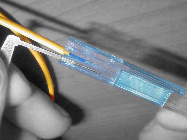
Fibrlok connector installation
There are many standards for mechanical splicing.
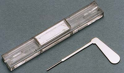
Probably the most well-known standard for mechanical coupling is fibrlok.

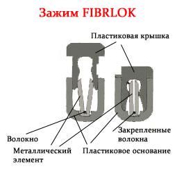
I had to see a couple of times live and even mount (on learning, really). The connector is a plastic parallelepiped, consisting of three parts. The first part is a plastic, in section U-shaped base-groove. Two other parts are inserted into it: a plastic U-shaped lid in section with a snap and a metal V-shaped groove in section with a round “bed” for the fibers not on the bottom.
Prepared chopped fibers are inserted into this groove of the V-shaped groove on both sides, usually the ends of them are dipped into a special immersion gel to reduce losses and reflections from light passing from glass to air and again to glass. An immersion gel droplet may already be inside a fayberlok. The refractive index of this gel is close to the refractive index of the glass cores of the fibers. The same gel often has hydrophobic properties.
The groove itself may be slightly bent around the laid fibers, remotely similar to the piano loops. When the fibers are laid, a U-shaped lid-holder is put on top of this groove, which, when put on, compresses the V-groove, fixing the inserted fibers tightly, and locking itself with latches.
There are other standards. For example - Corelink, I also had to see him live. The principle of operation is similar to Fibrlok, opens with a key.
I also had the first job, when I knew little about optics, to see the mounting of some mechanical connector, which was opened by a special mechanism on the bundled micro-table. What kind of connector - no longer remember, 5 years have passed.
Conclusion - there are many standards of such connectors, you can carry a dozen firelocks with you just in case, but it is reasonable to use them “for a permanent” - a big question. The welding machine, of course, is not cheap, but after a couple of large projects it will pay for itself. And the mechanical connectors themselves are appreciably, in time they are mounted as much as the welded joint, attenuation and reflections give more, reliability is lower.
So, we have considered welding machines, cleavers and mechanical connectors. It's time to continue the story about the preparation and welding of optical fiber.
Optical fiber preparation
In the first part, we stopped at cutting the cable, wiping the fibers, preparing the coupling (or collecting the cross) and putting the cable into / into it. We continue the installation. However, before the welding process, something else needs to be done.
The next critical step is the labeling of the modules and fibers . Actually, the cable should be marked before entering the coupling, otherwise it will not be so convenient, I just forgot to write about it in the first part. But it is necessary to label the modules. If you do not do this - then you have to twitch which fibers go to which module. Believe me, this is very inconvenient and easy to make a mistake.
For marking such paper or rag stickers-markers are used.

They are often sold in the form of a notebook with such sheets or in the form of ten drums, on which ribbons with numbers from 0 to 9 are wound. Usually they are included in the set of couplings, less often - in the set of cross.
A very common and, at the same time, difficult to detect and unpleasant mistake of newcomers (and even experienced at times with this) is to confuse the modules. Red (first) and second modules are difficult to confuse, but white / natural / colorless - easily, they are of the same color ... This is the very case when you can’t overlook a stupid mistake. Therefore, check seven times - mark and solder once.
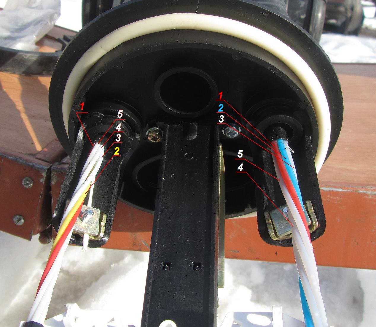
In these pictures, I schematically painted a cut cable and the principle of marking its modules, and also showed an example of marking a real cable.

Modules are labeled as follows.
They usually have a color marking, which is indicated in the cable passport. Nevertheless, the first module is always red, I have never met any exceptions. Here we are on the clean worn fibers coming out of this first module, and immediately glue the number "1".
The next module will be the one that is “colored” and costs about red. About red, of course, costs 2 modules, left and right, but on the other hand there will be either white (it’s also natural, it’s also colorless - it’s written differently everywhere), or a black (or also white) dummy module. So, the one around red and “color” (usually yellow, green, blue) will be the second. We glue the number “2” on its fibers.
The third module may depend on the cable as another color or white / natural / colorless. It is important to understand the following. The first two modules, by their location, have already given us the direction of “walking around” in a circle of modules in the cable - either clockwise or against. So we continue this direction and glue the figure “3” onto the fibers of the next module. Red - the first, color - the second, the next after the wind - the third. Another one following in the same direction of “walking around” in a circle, usually colorless — the fourth, and so on.
Everything is so simple. But modules are often confused, and it can be very difficult to find and eliminate: if there are a couple dozen couplings in the line that you have to open, many of them are buried a couple of meters in the ground and corn is eaten above them or arable land is washed away by rain - you know, what a torment with shovels in the heat to correct such a joint.
How to find a place where modules are mixed up?
The "jumble" is defined as follows. Suppose we have a straight line: 2 crosses and several couplings between them.
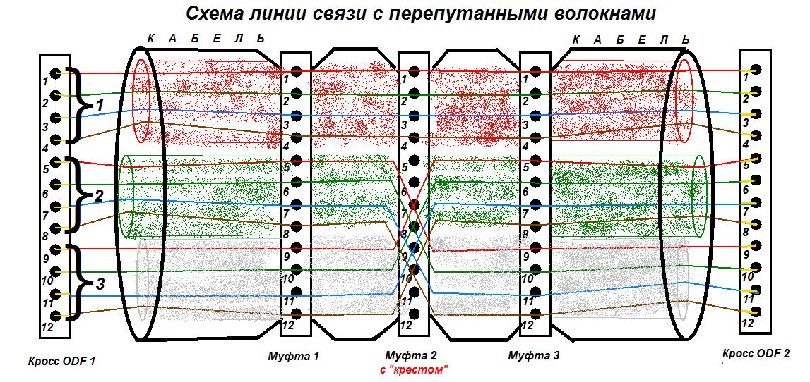
At one cross-over one becomes a person with an optical radiation transmitter with a length of 1310 or 1550 nm, at the second cross-over becomes a person with a receiver-tester at which he exposes the same wavelength. They put both the receiver and the transmitter on the first ports. If the fibers are not mixed up and the first port on one crossover really arrives at the first port of the second crossover, the tester will show some signal level. And so, having phoned to coordinate actions on the phone, they “pierce” all the ports on the crosses.
By the way: in the old days, when there were no cell phones yet, and the optics were already being pulled, so-called optical telephones were used: a pair of tubes with batteries, tuning knobs, a microphone, a speaker, and one or two FC or LC connectors. You can talk, standing on a pair of free fibers or even on one fiber (in this case, reception at 1310 nm, transmission at 1550). I used it once. Now, in general, this is not necessary, because, firstly, there are cellular, secondly, many multiplexers have a built-in telephone for communication between network nodes, and thirdly, there is a landline telephone at many communication centers. But in principle, it may sometimes be necessary in such a device.
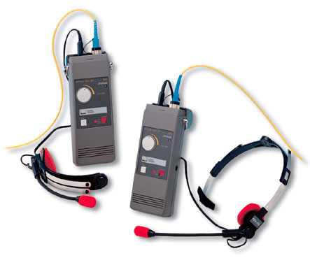
Optical phones
Let us return to the search for "crosses" on the line. If there is a “mix-up” - it becomes immediately clear: starting from some port (in our figure - from the fifth), the next port goes to the “transmitting” cross, and there is no signal on the second “receiving” cross, but it (and the next n ports) is in the port with a shift by x * n ports, where n is the number of fibers in the module, x is the number of modules that “jumped” (in our case, n = 4 fibers in the module, x = 1 ( 1 module jumped to 1): ports 1 to 4 pass as it should, and the 5th comes on the 9th, 6th to the 10th, and so on.
In an amicable way, in the event of an interchange, it is necessary to open and sort through all the couplings. You can, of course, simplify the task of finding such a joint: open the clutch in the middle of the line and manually check it by pulling the fiber from each module. If there is no interchange on it, then you need to carefully (so as not to break) bend the fibers on it one by one from the module (say, the first of the first module, the first of the second module, etc.), and the partner with a reflectometer at the cross will look, shortened line or not. (Remember that a strongly bent fiber loses radiation at the bend and does not let the signal through). If exactly those fibers are shortened, which fibers should - it means the joint is farther between the opened coupling and the far cross. If, for example, we bend the fiber from the third module, and the similar fiber from the fourth module is shorter, then the joint on some coupling between the cross-country, where the OTDR is, and the coupling opened by us. We close the clutch and go to open up some kind of clutch between the cross and just opened before that and repeat everything. For such works, it is very necessary to have a wiring scheme and a line scheme on which the distances from the crosses to all the couplings will be indicated.
If the desoldering scheme is complex, there are a lot of "triple" (or "tap-off") couplings in the line, cables with different colors of fibers and different numbers of them in the modules are soldered - the task becomes much more complicated. At this point, you will have to collect brainstorming, seriously turn on the brain and sit over the schemes, developing the most optimal search plan for a coupling with a switch.
But if in such a complicated line there are 2 or more places where the modules are confused, then ...
... solders need to train more, and not to cook large complex objects at once. And the best wishes can be conveyed to the designers of such a complex wiring scheme.
No - you can, of course, fake: stupidly tweak / twist the pig-tails from inside one of the crosses so that all the ports come at each other in accordance with the scheme. But firstly, the customer at the acceptance can look into the crosses, and secondly, it turns out that we rent the line, part of which is unsoldered as it is, and not according to the documentation. A year later, some of the fibers in the line will be sold, some will be leased to any providers, FSB, transport workers and other organizations. Someone will need to weld something into some of the sleeves, cut the corresponding module to solder to it, and there it turns out that the signal goes not through the fibers that it should, and we cut the wrong module and dropped then trunk DWDM !!! Which is sure to be unreserved! Or, alternatively, it turns out that we have cut off the FSB connection.Or dropped cellular over a large area. Or the Internet + phone from a villa of a deputy. Three-story and lengthy curses from the service of operation to the unfortunate builders are guaranteed! And then who knows, maybe depending on the damage for a break in communication there will be a lawsuit. And who will then hire such a contractor who has passed the line with a hidden defect? Do not do such things to your fellow telecom operators: if you have mixed up the modules, you need to find and fix the lines before putting them on.surrendered line with a hidden defect? Do not do such things to your fellow telecom operators: if you have mixed up the modules, you need to find and fix the lines before putting them on.surrendered line with a hidden defect? Do not do such things to your fellow telecom operators: if you have mixed up the modules, you need to find and fix the lines before putting them on.
There is a light version of the exchange: when not modules are confused, but a pair of fibers. For example, in low light you can easily confuse white and gray fiber, gray and colorless / transparent, white and light pink, green and turquoise, etc. At least it is easier to find: if the coupling in the cassette is signed, where are the fibers and where you go, you can simply open the clutch and compare with the scheme to see which color is on which fiber is boiled. But if the couplings are difficult to access, there is still little joy.
So you have seen how unpleasant an error is with mixed modules or fibers, and how hard it can be to fix it. It is better to mark everything meticulously than to run through the fields with shovels and route finder or do gymnastics on poles with a ladder, digging / removing from the coupling pillars, and fill up the deadline for putting the line.
I'll also say a few words about the case when there is only one module in the cable and there are a lot of fibers in it. I met with such a Siemens cable, where the marking was performed as follows. When we remove the tube module, we have a bundle of fibers in a hydrophobe. So no need to rush to wipe this hydrophobic. If you try to separate the fibers without rubbing, it turns out that they are going in two or more groups, each of which is wrapped in a “spiral” of a thread of its own color: say, blue and orange. The step of the thread at the threads is large, so by wiping the hydrophobic, we can easily break the thread marking and mix such “sub-modules”, we will have to cut the cable again.
Go ahead.
We marked the fibers on all cables. But if we cook the cross, we do not solder the cables between each other, but we digest one cable into the pigtails of the cross. I recommend these pigtails to also mark everything with the same self-adhesive dials. You can not do this, but during welding you will have to divert attention also to whether the correct pig-tail is taken. Of course, this is easier than pulling the unmarked cable module, and in case of an error, the pig-tails on the cross-country can be easily interchanged: here it does not threaten anything. But it is better to spend 10 minutes, mark and forget. Some crosses are already collected and with marked (and sometimes even stripped) pigtails, then lucky: save a lot of time and stickers-markers.
So the modules / fibers and pigtails are marked. Now we (having already inserted a cable into the coupling and fixed it to a Kevlar pigtail, under a special clamp, for a power central element or a worm clamp to the steel frame of the coupling) fasten the modules to the cassette (having thought over which modules go to which cassette). I prefer to reel the ends of the modules with tape (but so that you can see what color the tip is), and then you should attach a couple of small screeds to the cassette at the spooled place: in this case it is difficult to accidentally pull them out of the cassette, and without electrical tape they easily pop out under screeds: the friction force at rest of lavsan-type plastics is extremely small. However, if the modules are not well otverty from hydrophobia - tape to them will not stick.
The next stage is measuring the fibers in the cassette .
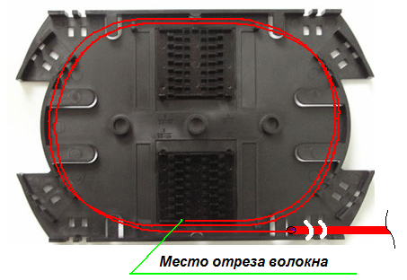
They are measured by pre-laying in a cassette and trimmed with scissors at the center of the cradle for KDZS, in which they are planned to be laid after welding.
In some cassettes (for example, as in this photo), where there are a lot of multidirectional channels for fibers, in principle you can stop measuring the fibers - there is still a “way” for laying the fibers, so that after welding it lay beautifully.
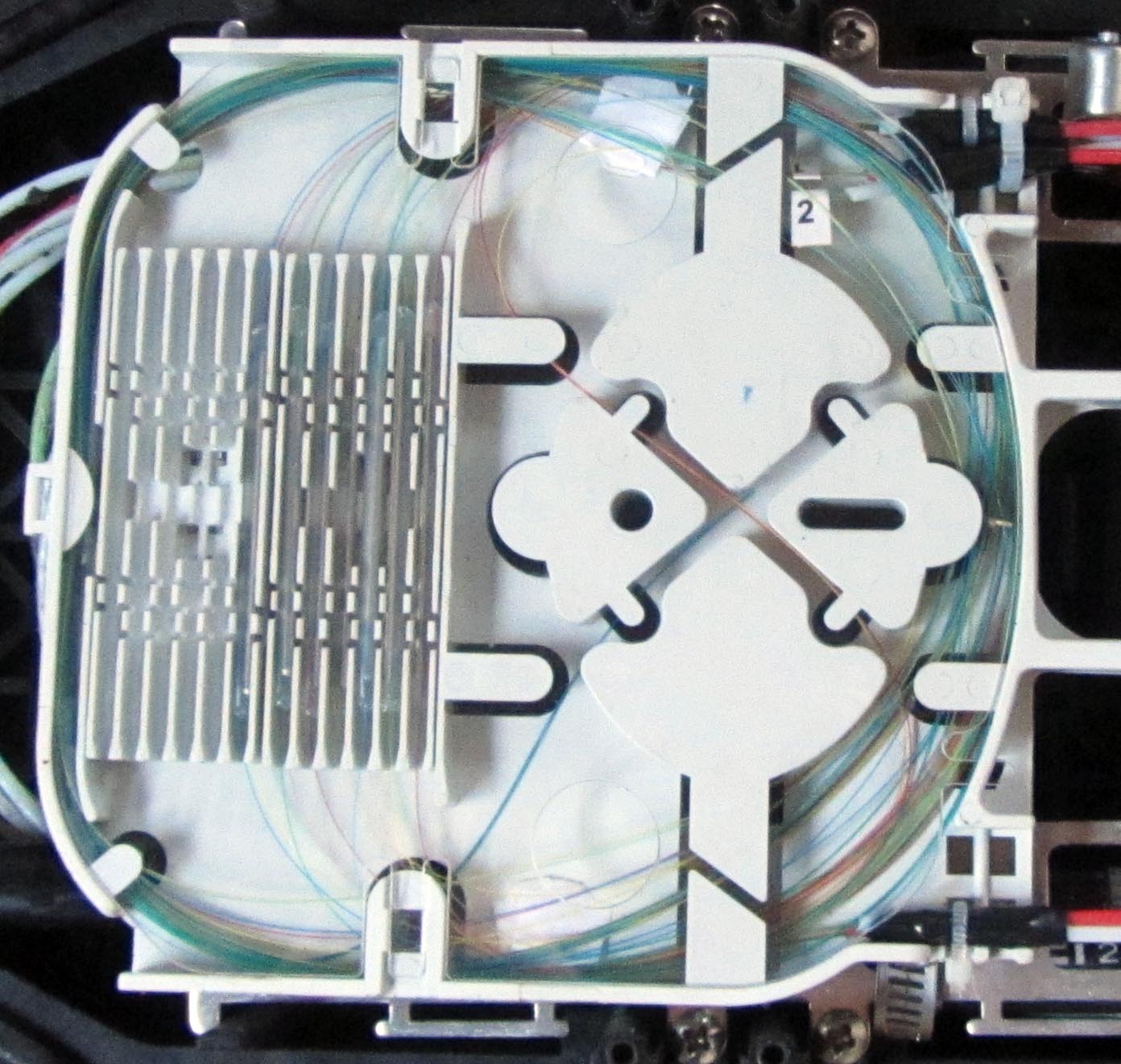
However, in the case of welding a large number of fibers, it is still necessary to measure, and it is advisable to choose the easiest way (in a circle), without tricky, complex loops and transitions through the channels. In conventional cassettes, it is necessary to measure out, because if you do not measure the fibers in advance in length and do not think out how they will lay in the cassette after welding, serious problems will arise during installation. At best (if significant reserves remain and they turn out to be “played”), the fibers will be laid out, but the permissible bending radii of the fibers will be violated, which may entail an increased attenuation for the signal, and the cassette will look ugly. At worst, the fibers simply cannot be laid in such a way that the cassette cover is closed and nothing is clamped anywhere.
This is a nightmare if you forget to measure the fibers: some of the fibers are tensioned and because of this they bend too much (there will be attenuation on the bends), some are too long and they have to be put on small radii and fixed with tape.
In the event that the two fibers that are to be welded come out of the modules that enter the cassette "counter" to each other, it is sufficient to measure each of them by simply laying
several (usually two) turns and cut them over the lodgement where it is planned to lay welding
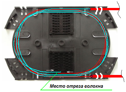
In the event that the modules come in “in one direction” (this always happens if we cook 3 cables in one cassette), one of the fibers should be measured as usual, the second fiber should be measured taking into account the transition that the S-
shaped loop in the middle of the cassette.
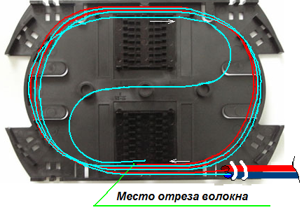
In general, the above situation with the S-shaped transition of fibers should be avoided and try to start the modules "counter", because, firstly, not all cassettes are designed for such transition of fibers, and the S-shaped transition loop of fibers (and there may be many) to fix in the center of the tape with tape that is not technological and undesirable. And secondly, it takes more time to measure the fibers. If the coupling is complex, contains several cassettes and there are transitions of fibers in the tubes between the lower and upper cassettes, the unwelding circuit is tangled, 3-4 or more cables come in, the situation becomes too complicated, you can make a mistake during installation, you will find and correct later very difficult.
You also need to consider whether all the fibers that we want to weld fit in the cassette. Consider a few cases.
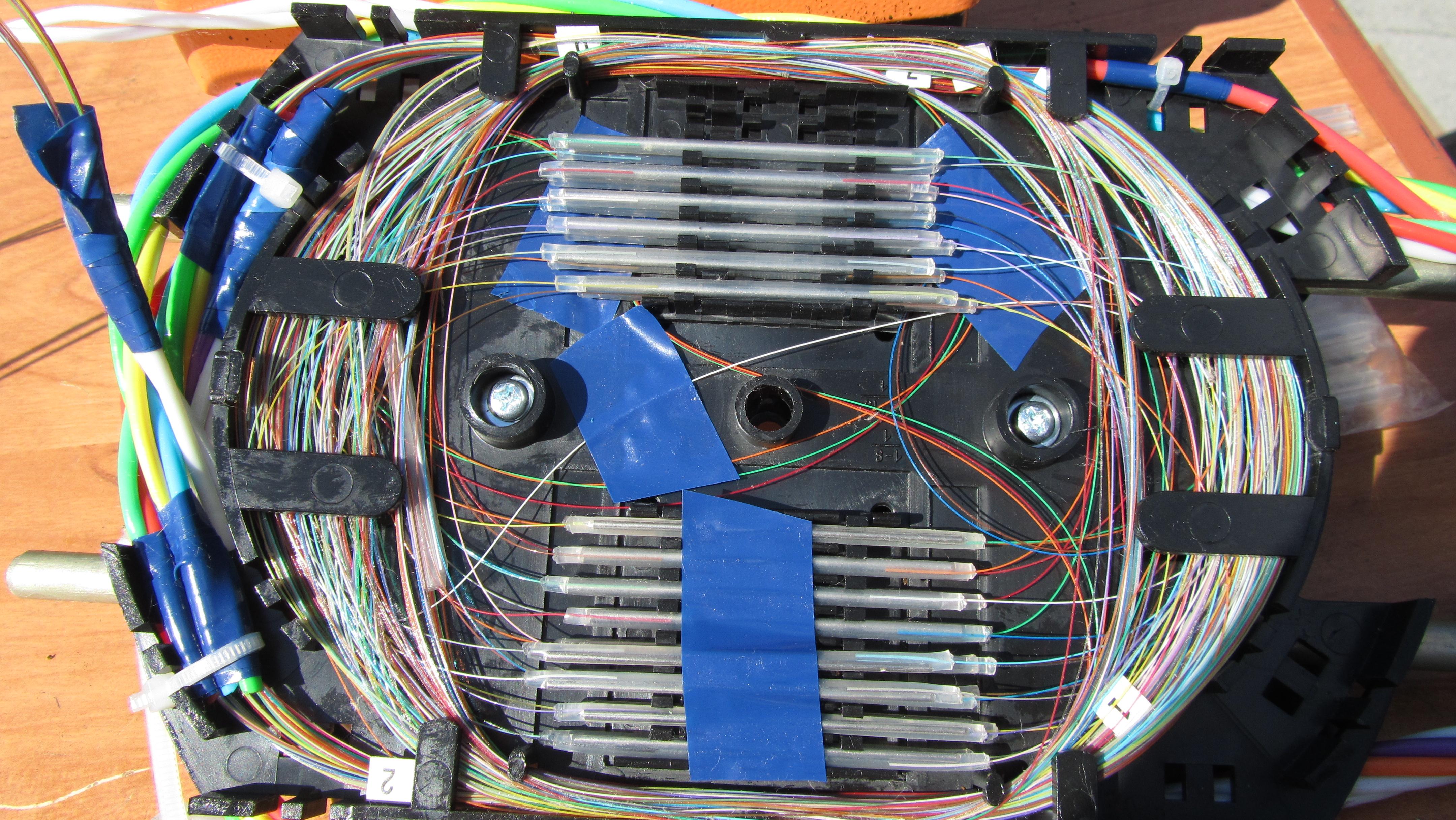
The simplest case is when you need to solder 2 identical cables, say, for 32 fibers, where there are 4 modules and in each module there are 8 fibers. A typical cassette is designed for these 32 (or there is 36 - then 4 places will remain free) of fibers. KDZS, in which the first and second modules are connected, will form in the lower half of the cassette (8 + 8 pieces, in 2 “floors”, as calculated), and the third and fourth modules will form in the upper half of the cassette. It's simple.
A more complicated case is 2 identical cables with 64 fibers, 8 modules of 8 fibers each. It will not fit in so much in one cassette, which means that half of the fibers will go to the lower cassette, half to the upper one (the cassettes are placed one on top of the other). So, half of the modules (1st, 2nd, 3rd and 4th) of both cables are installed in one cassette, the second half (5th, 6th, 7th and 8th) - in another one. The modules are fragile and fragile, but if they are fixed in the cassette well - the upper cassette can always be carefully lifted to work from the bottom.
By the way: which cassette should be placed on top, which one below? There is no definite answer.Someone is cooking the “end” coupling, then the beginning will be on the upper cassette, which is logical. Someone cooks in order. This is not so important.
An even more complicated case is when we need to weld two different cables, which have a different number of modules and different and non-constant number of fibers in the modules. Example: the first cable (let's call it A) is 64 fibers, 8 modules of 8 fibers each. The second cable (B) also has 64 fibers, but it has 6 modules, in the first and second modules there are 8 fibers each, and in the 3rd to 6th modules there are 12 fibers each. How to be in this case? We need to think carefully about how many welds we will place in each cassette, so as not to get confused - the fibers (already marked with modules) need to be further divided into “laying” groups and marked with pieces of paper with signatures. In our specific example, the first and second 8-fiber modules of cable A will be well-developed to the first and second 8-fiber modules of cable B. Great, there are 16 welds, half-cassettes are occupied. What's next?The third module of cable A is for 8 fibers, and the third module of cable B is for 12. Our cassette is designed for 32 welding, the extra 4 will
It is clear why it is better to cut the cable longer? If the fibers are short, and even 30 centimeters will eat this transition - cooking and laying such short bits will be quite depressing. And cut off the excess is never a problem.
An even more complicated case is when there are 3-4 completely different cables and an insane wiring scheme, plus work at night (during the day they did not allow the subscribers to disconnect the connection - alas, a very typical situation!) And a hard time limit. Here you need to seriously include your head, draw a plan for the location of the fibers on the cassette in advance, and in general such couplings are better not to be soldered to beginners, and you need to take them with a fresh head.
What is a transition tube? This is a common polyethylene tube. The diameter of the tube from the dropper, plastic - polyethylene (the same as the core of the gel pen, only the walls are thinner). They come complete with some couplings. If it is not, you can replace it with some kind of cambric or with the same tube from a dropper. You should not use the removed module instead of this tube: it is fragile, thin and there is a lot of hydrophobe inside. You should not make the transition of fibers without a tube either: the fibers must be protected.
So, we marked the modules, measured the fibers, thought out how they would fit into the cassettes. Next you need to put on them protective sleeves KDZS , cleaned and cooked.
Here you can act in different ways. Someone takes a pair of fibers to be welded, puts KDZS on one of them, cleans them, shears them, cooks and lays them down. Then he takes the second pair, and so on. I prefer to do it differently: I first put KDZS on all the fibers (or rather, half of them: after all, 1 KDZS protects 1 welding, which is obtained from 2 fibers), then I clean all the fibers with a stripper (but do not peg and rub with alcohol), and then just take out the wiring scheme and start cooking. He welded a group that is conveniently laid (usually 1 module) - laid. He welded the second module - laid. And so on.At the same time, we save time and are less likely to forget to wear KDZS.
What is KDZS? This is a disposable composite heat shrink sleeve that protects the weld.
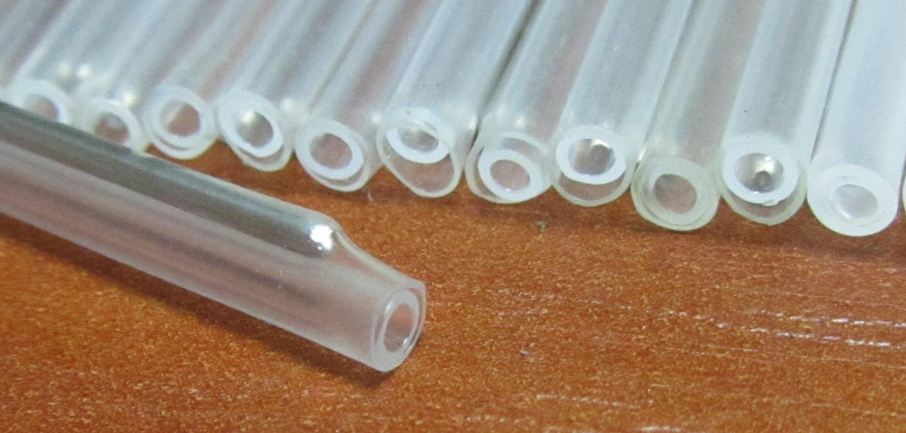
Sold dozens and hundreds of pieces, often come bundled with couplings / crosses, are inexpensive (3-5 rubles / piece). The abbreviation, as far as I know, is decomposed as "Set for Protection of Welded Joint". It consists of 3 parts: inside the tube is made of low-melting plastic, outside is a tube of plastic with heat shrink properties, and between them there is an iron wire for rigidity. KDZS is put on one of the welded fibers before welding, when the fibers are successfully soldered - it advances to the welding site so as to completely hide the glass, and the fiber in a slightly taut state is laid in the oven of the welding machine for 20-40 seconds. In the oven, the inner plastic melts, wrapping the welded fibers, and the outer one is heat shrinkable.
KDZS (and, accordingly, optical cassettes) are of different standards.
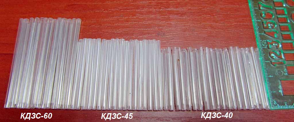
Earlier KDZS with a length of 60 mm were most often encountered, and they are now widely used. Now there are massively couplings / crosses with cassettes designed for KDZS 40 or 45 mm long. Such KDZS is better: they require less time for shrinkage, they take up less space in the tape.
In the cassette, designed for KDZS-60, you can put KDZS-40, but they will hang out in their seats, you will need to fix all the same magical tape. The KDZS-60 can also be crammed into a cassette designed for KDZS-40 / KDZS-45, but this is fraught with the following things:
1. KDZS-60, after shrinking a little thicker than KDZS-40 / KDZS-45, will hardly be inserted, respectively stuffing, you can break the welded fiber inside the plastic.
2. Often in the cassette, on the cradle for KDZS, there are column-stops, which do not allow to put long KDZS. You can, of course, bite them with side cutters ...
3. A cassette for small KDZS - and a small one. This means that a long KDZS will violate the minimum allowable bending radii of the fiber, and it will have to be placed very precisely in the center and neatly. It is necessary to shift it relative to the center of the lodgement - and the bend radius on one side will be broken, attenuation will begin at 1550 nm ... I burned it a couple of times: there were no small KDZS, I put big ones, and the customer bought small compact couplings with small cassettes under KDZS- 40 I could not understand for a long time why there were so many bad welds with attenuations in the line, I ran over digesting, and then it came to it ... I put all KDZS strictly in the center - the attenuations disappeared.
Generally, if you need to weld a sleeve with a cassette under a KDZS-45, and there is only a Kdzs-60 - as an option, you can cut off the extra 2 cm from Kdzs with side cutters. They will not become thinner, but at least get rid of the problem with small radii of fibers.
There are branded Fujikura KDZS, which sit down in a matter of seconds against 30-40 seconds for an ordinary KDZS. But I did not have to work with such.
Good KDZS - plump, thin, monolithic, neat. And a bad KDZS is soft, falls apart in hands into 3 components, after shrinking it remains too thick and climbs badly into its place, there are large gaps between the layers, because of which putting it on the fiber, you can mistakenly skip the fiber between the inner and outer tubes, what is wrong.
It happens that the welder has a stove broken, but work has to be done. Then some solders sit KDZS over the lighter. In principle, it is possible to sit down like this, but we risk overheating the QDZS and float the glass of fibers, set the KdzS unevenly, set fire to the varnish on the fibers (and it burns merrily!), And just the Kdzs will be ugly and smoked. So doing so is highly undesirable.
Only one pair of fibers is supposed to be laid in one KDZS. There are, of course, hackers who save where they don’t need, and 2-3 or more weldings are seated in one KDZS. But this can not be done. It will be necessary for some telecommunications operator to open the coupling to pull the fibers through, to see what some fiber is welded with and solder - and if he stumbles on several welds in one KDZS, he will long remember the spider and his relatives with unprintable words.
So, we marked and measured the fibers, put sleeves on them. Now you can clean them from stripping polyamide varnish .
It's all quite simple.The main thing is to do everything slowly and carefully so as not to break the fibers: remember that the fibers are measured and it costs 2-3 times to break some kind of fiber - it will become shorter and will not normally lie in the place where we intended. You need to clean it about a centimeter by 3, you need to find the exact distance by sampling and just to remember it. At first, you can help yourself with a ruler.
If it is too short, the remaining tip will be too short after splitting the fiber and the rollers of the fiber container may not catch it. If you strip too much, this split tip will be so long that it does not fit in the fiber container and will stick out of it. Both options are undesirable. However, if 2-3 welds in a row were unsuccessful (which sometimes even happens on flagship devices), the fiber becomes short and in order to save it, you have to deliberately clean it shortly, just to split the cleaver. And the remaining tip can be thrown into the fiber container with tweezers or secure it with tape.
Optical stripper is a delicate and expensive tool. His recess meets strict tolerances: he must remove varnish from the fiber without a trace in 1 pass, but the glass should not be broken. So do not snack with this stripper plastic ties and especially wires. It is designed only for stripping and nibbling 125 micron fibers.
And finally, all the fibers are marked, trimmed, equipped with KDZS. All the preparatory work is over! You can remove unnecessary cutting tools from the table, wash your hands and proudly remove our main treasure from the case - a welding machine for optics. Start cooking!
Optical fiber welding
The most high-tech part of the work. Hands should be clean! It usually takes a little less time than the preceding steps — cutting the cable, preparing the coupling / cross, of the fibers.
So, what do we need for welding? The following should remain on the table:
1. Welding machine.
2. Cleaver.
3. Pump / vial of alcohol.
4. Lint-free nonwoven napkins.
5. Prepared coupling (or cross).
6. Tweezers.
7. Insulating tape (fasten S-shaped transition of fibers in a cassette, collect fragments of fibers).
8. Scheme unwelding.
9. Stripper in case you have to re-clean and perekolot fiber.
a) Turn on the welding machine. If necessary, we perform self-diagnostics, calibration, arc test, electrode firing, and so on.
b) We take the first fiber, wipe its glass part with a napkin moistened with alcohol several times from several sides (dragging it through a folded napkin), turning at a certain angle with each pass, in order to reliably remove all the dirt. It is generally advisable to wipe the next fiber with a new napkin, if the old one is used - it should be deployed so that the new clean part of the napkin comes into contact with the fiber. It is impossible to unfold the napkin so that its side, which we used to hold with our fingers, contacts with the fiber. In general, the purity of soldered fibers is a very important point, it directly affects the quality of future welding and attenuation on it, therefore, cleanliness must be given priority.
c) A clean fiber is laid in the cleaver and cleaved to the required length. For chipping, see above, in the section about the cleaver.
d) Chopped fiber should not be put anywhere, because it must be super-clean.
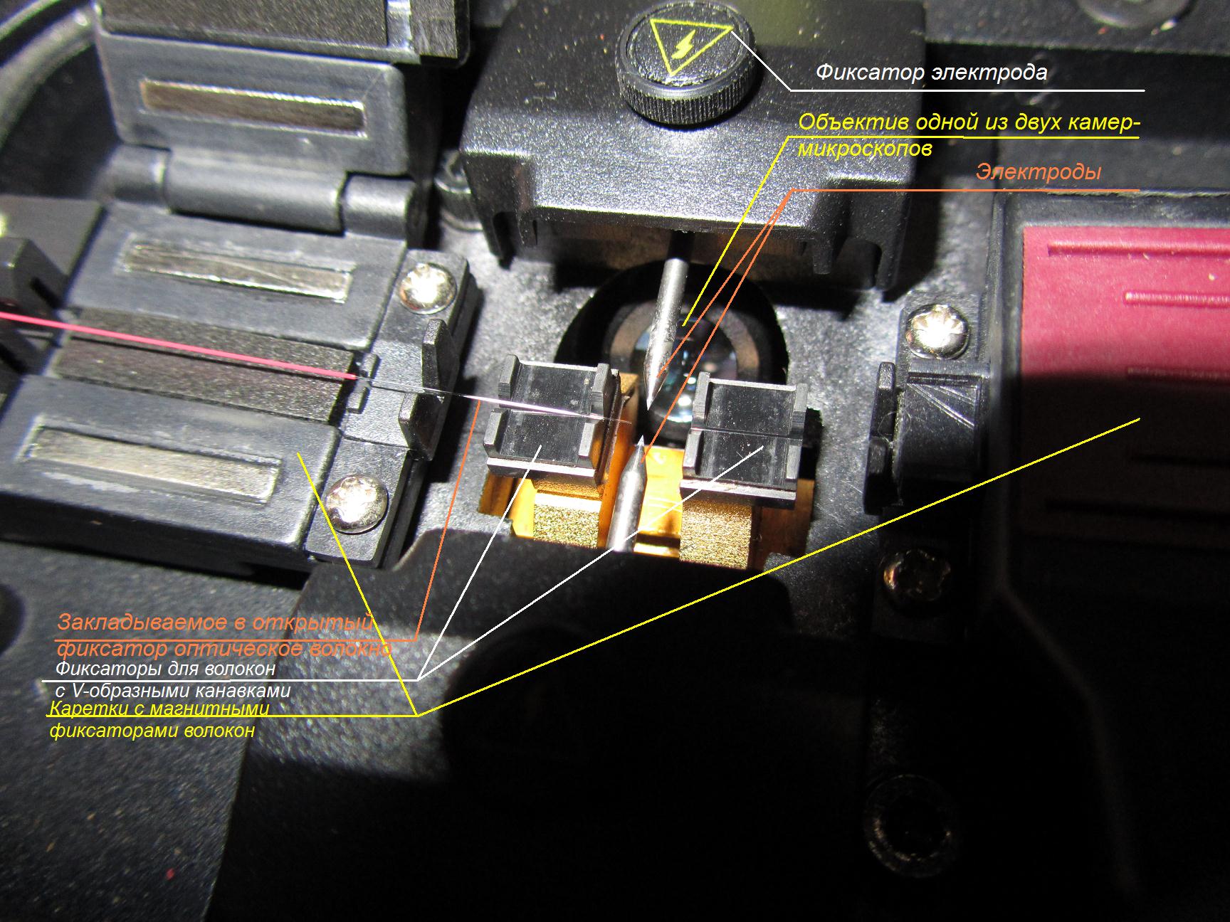
It immediately after cleavage fit into the welding machine. At the same time, it is important to put it in a V-shaped groove so as not to touch anything with the end of the fiber and not collect all micron dust from this groove on the fiber butt: we lay it carefully, holding our breath, laying - we close the lock of the mobile carriage. It is important to lay so that the end of the fiber is hung from the V-groove for a couple of millimeters, but does not cross the middle of the welder (an imaginary line between the electrodes). An example of the correct bookmark is in the photo in the first part.
If we lay in such a way that the tip will not hang from the V-groove - the range of the carriage supply will not be enough to reduce the fibers, if we set so that the tip crosses the imaginary line between the tips of the electrodes - the device will not have to be tied, but will need to be able to see the ends in the opposite direction, the carriage has no place for movement, and the device will output an error to us.
Laying the fiber in the welding machine
d) The “bd” steps are made for the second fiber.
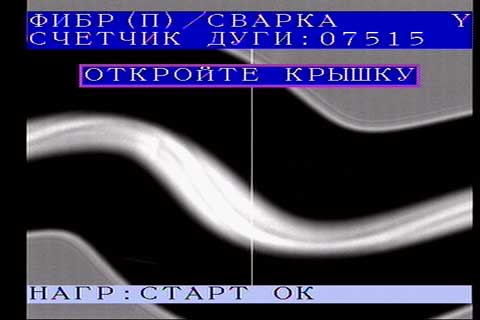
e) Press the button and the optical fibers are welded in automatic mode.
Optical fiber welding
What does the situation look like if the chipping of one of the fibers is bad
In different devices, it looks a little different. In Fujikura, the process can be finely tuned, up to the current strength in the arc and timings, but it’s better not to go into these fine settings (the welding equipment supplier often checks the password). When welding, you should pay attention to the shape of the arc (if the arc is curved and unstable - something is wrong: maybe it's time to change the electrodes, or do the calibration?), For defects at the welding site. Good welding is almost invisible, or you can see a weak stripe or some slight vagueness. Signs of poor welding are a black dot-bubble, or some axial displacement of the fibers, or a strong dark strip across the fiber at the welding point, or other shoals. If the welding seems to be of high quality, but the welding machine brings us too much estimated attenuation (say, 0.1 dB) - it is better to digest.Failed welding should be redone in any case. In case of doubt, it is also better to redo it, and not to hope for chance. After all, then you really do not want to go, dig up / remove the clutch from the post and digest one bad fiber. Although an experienced solder deliberately leaves some shoals: let's say some “closeness” of the welding site usually speaks of residual dirt melted and spilled on the surface of the fibers, and a small bubble can form not in the center, but from the edge of the fiber and not affect the attenuation. But it is better not to risk and digest.some “obscuration” of the welding site usually indicates residues of dirt that have melted and spread on the surface of the fibers, and a small bubble can form not in the center, but from the edge of the fiber and not affect attenuation. But it is better not to risk and digest.some “obscuration” of the welding site usually indicates residues of dirt that have melted and spread on the surface of the fibers, and a small bubble can form not in the center, but from the edge of the fiber and not affect attenuation. But it is better not to risk and digest.
However, in the case of a large object with dozens of couplings / crosses, something still climbs somewhere and has to be completed: sometimes it happens that welding is perfect on the screen of the welder, but then when measuring it turns out that there is noticeable attenuation on it. This is due to the fact that microscopic cameras cannot cover all 360 degrees around the fiber and the joint can occasionally hide in the blind zone of the cameras.
Here are a few examples of "shoals" to be altered.
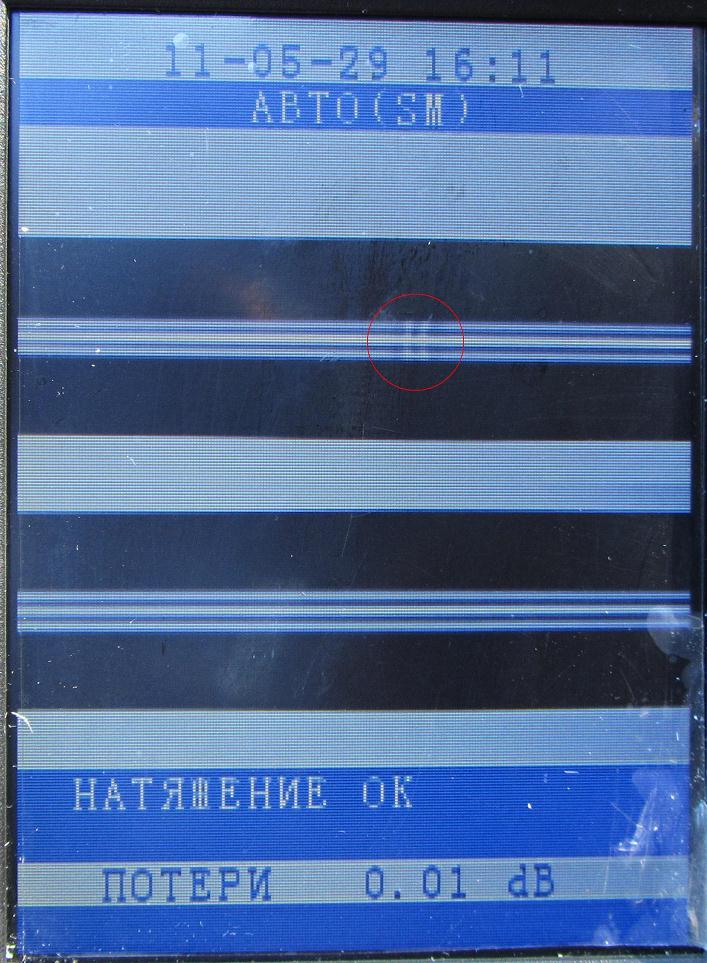
The big "bubble". We remake.
Little bubble. If it does not touch the core, there may be no damping on the welding at all, but if there is no meter with an OTDR that says “Everything is fine, continue to weld” - it will definitely be redone.
Some axial displacement of the fibers + some heterogeneity. We remake.

This happens if the arc went too long or the current is too large, or the welding somehow turned out badly, we gave the arc again, and the luck did not work. We remake.
Here, it seems, the reducing micromotors in the welding machine are faulty or uncalibrated (the fibers were pushed too hard at the moment of arc feeding).
In general, if possible, it is best to cook under the control of an OTDR. For example, two people cook, and the third one sits on the nearest cross-country and controls the quality of welding by the OTDR. If a jamb has gone unnoticed, he will immediately call back the solicitors to remake. The general rule is this: if the attenuation in welding is 0.05 dB or more (at any of the wavelengths - 1310 nm or 1550 nm), then the welding is digested. If it is less, we leave it, sit it down and cook further.
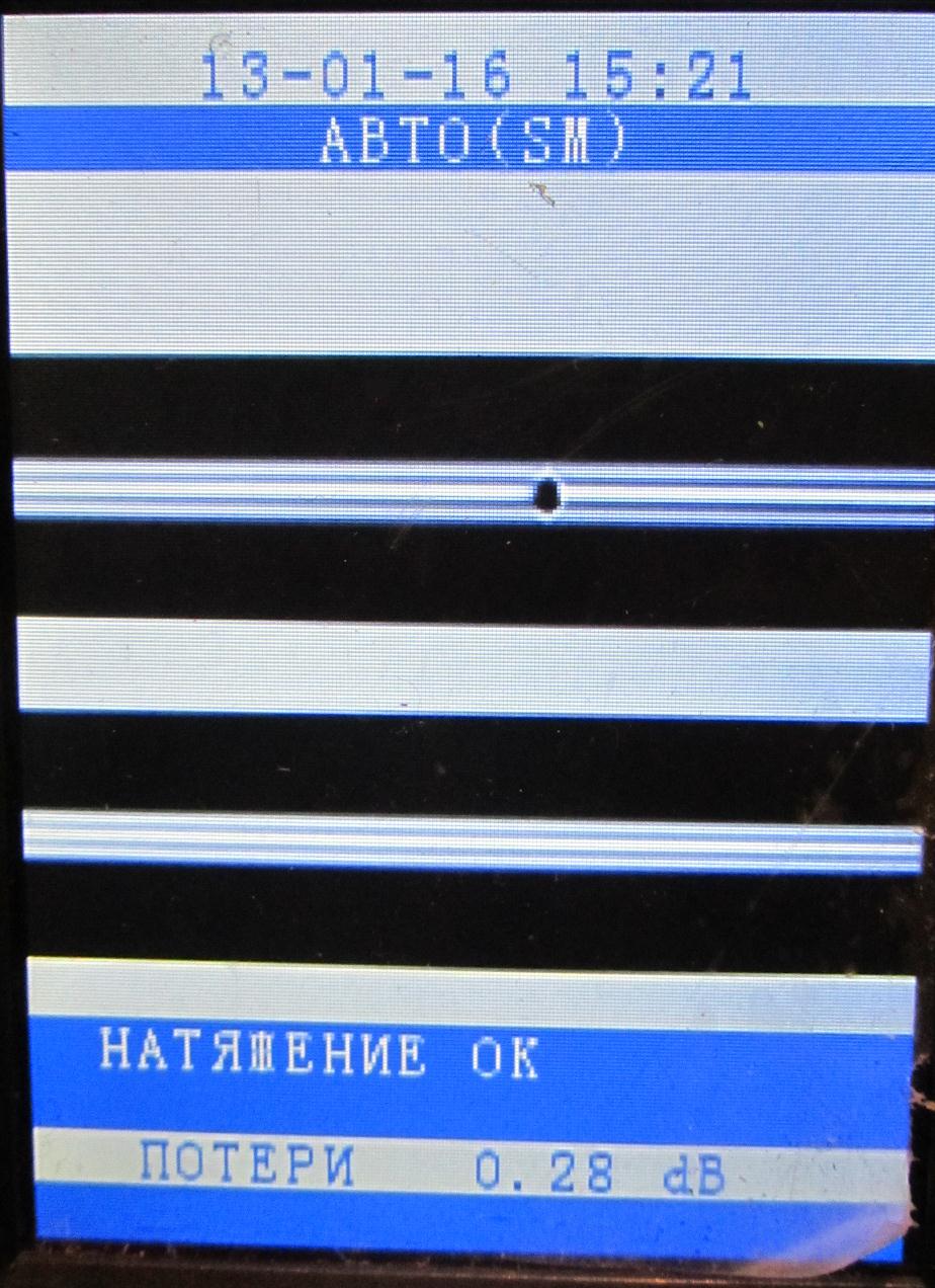
An example of normal welding. A small strip or divorces, as in the photo, are in principle undesirable, but statistically it almost does not affect the attenuation. If SM fiber is boiled with “displaced” fiber, then there are two characteristic points at the welding point.
Sometimes there is a need to weld an attenuator, that is, welding with some attenuation. Then, when choosing this mode, the welding machine intentionally shifts one of the fibers by several microns and the welding results in a bit of a curve. I didn’t cook such attenuators and can't tell you anything about it.
g) The welded fiber in the tie is carefully removed from the welding machine and the KDZS sleeve approaches at the welding point. Until KDZS not seated, the fiber is not protected and can be easily broken.
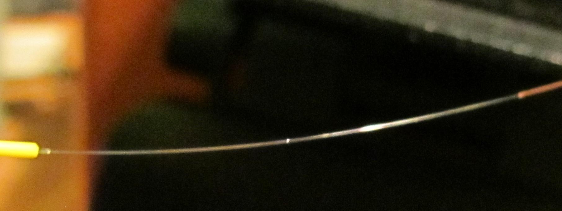
The welded fiber (macro). A point is visible in the place of welding; refracting light is normal.
After that, the fiber with the liner is laid in the in-oven in the welding machine so that the edges of the lacquer protective coating of both fibers enter the KDZS, that is, after shrinking the fiber there are no areas with bare unprotected glass. The liner should be set to the appropriate operating time of the stove (use preset modes for KDZS 40 or 60 mm).
Now welding always sits in KDZS. However, I saw the old technology, when in a cassette instead of a cradle for KDZS there was such a long plastic bath, there was poured brown translucent glue or compound and the welded fibers were neatly laid, drowning the spot of welding in this bath. After some time, the glue froze and the glass was protected. The disadvantages of this method are obvious - there is no access to a single fiber to pull the fibers through and see which color is soldered with, as a result, it is difficult to find the right pair of fibers, if something is needed to digest, and the installation process is more difficult.
g) The welded and seated fiber is removed from the oven and placed in the cooling tray for about a minute. Non-sharpened should not be laid in the cassette, since the plastic is still soft and the fiber inside the can be easily crushed by crushing the in the cradle of the cassette. By the way: if KDZS is not pulled out of the stove immediately after the timer ends, it can stick there. A common beginner's mistake: I forgot to immediately pull out KDZS, it stuck, but it was not completely frozen. The newcomer begins to pick it out with tweezers and through the soft plastic breaks the fiber ... And without noticing it puts the KDZS in the cassette. If KDZS is stuck in the stove, you can either pry it with something like a ruler, or pull the fibers tightly to the sides and pull it up, or wait until it cools, and touch it with tweezers - it will easily come off.
h) The welded cooled fiber (or the entire welded module at once) is placed in the cassette.
Laying fibers in a cassette
Laying can be done in different ways: either you first put KDZS in the cradle, and then put one and the second loop of fibers, or start with one of the loops of the fiber, reaching KDZS, lay KDZS and then lay the remaining length of the fiber. In any case, care should be taken not to damage the stacked and other fibers and to lay the fiber evenly. If the fibers before welding were not measured and trimmed, then after welding the fiber may lie in the cassette inaccurately or not at all. When laying it is very important to observe the bending radii, not to allow too much bending and squeezing of the fiber, since such bending will be a source of strong signal attenuation. If somewhere you make a mistake with measuring and the fibers do not fall normally, it is better to let them be glued to the tape with tape, than to be strained on guides with strong bends.
i) After the fibers are laid, you should sign and indicate on the cassette with arrows and curly brackets which fibers go where. You can also use arrows with inscriptions to show which cable you are going to, or stick the couplings on the cables with tags indicating the direction from the inside. Similar tags, only waterproof, it is necessary to mount and outside the coupling / cross on the cable, on these tags indicate where the cable goes, the code of the communication line, the owner, etc. according to the customer. It will also be good practice to throw a copy of the decoupling scheme into the clutch (although this is a controversial point: the one who gets into the clutch legally and so should have this scheme, and if someone digs into the clutch without a scheme, this is not normal).
j) After all the fibers are welded in accordance with the unwelding scheme and laid, you can (without forgetting to take a photo of the coupling, if the customer requires it, and throw a bag of silica gel into the coupling) to proceed to the assembly of the coupling and sealing. These operations are carried out in accordance with the assembly instructions for the coupling. If the cables are sealed with heat shrinkage, it is important to prevent overheating of the tube when shrinking them with an industrial dryer or a gas burner, since some heat shrinkable tubes tend to burst from local overheating. On some heat shrinkable tubes (Tyco electronics, for example), there is a green dot marking, which disappears when the area is warm enough. If the shrinking is still broken, then in order not to redo the work from scratch, you can seat a detachable heat shrinkable cuff, known as XAGA (if available).Such a cuff is a heat-shrinkable canvas with hot melt on one side and with "sides" at the edges.
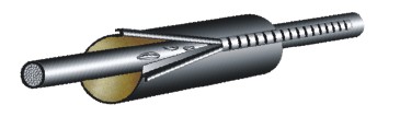
These cuffs come in different sizes. Some are suitable for sealing the cable entry in the coupling, others may embrace the entire coupling (if we have a coupling like MOG or MTOK A1).
Cutting a piece of cloth, wrapping it around the cable with the glue side inward, aligning the sides and pulling the lock over them, we get essentially ordinary heat shrinkage. We heat with a hairdryer or a burner - the glue melts, the cuff sits. But such a cuff is relatively expensive (about 2,000 rubles per 1.5 meters).
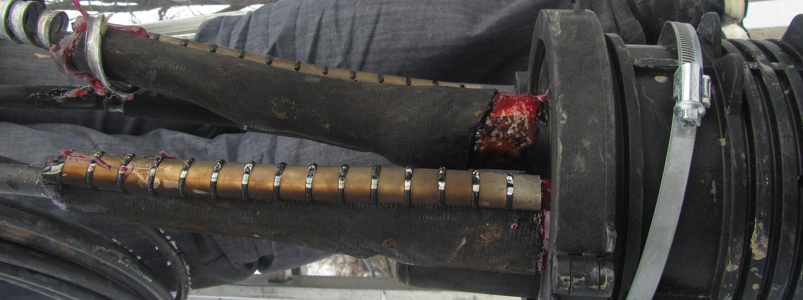
Two of the three cables included in the coupling (one of the optical ones - the bottom one and the ground wire in the metal hose - the top one) are sealed with a heat shrinkable cuff. Upper - a little careless: cuff half got off the pipe.
If the cables are sealed in a cold way, attention should be paid to the quality of adhesion of the sealant to the cable, to observe the requirements in the instructions (stripping the cable with emery paper, etc.). Coupling leakage is not allowed! Especially important is the quality of sealing for couplings installed in wet basements and wells, where full flooding is possible. You should also put a bag of silica gel (if included) in the clutch so that the silica gel absorbs moisture from the air inside the clutch.
The assembled and sealed coupling should be carefully, without breaking the cables, placed in its permanent place and fastened if necessary. If the coupling must be on the pole (support), then the cable reserve is wound on a large iron cross-guard, UPMK, which is fixed in advance to the pole with steel tape.
I will try to tell about fastening of cables and couplings in the next part.
Bonus
I recently bought myself a student-level microscope — Micromed C-11, with an optical zoom of up to 800x. Partly because I have long wanted such a toy. :) Partly because the topic about optics turned out to be interesting for readers and I decided that it would be interesting for you to look at the photographs of the fibers in a microscope.
One thing is professional photos from the Internet, and another is such hand-made photos. I don’t know for whom how, but for me at first there wasn’t welding the optics of that very “bridge” between the microworld and the macroworld, there was nothing to “hook on” to “touch” and look at the fibers. Yes, I already had the practice of soldering, yes, I knew the theory, but “to feel with my own hands”, to understand - this was not enough for me. I hope these photos will give you such a “bridge”.
Fix a webcam with a rubber band on the eyepiece of the microscope - a couple of trivia. :) For greater clarity, I took a series of photos, gradually changing the focus by raising the object table, and combined the series in A-PNG animation. Spread what happened. In the old Opera (which is on Presto) the animations work, it seems to work in Firefox, in IE 9 they don’t work, I don’t know about other browsers.
The well-chopped fibers look uninteresting: we see the refraction of light in a glass cylinder, and the concept of volume is lost, so I took the fibers, broken off with tweezers, while the volume of the fiber was clearly seen when changing the focus point.
Fiber in the outside light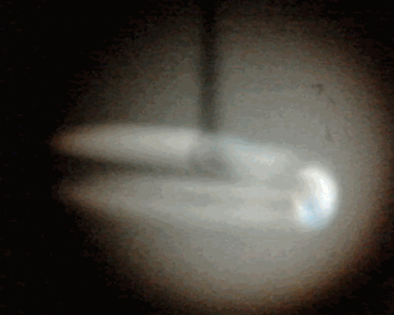
Fiber in transmitted light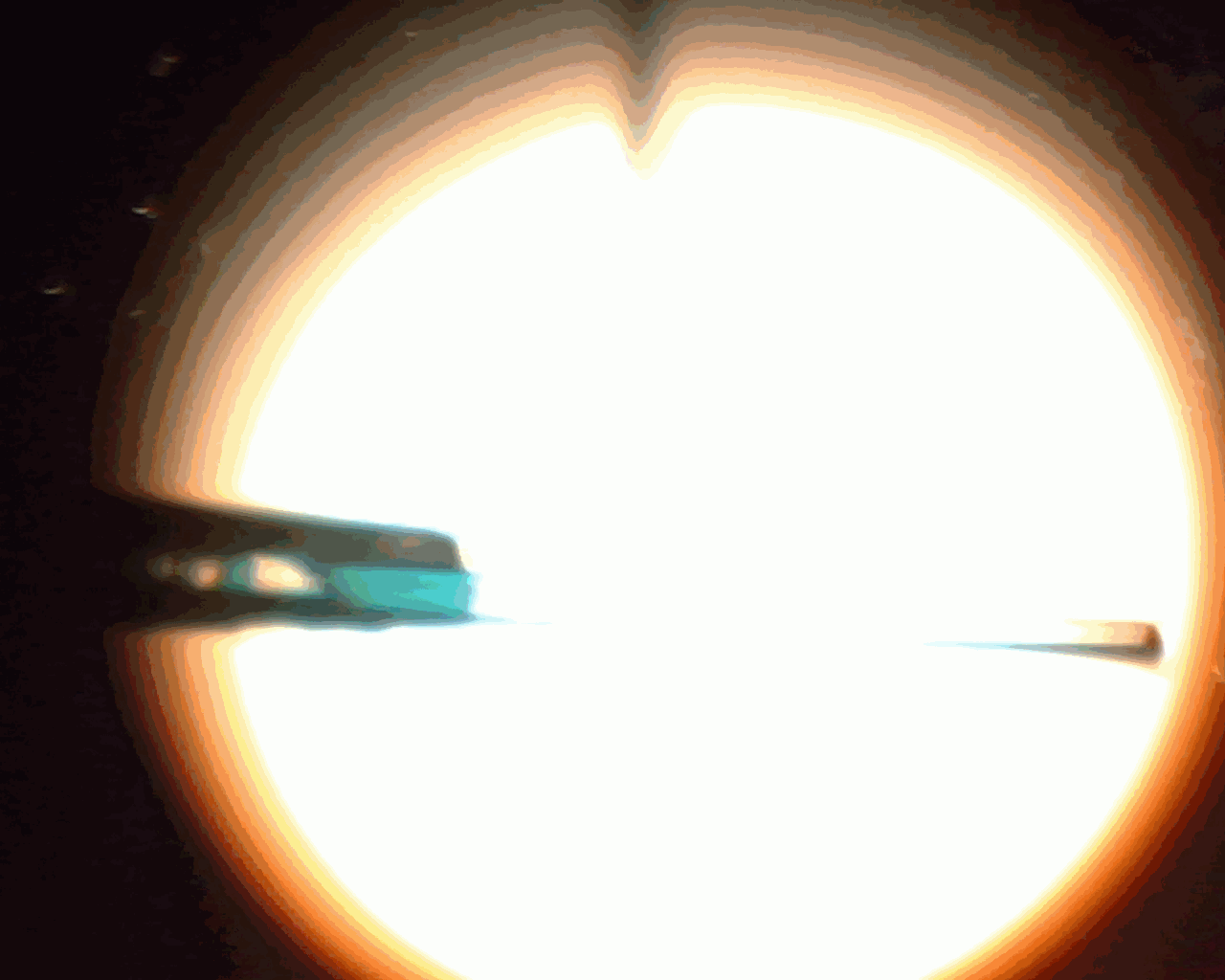
More fiber in transmitted light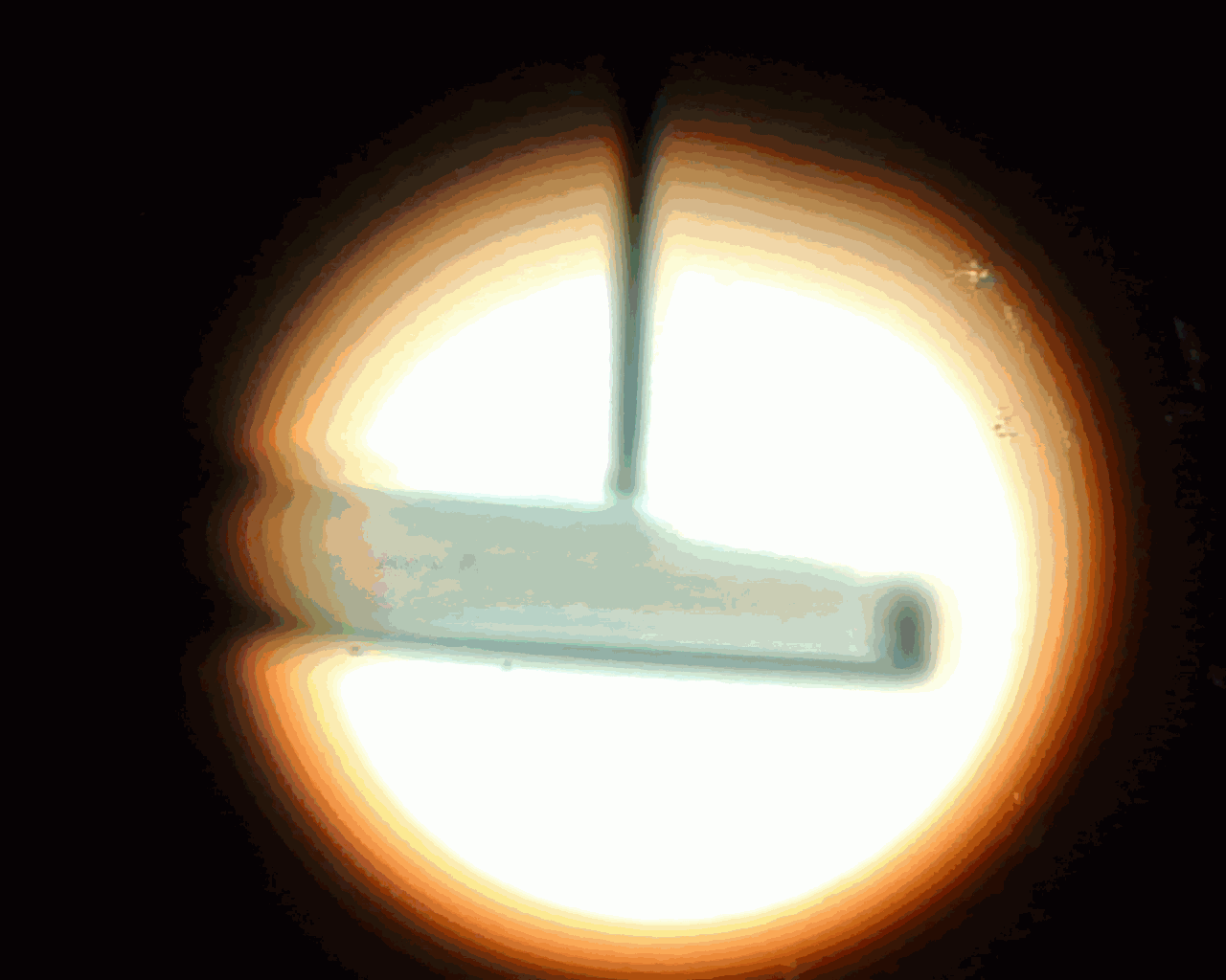
Again in transmitted light. Habrastoraj did not fit the limit, if the picture becomes broken - then I will correct
— , .
800
: 800 . . , , , , () . , 800 - — .
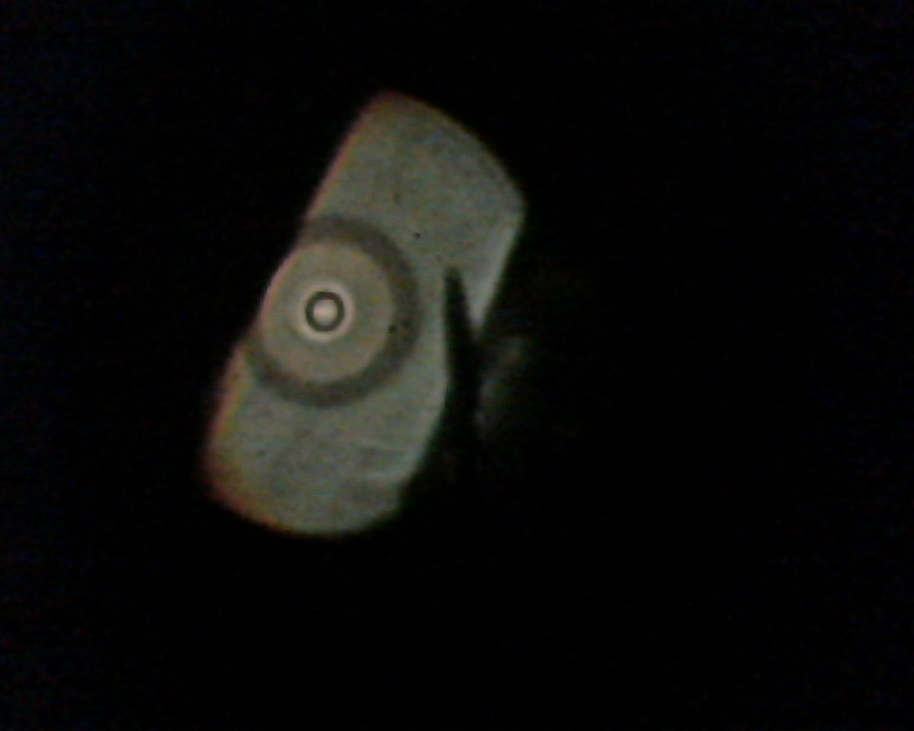
I must say, I myself do not fully understand what we see in this last photo. :) Single mode fiber. On the left or along the chord there is a bad chip, or on the side that is adjacent to the glass, the edge of the fiber is soiled and the light does not pass. On the right, a sharp object is a needle in the eyepiece. More to the right - definitely a bad chip on the chord (on the animation, when I change the focus, you can see how the focus zone walks along this part of the fiber). But where do alternating concentric circles come from - I don't know. :) The light obviously passes through the glass core and through the glass shell (they are equally transparent over the length of a couple of centimeters). In theory, we should see either a uniformly bright circle (taking into account the defects from dirt and cleavage described above), or a separate point in the center, or we should see something like what we would see if we looked at the light longmirror pipe from the inside.
At this point I finish the second part of my story. In the third part I will try to write about measurements on optics, about reflectometers, and also touch on the subject of cable fastening a bit. In addition, I want to show typical decoupling schemes and show how they are read. I also have a certain number of photos from workplaces, part of work (couplings, tent, table, hatches with cables, fixtures, etc.), and many of them are not directly related to optics (just landscapes from roofs, interlacing cables, basements with garbage, unknown to me racks with equipment in different LAZ and server, etc.). Perhaps I will issue them later as a separate post-addon.
Thanks for attention.
Source: https://habr.com/ru/post/195720/
All Articles