interop mode and IVR on Cisco MDS
Let me share some experience in the SAN context.
In one unknown organization there is a server in which the SAN network was implemented and successfully operates. There are two factories in the network, each factory had an HP AM869A 8/40 switch. As it turned out, these switches are the forty-port Brocade 5100 SAN switches, running Fabric OS. Several dozens of servers and a pair of data storage systems are connected to these factories. Without details, all this looks like this ... scary:
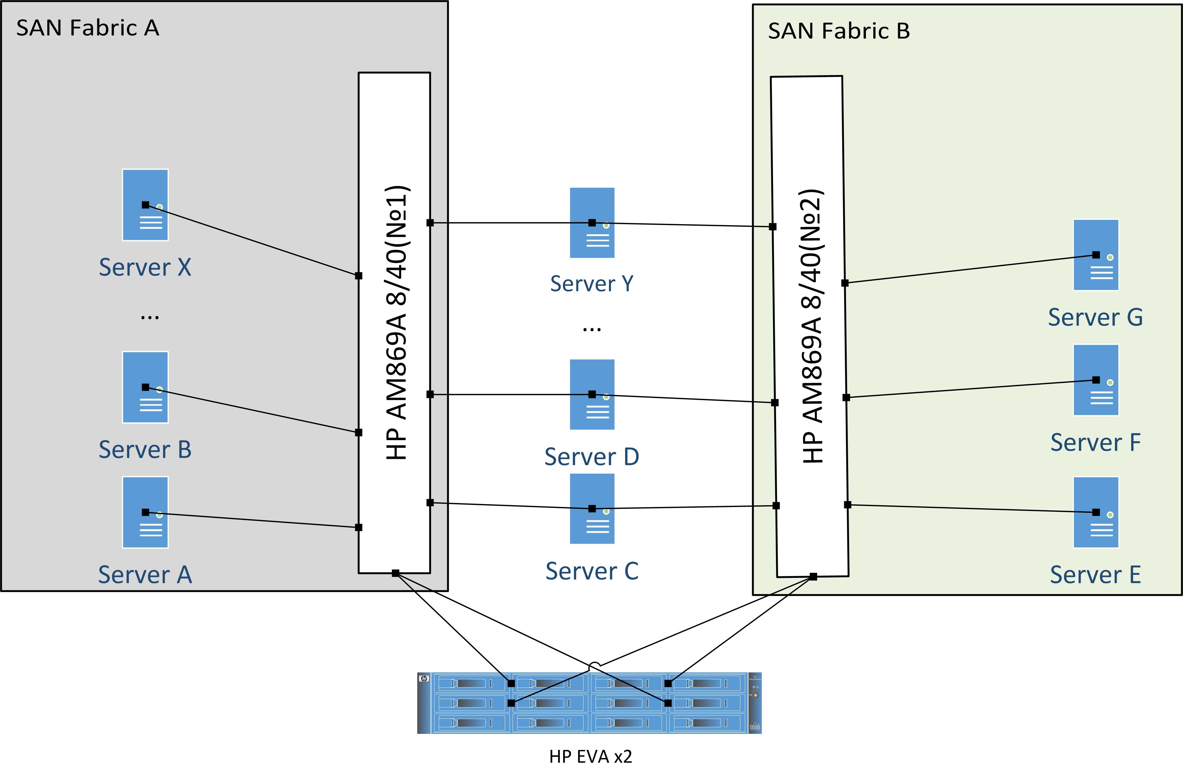
As you can see, in addition to the happy servers that are connected simultaneously to both factories, there are servers connected to the SAN network in an unreliable way, with only one link to one of the switches. Alas, that is - that is.
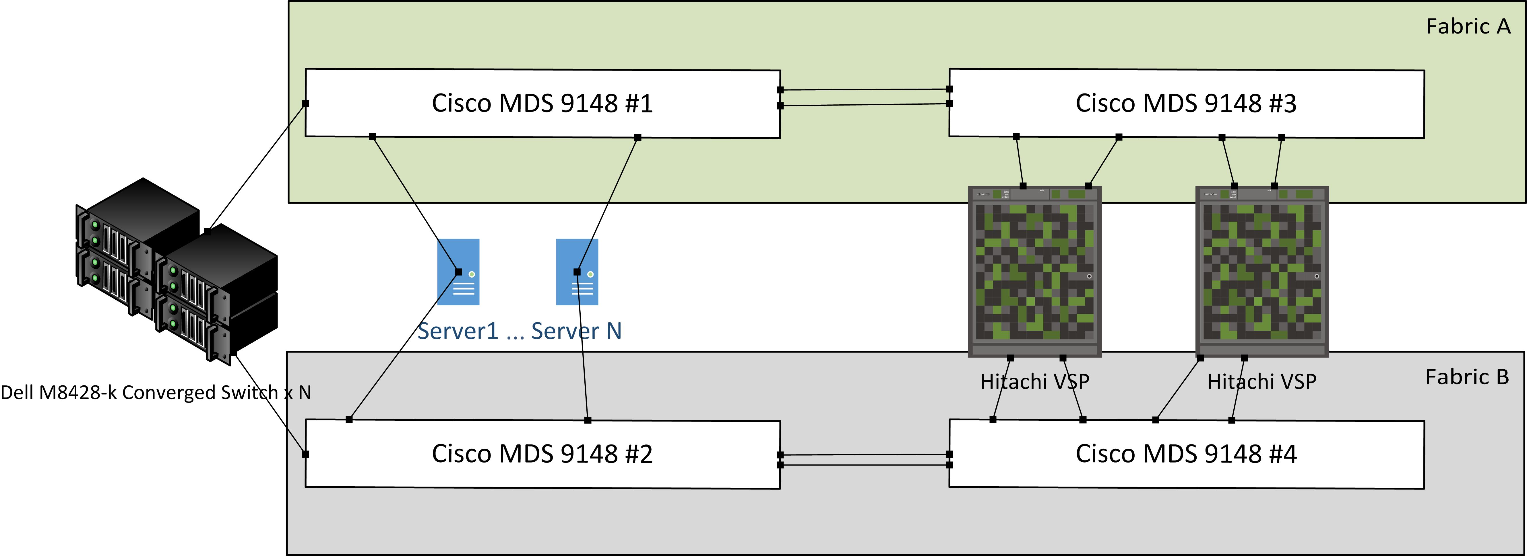
The organization developed and organized itself another server in the next building. In the new server there were a few more servers and much more storage systems. Cisco MDS 9148 is used as a switch, to which Dell M8428-k I / O modules are connected in AG mode (these modules are installed on a Dell M1000 baskets blade). Also, the Hitachi VSP rack servers and storage systems are connected to the MDS switches. A small sketch of the SAN network of the new server:
')
The task was set clearly. It is necessary to migrate a number of services from the old server to the new. Services running on virtual machines. Both servers use the VMware vSphere virtualization platform. In our case, the main stages of preparing the infrastructure for migration were:
What needs to be done to combine our factories with the old and the new server?
I think, first draw, what we want to get:

In the new server room, when setting up a zonning, VSAN 1 was used in both factories. In order that all manipulations when connecting the factories to MDS switches were not distributive, VSAN 2 was created, which will work in Interop mode with the HP switch. Next, we will talk about the union of the factory (MDS # 2 - # 4) and the factory (HP AM869A 8/40 No. 1). The merging of the other two factories will be carried out by analogy.
Most operations must be performed on a Cisco MDS 9148 # 4 switch.
Why do I need Inter VSAN Routing?
In order for us to create a zone for pWWN which are located in different VSANs, in our case this is the VSAN of the old and the new server. Let me remind you that our goal is the ability to interact nodes from two different factories.
Now, you can present LUs and connect them as stores, and at the same time the storage and server will be from different factories.
I hope the article will help someone or be interesting.
Please comment and ask questions, I will answer with pleasure.
Given:
In one unknown organization there is a server in which the SAN network was implemented and successfully operates. There are two factories in the network, each factory had an HP AM869A 8/40 switch. As it turned out, these switches are the forty-port Brocade 5100 SAN switches, running Fabric OS. Several dozens of servers and a pair of data storage systems are connected to these factories. Without details, all this looks like this ... scary:
As you can see, in addition to the happy servers that are connected simultaneously to both factories, there are servers connected to the SAN network in an unreliable way, with only one link to one of the switches. Alas, that is - that is.
The organization developed and organized itself another server in the next building. In the new server there were a few more servers and much more storage systems. Cisco MDS 9148 is used as a switch, to which Dell M8428-k I / O modules are connected in AG mode (these modules are installed on a Dell M1000 baskets blade). Also, the Hitachi VSP rack servers and storage systems are connected to the MDS switches. A small sketch of the SAN network of the new server:
')
Task
The task was set clearly. It is necessary to migrate a number of services from the old server to the new. Services running on virtual machines. Both servers use the VMware vSphere virtualization platform. In our case, the main stages of preparing the infrastructure for migration were:
- Combining the data network in order to connect the hosts of the old server from which services will move to the vCenter Server in the new server for the possibility of vMotion.
- Combining the SAN network so that the selected hosts of the old and the new server have a common storage and storage vMotion can be performed.
What needs to be done to combine our factories with the old and the new server?
I think, first draw, what we want to get:
In the new server room, when setting up a zonning, VSAN 1 was used in both factories. In order that all manipulations when connecting the factories to MDS switches were not distributive, VSAN 2 was created, which will work in Interop mode with the HP switch. Next, we will talk about the union of the factory (MDS # 2 - # 4) and the factory (HP AM869A 8/40 No. 1). The merging of the other two factories will be carried out by analogy.
Preparing and configuring interop mode
Most operations must be performed on a Cisco MDS 9148 # 4 switch.
- First, create a backup of the MDS # 4 configuration:
mds4# copy running-config ftp: Enter destination filename: [mds4-running-config] Enter hostname for the ftp server: 192.168.200.252 Enter username: admin Please log in with USER and PASS first. Password: Copy complete, now saving to disk (please wait)... mds4# - Back up HP # 1 switch configuration:
configupload -all -p ftp 192.168.200.252,ftp_user,,password - Next, you need to check that the NX-OS and Fabric OS versions are compatible, you can find out this information in the documentation, and you can see the OS version on MDS by the following command:
mds4# sh ver Cisco Nexus Operating System (NX-OS) Software TAC support: http://www.cisco.com/tac Documents: http://www.cisco.com/en/US/products/ps9372/tsd_products_support_series_home.html Copyright (c) 2002-2013, Cisco Systems, Inc. All rights reserved. The copyrights to certain works contained herein are owned by other third parties and are used and distributed under license. Some parts of this software are covered under the GNU Public License. A copy of the license is available at http://www.gnu.org/licenses/gpl.html. Software BIOS: version 1.0.19 loader: version N/A kickstart: version 5.2(8b) <u> system: version 5.2(8b)</u> BIOS compile time: 02/01/10 kickstart image file is: bootflash:///m9100-s3ek9-kickstart-mz.5.2.8b.bin kickstart compile time: 12/25/2020 12:00:00 [07/03/2013 10:16:59] system image file is: bootflash:///m9100-s3ek9-mz.5.2.8b.bin system compile time: 6/5/2013 15:00:00 [07/03/2013 10:48:15] Hardware cisco MDS 9148 FC (1 Slot) Chassis ("1/2/4/8 Gbps FC/Supervisor-3") Motorola, e500v2 with 1036300 kB of memory. Processor Board ID JAF1649ATAG Device name: mds4 bootflash: 1000944 kB Kernel uptime is 11 day(s), 20 hour(s), 5 minute(s), 5 second(s) Last reset at 100354 usecs after Tue Sep 17 07:16:43 2013 Reason: Reset due to upgrade System version: 5.0(1a) Service: mds4# - On HP:
FC-Switch1:FID128:admin> version Kernel: 2.6.14.2 <u>Fabric OS: v6.3.1a</u> Made on: Fri Feb 26 18:38:50 2010 Flash: Tue Dec 7 06:31:48 2010 BootProm: 1.0.9 - Now do not be lazy and read the release notes for our firmware versions. You can read on the manufacturer’s website that the cisco MDS 9148 supports IVR, but unfortunately in NX-OS 5.0 (1a) it’s impossible to enable it on our IVR platform. And so you have to upgrade to the latest stable version of NX-OS, for example 5.2 (8b). And help to update the command:
mds4# install all kickstart bootflash:///m9100-s3ek9-kickstart-mz.5.2.8b.bin system bootflash:///m9100-s3ek9-mz.5.2.8b.bin - After the upgrade, make sure that we have a license that includes an IVR. In our case, this is an Enterprise license:
mds4# sh license usage Feature Ins Lic Status Expiry Date Comments Count -------------------------------------------------------------------------------- FM_SERVER_PKG No - Unused - ENTERPRISE_PKG Yes - In use 13 Oct 2014 - PORT_ACTIVATION_PKG Yes 32 In use never - -------------------------------------------------------------------------------- - Great, the MDS switch is ready to configure. First, turn off the interfaces that physically connect MDS # 4 to HP # 1:
mds4# conf t Enter configuration commands, one per line. End with CNTL/Z. mds4(config)# int fc 1/3-4 mds4(config-if)# shutdown mds4(config)# - Next, create VSAN 2, add our interfaces to this VSAN, and enable interop mode 3:
mds4(config)# mds4(config)# vsan database mds4(config-vsan-db)# vsan 2 mds4(config-vsan-db)# vsan 2 interface fc 1/3 – 4 mds4(config-vsan-db)# vsan 2 interop 3 - Also, at a minimum, you must turn off Brocades Per VC Flow Control on the HP switch, since it does not support cisco MDS and ISL will not go up and you will see the following events:
2013 Sep 26 08:24:57 mds4 %PORT-5-IF_DOWN_ELP_FAILURE_ISOLATION_UNKNOWN_FLOW_CTL_PARAM: %$VSAN 2%$ Interface fc1/4 is down (Isolation due to ELP failure: invalid flow control param) 2013 Sep 26 08:24:57 mds4 %PORT-5-IF_DOWN_ELP_FAILURE_ISOLATION_UNKNOWN_FLOW_CTL_PARAM: %$VSAN 2%$ Interface fc1/3 is down (Isolation due to ELP failure: invalid flow control param) - Turning off Per VC Flow Control on the HP switch (ports 21-22):
portcfgislmode 21,1 portcfgislmode 22,1 - Everything, ports can be turned on and after a minute already check that they are in the UP state.
FC-Switch1:FID128:admin> switchshow switchName: FC-Switch1 switchType: 66.1 switchState: Online switchMode: Native switchRole: Subordinate switchDomain: 1 switchId: fffc01 switchWwn: 10:00:00:05:33:49:40:e4 zoning: ON (DC_ZONESET) switchBeacon: OFF FC Router: OFF Allow XISL Use: OFF LS Attributes: [FID: 128, Base Switch: No, Default Switch: Yes, Address Mode 0] Index Port Address Media Speed State Proto ============================================== 0 0 010f00 id N4 Online FC F-Port 50:00:1f:e1:50:21:c5:fc 1 1 010d00 id N4 Online FC F-Port 50:00:1f:e1:50:21:c6:0d 2 2 010b00 id N4 Online FC F-Port 50:00:1f:e1:50:21:c6:09 3 3 010900 id N4 Online FC F-Port 50:00:1f:e1:50:21:c5:f8 4 4 010e00 id N8 No_Light FC Disabled (Persistent) 5 5 010c00 id N8 No_Light FC Disabled (Persistent) 6 6 010a00 id N4 Online FC F-Port 10:00:00:05:33:26:d8:77 7 7 010800 id N4 Online FC F-Port 10:00:00:05:33:48:00:56 8 8 010700 id N4 Online FC F-Port 10:00:00:05:1e:fa:fb:eb 9 9 010500 id N4 Online FC F-Port 10:00:00:05:33:26:7c:67 10 10 010300 id N4 Online FC F-Port 50:00:1f:e1:50:21:c5:fe 11 11 010100 id N4 Online FC F-Port 10:00:00:05:1e:fa:fc:40 12 12 010600 id N4 Online FC F-Port 50:00:1f:e1:50:21:c5:fa 13 13 010400 id N4 Online FC F-Port 50:01:43:80:06:34:23:5e 14 14 010200 id N4 No_Light FC 15 15 010000 id N4 No_Light FC 16 16 012700 id N4 Online FC F-Port 50:06:0e:80:16:4e:97:61 17 17 012500 id N4 Online FC F-Port 50:06:0e:80:16:4e:97:60 18 18 012300 -- N8 No_Module FC 19 19 012100 -- N8 No_Module FC 20 20 012600 id N4 No_Light FC 21 21 012400 id N4 Online FC E-Port 20:02:54:7f:ee:c1:26:61 "mds4" 22 22 012200 id N4 Online FC E-Port 20:02:54:7f:ee:c1:26:61 "mds4" (upstream) 23 23 012000 id N4 Online FC F-Port 50:01:43:80:06:34:23:8c 24 24 011f00 -- N8 No_Module FC (No POD License) Disabled 25 25 011d00 -- N8 No_Module FC (No POD License) Disabled 26 26 011b00 -- N8 No_Module FC (No POD License) Disabled 27 27 011900 -- N8 No_Module FC (No POD License) Disabled 28 28 011e00 -- N8 No_Module FC (No POD License) Disabled 29 29 011c00 -- N8 No_Module FC (No POD License) Disabled 30 30 011a00 -- N8 No_Module FC (No POD License) Disabled 31 31 011800 -- N8 No_Module FC (No POD License) Disabled 32 32 011700 -- N8 No_Module FC (No POD License) Disabled 33 33 011500 -- N8 No_Module FC (No POD License) Disabled 34 34 011300 -- N8 No_Module FC (No POD License) Disabled 35 35 011100 -- N8 No_Module FC (No POD License) Disabled 36 36 011600 -- N8 No_Module FC (No POD License) Disabled 37 37 011400 -- N8 No_Module FC (No POD License) Disabled 38 38 011200 -- N8 No_Module FC (No POD License) Disabled 39 39 011000 -- N8 No_Module FC (No POD License) Disabled FC-Switch1:FID128:admin> - We check that everything is in order with zoning:
FC-Switch1:FID128:admin> alishow
IVR setup
Why do I need Inter VSAN Routing?
In order for us to create a zone for pWWN which are located in different VSANs, in our case this is the VSAN of the old and the new server. Let me remind you that our goal is the ability to interact nodes from two different factories.
- Turn on IVR on the switch, and just in case ivr nat, turn on ivr distribution and automatic definition of IVR topology:
mds4(config)# feature ivr mds4(config)# ivr nat mds4(config)# ivr distribute mds4(config)# ivr vsan-topology auto fabric is now locked for configuration. Please 'commit' configuration when done. - Now, after any changes related to IVR, it is necessary to apply the changes, and then to check their success:
mds4(config)# ivr commit commit initiated. check ivr status mds4(config)# sh ivr session status Last Action Time Stamp : Sun Sep 29 06:06:01 2013 Last Action : Commit Last Action Result : Success Last Action Failure Reason : none mds4(config)# - Then everything is very simple, it is necessary to determine those pWWN with our VSANs that should interact. Suppose for the test I want to allow interaction between one of the repositories in the new server and the server in the old server.
Storage port addresses:pwwn 50:06:0e:80:16:7b:d8:01 pwwn 50:06:0e:80:16:7b:d8:61 pwwn 50:06:0e:80:16:7b:d8:21 pwwn 50:06:0e:80:16:7b:d8:41 pwwn 50:06:0e:80:16:7b:d8:11 pwwn 50:06:0e:80:16:7b:d8:31 pwwn 50:06:0e:80:16:7b:d8:51 pwwn 50:06:0e:80:16:7b:d8:71 - and server address:
pwwn 50:01:43:80:06:34:23:8c - Let's try to create an IVR zone:
ivr zone name Test_VSP2_ServerX member pwwn 50:01:43:80:06:34:23:8c vsan 2 member pwwn 50:06:0e:80:16:7b:d8:01 vsan 1 member pwwn 50:06:0e:80:16:7b:d8:61 vsan 1 member pwwn 50:06:0e:80:16:7b:d8:21 vsan 1 member pwwn 50:06:0e:80:16:7b:d8:41 vsan 1 member pwwn 50:06:0e:80:16:7b:d8:11 vsan 1 member pwwn 50:06:0e:80:16:7b:d8:31 vsan 1 member pwwn 50:06:0e:80:16:7b:d8:51 vsan 1 member pwwn 50:06:0e:80:16:7b:d8:71 vsan 1 - Next, create an IVR zoneset, add our zone there and activate it:
ivr zoneset name INTERDCSET member Test_VSP2_ServerX ivr zoneset activate name INTERDCSET force - But do not forget to apply the changes:
ivr commit - You can see the logs:
mds4# sh logging last 15 2013 Sep 26 10:37:36 mds4 %IVR-5-IVZS_WAITING_FOR_LOWEST_SWWN: Waiting for lowest switch WWN Inter-VSAN enabled switch in VSAN 1 2013 Sep 26 10:37:38 mds4 %IVR-5-IVZ_ACTIVATED_VSAN: Inter-VSAN zoneset INTERDCSET activated in VSAN 2 2013 Sep 26 10:37:51 mds4 %IVR-5-IVZS_WAITING_FOR_LOWEST_SWWN: Waiting for lowest switch WWN Inter-VSAN enabled switch in VSAN 1 2013 Sep 26 10:38:06 mds4 %IVR-5-IVZ_ACTIVATED_VSAN: Inter-VSAN zoneset INTERDCSET activated in VSAN 1 2013 Sep 26 10:38:06 mds4 %IVR-5-IVZ_ACTIVATED: Inter-VSAN zoneset INTERDCSET activated - You will also see that zones with the suffix IVRZ appeared in the zoneset for both VSANs:
mds4# sh zoneset brief active vsan 2 zoneset name DC_ZONESET vsan 2 zone EVA_serv1 output omitted… zone IVRZ_Test_VSP2_ServerX mds4# mds4# sh zoneset brief active vsan 1 zoneset name Fabric_B vsan 1 zone dell_tape_libr_drive2and1_pA_dell510_10_p0 zone VSP1_1A_dell915_3_p1 output omitted… zone IVRZ_Test_VSP2_ServerX mds4#
Now, you can present LUs and connect them as stores, and at the same time the storage and server will be from different factories.
I hope the article will help someone or be interesting.
Please comment and ask questions, I will answer with pleasure.
Source: https://habr.com/ru/post/195648/
All Articles