Robot-car team AURORA on “Robokross-2013”

Hi, Habr!
It is becoming a tradition to publish team reports after performing at RoboCross competitions.
Last season there were reports from the NAMT and MobRob teams , and now, I would like to tell you about the work of our team.
I will talk about how we did the robot, and why we did it that way. I hope it will be interesting to members of other teams, or just interested in similar subjects.
My name is Vladimir, I am a graduate student, a member of the Autonomous Robots RadioUniversity (AURORA) Ryazan team. My main interests are artificial intelligence, a team activity is software development. The team represents the student design bureau (SKB) of our uni.
Task description
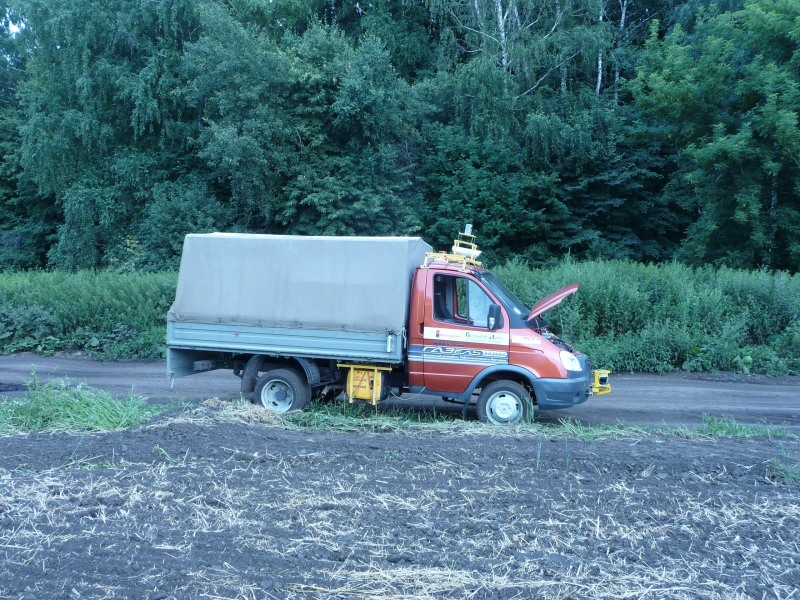
Competitions “Robokross-2013” were held at the avtogonigone “Birch Forest” of the GAZ plant (Nizhny Novgorod) from July 17 to 20. Under the race, a section of the “sports circle” was allocated, about 100m long.
The essence of the task: the robot-car autonomously moves behind a man at a slow speed (about 5-7 km / h), and remembers the route. Then it turns around (in manual or offline mode) and, at the command of the operator, must autonomously return to the starting point. At the same time, on the way back, the judges set several obstacles on the road, which were not there when moving forward (plastic barrels).
The task is similar to the behavior of a mule - if he is brought into the mountains and released, he will find the way and return to the herd. The task was taken by analogy with one of the tasks ELROB-2012 (European competition of robot-cars).
When performing the task, the time spent on the movement from start to finish, as well as the number of knocked down obstacles, was estimated. The winner could only be a robot with fully autonomous control.
Despite the apparent simplicity, only a few teams coped with the task (successfully reached the finish line).
')
Description of mechanics and electronics
Several people work on the robot car. About three each - above the mechanics, electronics, and top-level programming. There are no clear posts - everyone should be able to understand several areas. The team worked on the creation of the robot for 2 months, working even on Sundays, and leaving the laboratory not earlier than 21.00.
Mechanics and electronics are the “muscles” and “peripheral nervous system” of the robot.
Mechanics
Mechanics are a set of actuators that drive a vehicle’s controls. When developing mechanics, the main requirement was to make an easily removable structure, so that you can quickly disassemble everything, and the car turned into a regular Gazelle.
The actuator unit that controls the gas / brake / clutch pedals and the gear selector is located under the driver’s seat on the seat mounting. Those. you can sit in the driver's seat (legs, however, is not very comfortable).
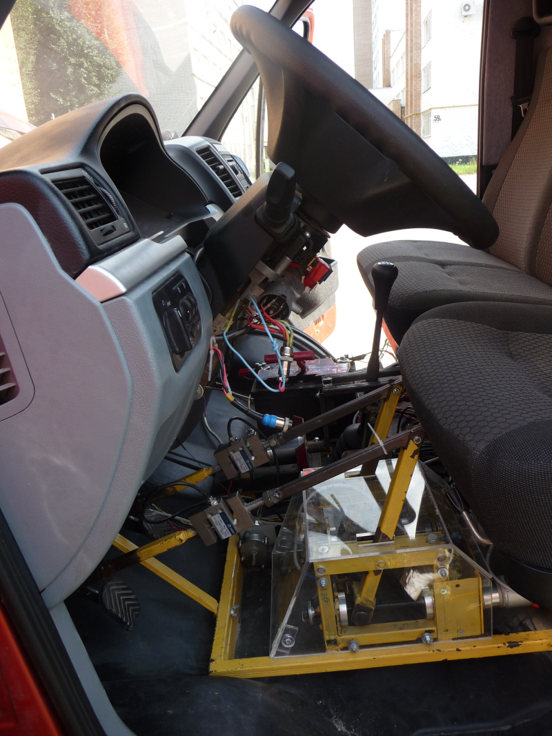
Pedal unit
To connect the pedals used special levers, brackets, which are thrown on the pedals.
The wheel is set in motion by a motor that is connected through a chain to the steering gimbal (it was necessary to cut it and weld the gear, but this was done several years ago, so it was decided to leave it as it is).
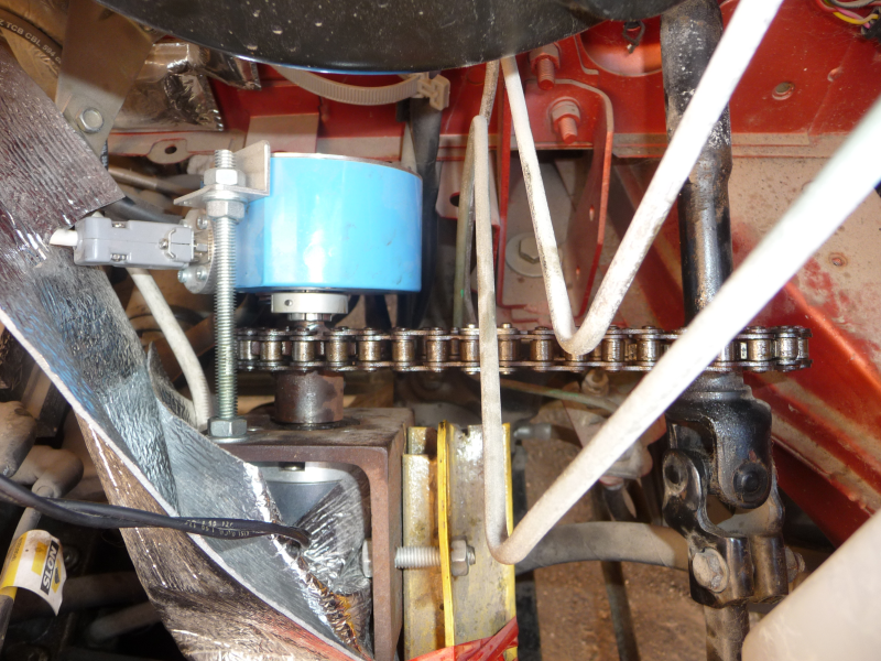
Here the blue encoder on the same shaft with the motor is connected by a chain with the steering cardan (under the hood)
The ignition circuit is in two modes - when the car starts with a key (as usual), or it is connected via a relay and safety buttons so that you can start autonomously. Once we paid for this switching method, having forgotten to switch the mode - the car cannot be stopped in case of loss of control. But everything worked out.
Electronics
We use our own electronics for all of our robotic projects. And develop it from scratch. It seems you can buy Arduino, NI RIO, and some kind of motor controller, or something like that, it will turn out cheaper and faster. But there are a few but. Learning how to tweak something, or even more to improve it, can only be known how it all works. What is called a "feel" system. And to do this, you can only try to repeat it yourself, taking steps, figuring out what, why, and how. We have already had development experience, and for several years we have developed this area. And if in the first seasons we lagged behind the teams that use ready-made solutions, now we have experienced circuitry developers, well-established solutions and can fully adapt them to any needs.
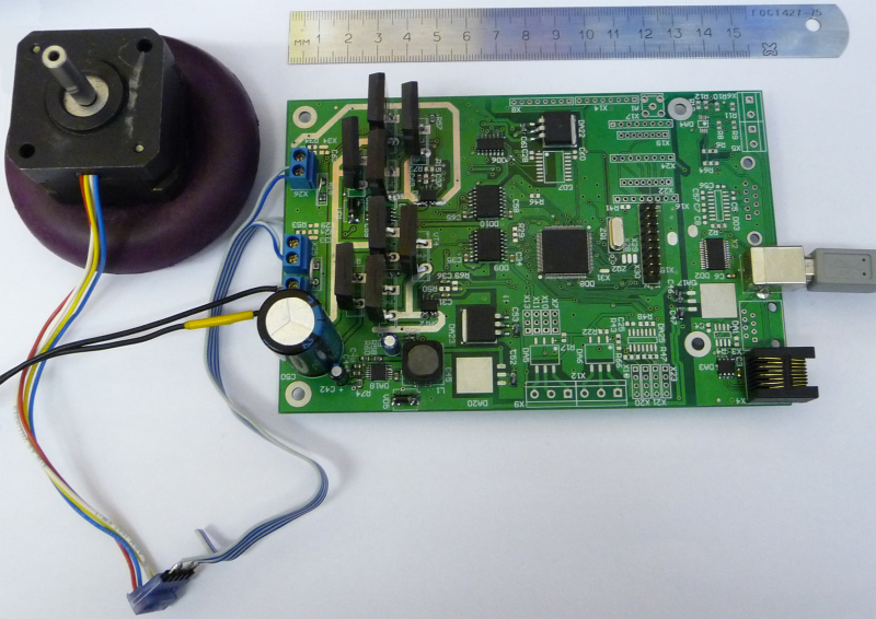
Motor control board
Electronics and “low level” software are represented entirely by our solution - motor control cards . The firmware of each board is adapted for a specific task - clutch / brake or steering control. The corresponding algorithm is “wired up” in each. Feedback on absolute and relative encoders, as well as limit switches and engine speed.
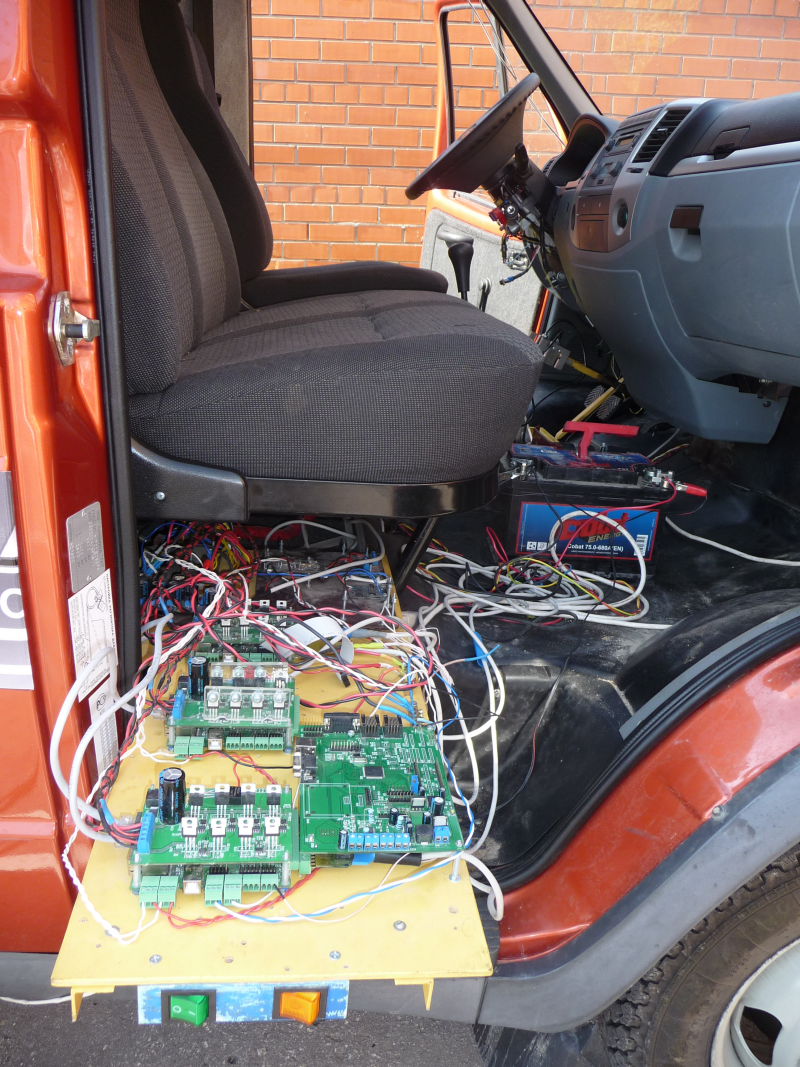
The control boards are mounted on a retractable rack, and can be easily removed under the driver's seat of the Gazelle.
Additionally, the boards are equipped with “dry contacts” or relays, for programmatically switching on the ignition or light / sound alarm and switching on other actuators.
Interesting is the problem of starting the car, which is especially evident when driving uphill. It is necessary to monitor the engine speed and play the clutch / gas pedals so that the car does not stall. The driver performs it on an intuitive level, but it is not very easy to do it automatically.
The “low level” controller (using LPC NXP controllers with ARM7 architecture) controls the actuators based on the commands received from the “high level” program (i386 arch). Communication interface - RS232, normal COM-port. A control command is a set of parameters {steering angle, speed, brake, auxiliary relays}. The controller also sends the “top level” the current engine speed and some other parameters necessary for making decisions.
Description of the program architecture and algorithms
Finally, I moved to the part I was working on directly.
Many years ago, when everything was just beginning, all universities bought NI controllers for their teams. We did not have the funds for them at that time, so it was decided to make the “brains” of the robot on i386 architecture, i.e. normal laptop or desktop pc. But I would hardly have gained development experience under Linux and embedded-linux, as well as well-known OpenCV image processing libraries, etc. (I do not want to offend NI, we also recently appeared RIO - a curious thing).
Sensor Kit
A set of sensors used for these competitions:
- encoders for steering and propeller shaft positioning (for positioning)
- weatherproof IP camera (for tag detection)
- SICK Line Laser Scanner (for building a cross-country map)
- orientation board (gyros + accelerometers) (for positioning)
- GPS receiver (for positioning)
Sensors are connected to the PC via RS232 and Ethernet.
To handle the sensory data in the back of the Gazelle, an ordinary PC is installed. The computer is powered by a gasoline generator, mounted outside under the body (symmetrically with the gas tank, on the opposite side).
Used libraries
The operating system we use is Ubuntu, the development environment is QtCreator, the language is C ++, the library for gui is Qt, the acquisition and processing of images is OpenCV, the processing of laser scanner data is PCL, and also the Boost for working with files and the network. The result was a cross-platform solution. However, we still use Ubuntu, since the system is more predictable, the antivirus or file indexing does not accidentally start working in the background, slowing down all other processes ... Yes, and the overall performance is slightly higher.
Following the label
The task of the competition involves the implementation of 2 elements - following the label and following the route. Therefore, the program provided for two main modes of operation - for each element of the task, respectively.
In the mode of following the label, the general algorithm of the program is extremely simple - you need to move behind the label and remember the points of the route until the operator removes the label. The position of the steering wheel during movement is proportional to the position of the mark relative to the center of the frame.
If the tag is lost, the robot beeps and after a while (0.5 seconds) starts to slow down. This is done for security reasons, and logically it turns out quite well - when it is necessary for the car to stop, the label is removed (turned over by the back side).
A label is a sign located on a pole (also for safety). We used a pink circle with a black contour, as this color is rarely found in nature.

Check the algorithm for the movement behind the label
To search for tags, several libraries were tried, but in the end a custom solution was implemented - search by form + color analysis. This allows rejection of traffic signs and other circular objects that differ in color from the mark.
Demonstration of the tag search algorithm
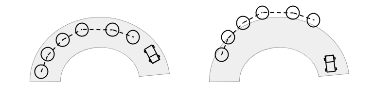
The coordinates of the route are described by the list {GPS point, orientation (angle of rotation), radius (when hit at which this point is considered to be reached)}. At the end of the movement, the points are reversed and the route is saved.
Return to the starting point
At the stopping point, the operator removes the mark - and the robot stops. The problem is that he must somehow turn around. There were no restrictions on the way the robot turned around in the competition rules, so we chose the manual method - when the operator himself turns the car. The trajectory planning algorithm, hypothetically, could have planned a reversal, but we decided to spend time debugging more necessary functions at that time.
We immediately abandoned the “simple algorithms” of the type “If the barrel on the left is the steering wheel to the right, if the target on the right is the steering wheel to the right,” etc. I call it the "cattle method." Obviously, with the appearance of a second barrel, or additional conditions, cattle-methods are not consistent.
The autonomous movement algorithm can be represented as a consistent solution of the following questions:

Where I am?
In order to decide where the robot should go, what amendment to make to the trajectory, the robot must know where it is, i.e. answer the question “where am I?”. For this purpose, you cannot use only data from a GPS receiver, since the GPS error is tens of meters, not to mention the movement near buildings or in a tunnel. Moreover, if you stand in the field with a GPS receiver and remove the coordinates, then after a certain, having come to the same place, the coordinates will be significantly different. Also, the problem is the low rate of issuance of coordinates - from 1 to 5 times per second, which is not enough to control the car even at a speed of 5 km / h - the system simply will not have time to react to the situation, and the robot will move like a drunk driver, or overshoot will occur.
The way out of this situation is the use of several sensors of different nature, based on different physical phenomena. In our robot, in addition to GPS, we use wheel encoders - determining the linear and angular velocity of the vehicle based on the data on how much the propeller shaft spins, and how the steering wheel was oriented. As an additional channel, an orientation determination board based on gyroscopes, accelerometers and a magnetic compass is also used.
Each sensor has a different rate of information output (for example, encoders - 70Hz, orientation board - 10 Hz). They are also characterized by a different nature of errors. Due to the inaccuracy of determining the size of the wheels and the length of the wheelbase of the car, navigation, based only on encoders, is characteristic of the accumulation of errors with time. Gyroscopes are subject to thermal drift and vibration of the car body. The compass reacts strongly to large metal objects (bridges, arches, etc.), respectively, the use of each sensor separately is also impossible.
To combine the indications of various sensors, various techniques are used, we chose to use a variety of non-linear Kalman filter - Unscented Kalman Filter. On the fingers, the principle of operation can be explained as follows: on the basis of the model of vehicle movement (it cannot teleport or move sideways), the readings of each sensor are predicted. Then, the predicted value is compared with the actual (measured) and each sensor, in accordance with the probability that it shows the truth, put its weight (the closer to the predicted, the greater the confidence). Based on the weights obtained, an estimate of the current position and orientation of the vehicle is formed.
Using D-GPS, of course, would make the task easier, but it requires a subscription fee - you can not buy and forget (consumables are very problematic).
Nevertheless, the obtained position estimate is acceptable for control - there are no marked jumps in coordinates, therefore, the trajectory control regulator behaves predictably.
Where to go?
When the position of the robot is known, it can be determined where the target point is relative to the robot. The problem at this stage is that, as noted earlier, GPS is subject to slow drift - the coordinates “float” during the day. This can be explained by the inhomogeneities of the atmosphere, clouds, clouds - all of this affects the signal transit time.
This is manifested as follows.
GPS drift
As the robot waits at the pivot point, its current position begins to “float” to the side. Those. if we launch it using the GPS-only method, it will move at a certain offset relative to the original trajectory, and the sensors will show that we are moving normally - they don’t know that all coordinates have moved. This will lead to the fact that the robot will go along the side (well, or on the tree, or concrete blocks). So, of course, no good.
The solution to this problem is to use road position data when planning a path. It is convenient to present this data in the form of a two-dimensional image - a cross-country map. In fact, this picture is a top view, where the car is in the center, and passable areas are marked with one color (green), and impassable with another (white).
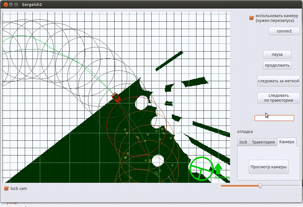
The figure shows a real cross-country map during test runs at the stadium.
Competition conditions imply a road enclosed by concrete blocks and high vegetation - bushes and trees. Therefore, it was decided to use only a linear laser scanner to obtain information about the obstacles that we fixed on the bumper of the car (see the first photo).
The principle of operation of the laser scanner is similar to a laser range finder, only the more complex optical system rotates continuously, providing a viewing angle of 180 degrees with an angular resolution of 0.5 degrees and a maximum range of 80 meters with a measurement accuracy of 2 cm. These parameters were enough for these competitions, and installing it at a certain height allowed us to see all possible obstacles on the track and the contour of the road.
The scanner returns an array of ranges, which is then filtered from single attacks (from grass or just noise), leaving obstacles with an angular width of at least 2 degrees. Then the array is drawn on the terrain map in polar coordinates relative to the center. Before each update, the terrain map is filled with impassable color, and only passable areas are drawn on it. This eliminates the algorithm for selecting a target point from the temptation to choose a point beyond the scanner's scope (in the shadow of concrete blocks or a fence). If this happened, the trajectory planning algorithm could not build it, since the target point is not reachable.
It is also important that the laser scanner is rigidly attached to the body. As a consequence, the patency map is constructed in local coordinates, i.e. we can not be mistaken with the location of the road in space.
So, we have a map of the terrain, the current position of the robot and the current point of the route to be reached. This is where the target point selection algorithm comes into play. It combines these data to obtain a valid (correct) target point to which the car can be guaranteed to reach.
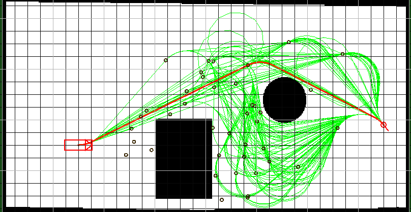
The principle of its operation is quite simple - a randomized selection of a set of points on the terrain map, next to the ideal target. Then the point nearest to the target is selected. The geometrical dimensions of the car are also taken into account - there must be free space around a point so that movement in the chosen area is safe. If the original target goes beyond the size of the permeability map, then the point shifts the distance Rmax (in our case, the map size is 40 * 40 meters, Rmax = 15m) so that it lies on the map, and then the search is performed.
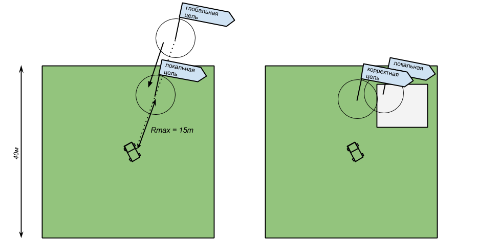
Schematic image of the cross-country map The white square symbolizes an impassable area.
How to go?
At the moment, the management task is reduced to the fact that we need to get from the center of the cross-country map to the target point. Again, the problem is that the classic shortest path search algorithms (A *, etc.) do not work here. Why?
Firstly, the space in which the robot-car moves is continuous. The coordinates (x, y) are real numbers. Classical algorithms are designed for discrete state space. Here, the set of transitions is infinite, and they will not work out.
Secondly, the car is a nonholonomic system. This means that the car cannot instantly change its position or orientation in space. Moreover, his next position is rather “rigidly” connected with the previous one - the restriction on the derivative of speed, the inability to instantly stop or change the direction of motion. Therefore, even if we construct the shortest path using a discrete algorithm (for example, rounding the coordinates to integers), then it will not be possible to drive along such a trajectory.
From all this it follows that it is not possible to obtain the shortest trajectory by the search method. In this case, we can only talk about the “near-optimal” trajectory. Such a trajectory is not the shortest. It is more important for us that the robot at the end point of the trajectory has the required orientation - if the robot arrives at the intermediate vertex perpendicular to the road - this will end badly. (Although in the background it is still important that the robot loop as little as possible).

You can come to the same point in different ways.
Various algorithms are used to find the path in the continuous state space. One of the most popular are the Rapidly exploring Random Tree (RRT) species. When the RRT works, the enumeration of all possible states is not performed. Instead, the entire space (in the general case) of states is covered by uniformly distributed vertices, which are then used as reference points for constructing the decision tree.
However, in its pure form, the RRT is not suitable for planning the trajectory of the car, since, again, it does not take into account the kinematic constraints. Therefore, in our work we used the algorithm proposed by Kuwata, Y and others [1].
The general idea remains the same as in the RRT. On the way of the car, N intermediate states are randomly selected.

Black circles indicate intermediate states. Red circle - the purpose and orientation of the car in it
Then a tree of trajectories is built from the source vertex. The process of checking the reachability of neighboring points is modified according to the model of movement of the car.
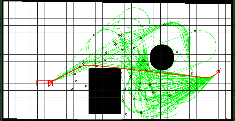
Demonstration of the trajectory planning algorithm. Depending on the orientation of the target, the resulting trajectory will pass in different ways.
When the limit of iterations is exhausted (the algorithm must have time to work in real time - the machine is moving!), Or the number of branches that have reached the target exceeds the threshold M, then the shortest path from the many available is selected.
The resulting trajectory is a set of Dubin's trajectories (Dubins path) - a set of segments and arcs of a certain minimum turning radius of the car. This kind of trajectories was designed specifically to represent the movement of the car and is the shortest path for movement from a point (x, y, theta) to (x ', y', theta '), taking into account the initial and final orientation.
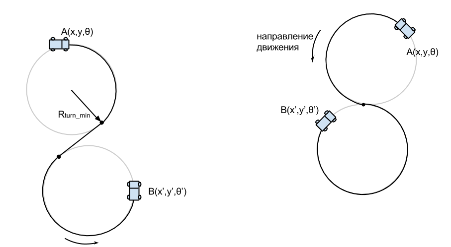
An example of Dyubins paths
The difficulty with the implementation of this algorithm lies in the fact that the method itself is computationally expensive (in fact it is a brute force). It was necessary to seriously optimize his work. The trajectory must be updated periodically to respond to changes in road conditions. Due to the presence of intermediate peaks, the maneuvers of the car were quite complicated (in a good way).
The trajectory is sent to the execution of the motion controller, which controls the steering and speed. The controller algorithm is taken similar to that proposed in [1].
I would also like to note that this algorithm is a “scheduling algorithm for the general case”. Those. when a priori information about the form of the road and obstacles is not known (traffic in the parking lot, in garages, traffic congestion). It is computationally complex, but it can generate complex trajectories. When driving on the highway, difficult maneuvers are not desirable, are not optimal, and even dangerous. Therefore, there are “lightweight” traffic planners focused on planning when driving only in a traffic flow (we have not yet implemented it).
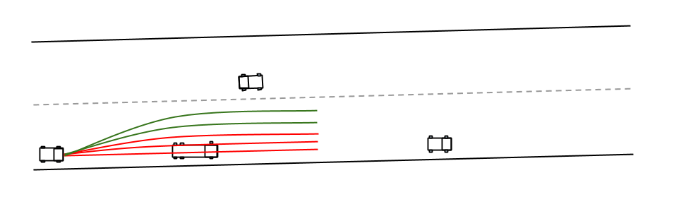
Highway Traffic Planner
Program mode switching
We didn’t think about the way of switching the program modes. In a hurry, we had to mount the Gozeli (we call a robot) outside the board with a small keyboard block with numbers - the right combination of numbers determined what the robot would do next:

Keyboard for switching the program mode (inside the jar). Next memo operator - so as not to forget
In general, with the choice of mode, we did not work very well. Since in order to deploy Gozel it was necessary to release the pedals, and for this to happen, the program must “release” them. As a result, you had to enter a lot of intermediate commands on the keyboard. In a nervous environment, they are easily confused. It is also curious that turning the car took more time than autonomous driving in both directions.
Common architecture
Based on the algorithms described above, you can make the following pattern of interaction between program components:

Debugging
Debugging is the most important stage in the development of any software product, especially when it comes to software for controlling a robot car. But here there are some difficulties.
The cost of the error is a damaged car or infrastructure. Not to mention the danger to team members. Here bugs are expensive.
Also an important problem is the cost of testing. Debugging the entire system is desirable in a deserted place, away from objects that can be damaged if something goes wrong. For this you need to deliver a car there. And the cost of towing services is not compensated by anything.
Therefore, we created a simulator on which it was possible to check the overall operation of the algorithm and the logic of the assignment. Irrlicht was used as a graphic engine, and BulletPhysics physical.The robot software is a client-server interaction, where the server is a software interface between the algorithm (client) and the hardware of the robot (sensors, actuators). It turned out that in order to switch from the simulator to a real robot, it was necessary to specify a different ip address in the client - very conveniently - no code modifications.
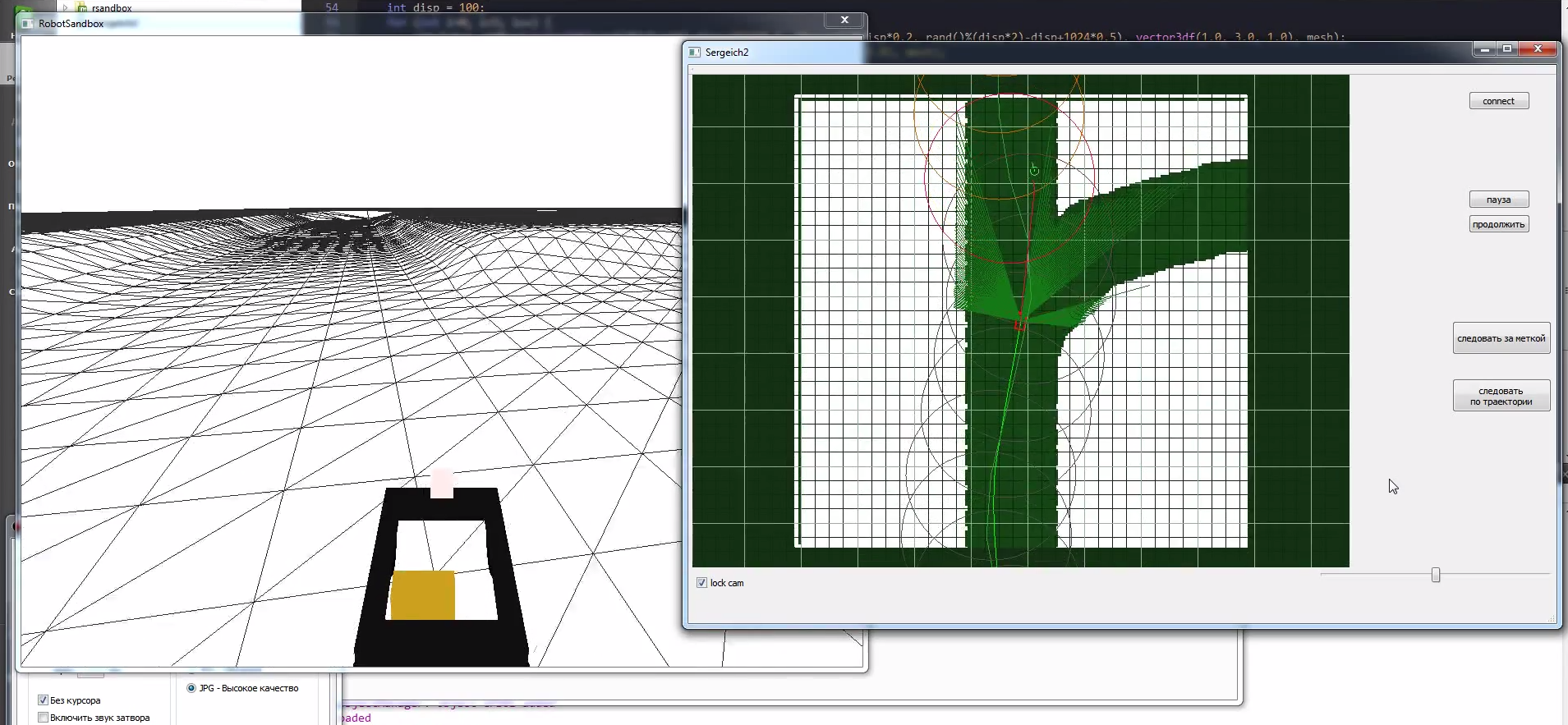
Our simulator The
simulator allowed us to simulate the signals of all sensors (encoders, GPS, SICK), so most of the time debugging took place in the simulator.
But the simulator simulator, and the robot will travel in the real world, which, as a rule, differs from the model. Therefore it is necessary to check everything in practice.
The first (and only) field tests before the competition were held literally - in the field.
The motor overheated
The uppermost part of the algorithm worked well, but the low level was not very good - we had to reconfigure the coefficients of the steering and pedal control knobs (which is logical). By the end of the day we achieved acceptable results. It seems everything turned out.
A small preview of the competition and the final race
Conclusion and conclusions
At RoboCross 2013, our team won first place. We traveled all the barrels and returned safely to the launch area.
A conclusion that suggests itself - a robot car is a complex system. Creating each component is a challenge that developers must accept and overcome, especially in our country. Naturally - the creation of such a device is impossible alone, so I would like to express my gratitude to my team.
I didn’t tell the details when developing electronics, but there they were, it was even more than in software.
The question is what's next? Develop. The system is a fairly holistic view. Improving each of the components should improve the quality of the entire robot. Adding traffic rules logic will only affect the local target selection algorithm. Also, the trend in the global autonomous auto industry is to minimize the cost of the sensors used - expensive laser scanners try not to use, but to focus on cheaper vision systems. It is necessary to move in this direction.
In a classic car, the swivel wheels are the front wheels - it is easier for a person to drive this way. And if you make all the wheels turning? This will make it possible to perform more complex maneuvers, ranging from parallel parking to row-to-row adjustment without sacrificing speed. A person with such control is unlikely to cope, but the robot can:
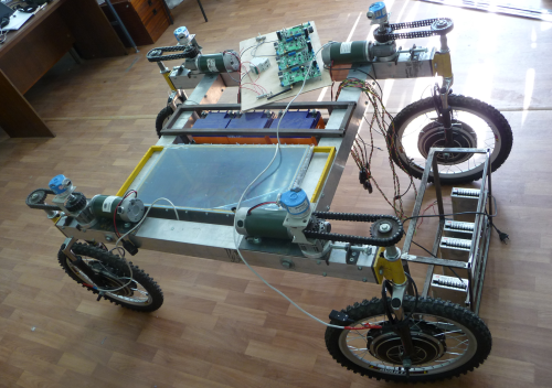
Robot "Maracay". In development
Other laboratory projects and robots can be found here .
ps The purpose of this material is also a search for like-minded people - we are starting the opensource software project for robotic vehicles. If you are interested in this topic, you have experience in development (or are a member of other teams) write me -
 .
.Sources
1. Yoshiaki Kuwata, Gaston A. Firore, et al, “Motion Planning for Urban Driving using RRT,” 2008 IEEE RSJ International Conference on Intelligent Robots and System, September, 2008.
Source: https://habr.com/ru/post/195358/
All Articles