Procedural generation of three-dimensional models
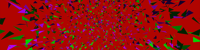
Procedural generation is a great thing! The most interesting thing is to work with graphics, especially three-dimensional - the result is immediately visible. Just a couple of instructions are enough to create a cloud of triangles like in the image above.
Procedural generation of models can help save the size of the distribution, add customization of game characters, at worst, you can simply use it to create special effects.
')
Using the example of the Unity engine and C #, I will show how you can work with models and turn text into graphics. Most of the given code can be easily ported to other frameworks and languages.
Triangle
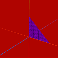
Let's start with the simplest form - a triangle. In Unity and in many other engines, a popular way of describing models is used: using arrays of vertices, triangles and normals. Additionally, the vertex uv coordinates are used for texturing. To work with models there is a class Mesh , in which there is a separate array for each data set. The coordinates of the vertices are stored in Mesh.vertices , in Mesh.triangles - the indexes of the vertices in groups of three. And in Mesh.normals and Mesh.uv are normal vectors and coordinates of uv-maps, the indices of which must coincide with the indices of the corresponding vertices, i.e. the order in the arrays must be the same. I will show an example to make it clearer.
Let's make a function that accepts three vertices of the triangle as input, and gives the finished model one. Let's start with the basics.
public static Mesh Triangle(Vector3 vertex0, Vector3 vertex1, Vector3 vertex2) { var mesh = new Mesh(); mesh.vertices = new [] {vertex0, vertex1, vertex2}; mesh.triangles = new [] {0, 1, 2}; return mesh; } We pack three vertices into an array and pass to the meshu. The triangle is described elementarily, but there is a nuance that needs to be remembered. If you look at the model from the outside, then the vertices of its triangles should be positioned clockwise. This is done so that during drawing it is possible to cut off the triangles that “do not look into the camera,” and process them separately. The order of the vertices is calculated very simply, so this filtering method is very efficient. If we take the product of two vectors, then we can find the third vector perpendicular to the plane formed by the factors. If you run through the triangle and count the pieces, you can find out the order of the vertices. By the way, we also need these perpendicular vectors to describe the models - this is normal. The normal is considered as follows:
var normal = Vector3.Cross((vertex1 - vertex0), (vertex2 - vertex0)).normalized; First two vectors were made of three points, and then they were multiplied. This normal will be the same on all vertices of the triangle.
mesh.normals = new [] {normal, normal, normal}; It remains to add uv-coordinates, for three vertices it is easy.
mesh.uv = new [] {new Vector2(0, 0), new Vector2(0, 1), new Vector2(1, 1)}; Well, that's all, the triangle is ready. Now you can use it.
Triangle
public static Mesh Triangle(Vector3 vertex0, Vector3 vertex1, Vector3 vertex2) { var normal = Vector3.Cross((vertex1 - vertex0), (vertex2 - vertex0)).normalized; var mesh = new Mesh { vertices = new [] {vertex0, vertex1, vertex2}, normals = new [] {normal, normal, normal}, uv = new [] {new Vector2(0, 0), new Vector2(0, 1), new Vector2(1, 1)}, triangles = new [] {0, 1, 2} }; return mesh; } Quadrilateral

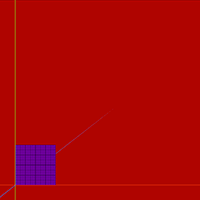
In addition to the triangles, there is another popular primitive for modeling - a quadrilateral, or a quad, if you prefer.
To describe a quadrilateral droplet is more difficult, you need to add one vertex with its characteristics and an additional triangle. I slightly changed the input parameters compared to the triangle, now I need to specify the lower left corner and two sides, with real Quads Mesh in Unity still does not work.
I remind you that the vertices are still recorded clockwise.
Quadrilateral
public static Mesh Quad(Vector3 origin, Vector3 width, Vector3 length) { var normal = Vector3.Cross(length, width).normalized; var mesh = new Mesh { vertices = new[] { origin, origin + length, origin + length + width, origin + width }, normals = new[] { normal, normal, normal, normal }, uv = new[] { new Vector2(0, 0), new Vector2(0, 1), new Vector2(1, 1), new Vector2(1, 0) }, triangles = new[] { 0, 1, 2, 0, 2, 3} }; return mesh; } Now that we have two basic primitives, we can build any model.
Plane
Let's experiment with the assembly of models on the example of a plane. Take a lot of squares and lay the joint into a joint.
Laziness is the engine of progress, so we will use Mesh.CombineMeshes to build the squares into the model. This method takes as input a CombineInstance structure in which you can specify the model, its index, and the transformation matrix. For us, only the first is important, the rest is ignored.
The starting position of the plane, the width and length of the segment, the number of segments are fed to the input of the method. In a double loop, all the squares are added to the CombineInstance array, after which the array is assembled into the finished model.
Plane
public static Mesh Plane(Vector3 origin, Vector3 width, Vector3 length, int widthCount, int lengthCount) { var combine = new CombineInstance[widthCount * lengthCount]; var i = 0; for (var x = 0; x < widthCount; x++) { for (var y = 0; y < lengthCount; y++) { combine[i].mesh = Quad(origin + width * x + length * y, width, length); i++; } } var mesh = new Mesh(); mesh.CombineMeshes(combine, true, false); return mesh; } Parallelepiped

Laying tiles on the plane is too simple, it's time to move to the third dimension.
Cubes are well made from squares. Even better, using our pseudo-squares, you can make not only cubes, but also parallelepipeds. Only shhh! Don't tell anyone.
Only six quadrangles are needed. Knowing the length, width and height of the parallelepiped, one can calculate all its vertices. It is convenient to first find two opposite corners of the parallelepiped, and then rebuild everything else from them. It also makes sense to center the model. How it looks in practice can be viewed below.
Parallelepiped
public static Mesh Cube(Vector3 width, Vector3 length, Vector3 height) { var corner0 = -width/2 - length/2 - height/2; var corner1 = width/2 + length/2 + height/2; var combine = new CombineInstance[6]; combine[0].mesh = Quad(corner0, length, width); combine[1].mesh = Quad(corner0, width, height); combine[2].mesh = Quad(corner0, height, length); combine[3].mesh = Quad(corner1, -width, -length); combine[4].mesh = Quad(corner1, -height, -width); combine[5].mesh = Quad(corner1, -length, -height); var mesh = new Mesh(); mesh.CombineMeshes(combine, true, false); return mesh; } Octahedron
The octahedron is much like a cube, its vertices are very easy to calculate, the biggest difficulty is to figure out the order of the vertices in the triangles. The octahedron fits into the sphere, so it makes sense to build it along the radius of this sphere. All vertices are elementary, so I will not stop here.
Octahedron
public static Mesh Octahedron(float radius) { // var v0 = new Vector3(0, -radius, 0); // var v1 = new Vector3(-radius, 0, 0); var v2 = new Vector3(0, 0, -radius); var v3 = new Vector3(+radius, 0, 0); var v4 = new Vector3(0, 0, +radius); // var v5 = new Vector3(0, radius, 0); var combine = new CombineInstance[8]; combine[0].mesh = Triangle(v0, v1, v2); combine[1].mesh = Triangle(v0, v2, v3); combine[2].mesh = Triangle(v0, v3, v4); combine[3].mesh = Triangle(v0, v4, v1); combine[4].mesh = Triangle(v5, v2, v1); combine[5].mesh = Triangle(v5, v3, v2); combine[6].mesh = Triangle(v5, v4, v3); combine[7].mesh = Triangle(v5, v1, v4); var mesh = new Mesh(); mesh.CombineMeshes(combine, true, false); return mesh; } 
Although there is one more thing. Until now, many of the vertices in our models were duplicated, although, as you may have heard, when creating models, on the contrary, they always try to reduce the number of vertices and triangles. Why is the cube and octahedron wrong? Let me show with an example, here is the octahedron assembly code with the minimum number of vertices necessary:
Octahedron with common vertices at triangles
public static Mesh Octahedron(float radius) { var v = new Vector3[6]; v[0] = new Vector3(0, -radius, 0); v[1] = new Vector3(-radius, 0, 0); v[2] = new Vector3(0, 0, -radius); v[3] = new Vector3(+radius, 0, 0); v[4] = new Vector3(0, 0, +radius); v[5] = new Vector3(0, radius, 0); var mesh = new Mesh { vertices = v, triangles = new[] { 0, 1, 2, 0, 2, 3, 0, 3, 4, 0, 4, 1, 5, 2, 1, 5, 3, 2, 5, 4, 3, 5, 1, 4} }; mesh.RecalculateNormals(); return mesh; } In the end, I applied Mesh.RecalculateNormals , which automatically counts the normals, it's easier.
Look at the difference in lighting between the two octahedra in the next picture. In the first case, the shader has to interpolate between normals, looking completely different directions, so the lighting is unrealistic. And in the second case, all the faces are sharp, clear. General normals are suitable for spheres, smooth surfaces, or if you need to hide a small number of polygons. And for our case, the peaks need more.
Tetrahedron
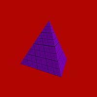
Now you can take on the interesting figures. Calculating vertices even for a simple tetrahedron will require a five for school geometry, so I’m just warning you, if you don’t remember what is divided in the sine, it’s best to look at the textbook first, as I had to do.
Refresh your memory? We continue.
Let our tetrahedron stand on one of the faces, then you can add the opposite vertex right away:
var v = new Vector3[4]; v[0] = new Vector3(0, 1, 0); The remaining vertices must form an equilateral triangle. Their coordinates can be found using sines and cosines. In Unity, there are functions Mathf.Sin and Mathf.Cos , which are calculated in radians. We divide the circle into three parts and find three points on it:
var segmentAngle = Mathf.PI * 2 / 3; var currentAngle = 0f; for (var i = 1; i <= 3; i++) { v[i] = new Vector3(Mathf.Sin(currentAngle), 0, Mathf.Cos(currentAngle)); currentAngle += segmentAngle; } It is already possible to assemble a pyramid from these vertices, but this will not be a tetrahedron, because in a real tetrahedron all the faces are the same. For a real tetrahedron, the base of the pyramid needs to be slightly reduced and shifted below. Here again, the sines and cosines will come in handy, but in order to use them, we swell a little and see one corner on Wikipedia . “Edge central angle” is the angle between the radii of the described sphere intersecting the vertices of the tetrahedron. Hmm, or something like that, I managed to get confused while formulating a thought. In general, adding this angle we get the following code:
var tetrahedralAngle = Mathf.PI * 119.4712f / 180; And in the loop:
v[i] = new Vector3(Mathf.Sin(currentAngle) * Mathf.Sin(tetrahedralAngle), Mathf.Cos(tetrahedralAngle), Mathf.Cos(currentAngle) * Mathf.Sin(tetrahedralAngle)); Not so difficult, I hope everyone understood everything. This is how it looks in the end, with the addition of scaling:
Tetrahedron more difficult
public static Mesh Tetrahedron(float radius) { var tetrahedralAngle = Mathf.PI * 109.4712f / 180; var segmentAngle = Mathf.PI * 2 / 3; var currentAngle = 0f; var v = new Vector3[4]; v[0] = new Vector3(0, radius, 0); for (var i = 1; i <= 3; i++) { v[i] = new Vector3(radius * Mathf.Sin(currentAngle) * Mathf.Sin(tetrahedralAngle), radius * Mathf.Cos(tetrahedralAngle), radius * Mathf.Cos(currentAngle) * Mathf.Sin(tetrahedralAngle)); currentAngle = currentAngle + segmentAngle; } var combine = new CombineInstance[4]; combine[0].mesh = Triangle(v[0], v[1], v[2]); combine[1].mesh = Triangle(v[1], v[3], v[2]); combine[2].mesh = Triangle(v[0], v[2], v[3]); combine[3].mesh = Triangle(v[0], v[3], v[1]); var mesh = new Mesh(); mesh.CombineMeshes(combine, true, false); return mesh; } But the same tetrahedron without mathematics, with hard-coded vertices, feel the difference:
Tetrahedron easier
public static Mesh Tetrahedron(float radius) { var v0 = new Vector3(0, radius, 0); var v1 = new Vector3(0, -radius * 0.333f, radius * 0.943f); var v2 = new Vector3(radius * 0.816f, -radius * 0.333f, -radius * 0.471f); var v3 = new Vector3(-radius * 0.816f, -radius * 0.333f, -radius * 0.471f); var combine = new CombineInstance[4]; combine[0].mesh = Triangle(v0, v1, v2); combine[1].mesh = Triangle(v1, v3, v2); combine[2].mesh = Triangle(v0, v2, v3); combine[3].mesh = Triangle(v0, v3, v1); var mesh = new Mesh(); mesh.CombineMeshes(combine, true, false); return mesh; } Icosahedron
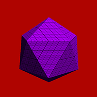
Finally, the most delicious - icosahedron. If you align the icosahedron and look at it from the right angle, you can see that its two vertices lie on one axis below each other, and the rest are on two circles.
On each circle there are five of them, and therefore the interval between them is 72 degrees. The offset between the circles is 36 degrees. To align the vertices, we again need the magic angle from Wikipedia : “If you’re at latitude (1/2) ≈ ± 26.57 ° ". Translated into Russian, this means that the magic angle is one second arctangent .
In the end, everything looks like a tetrahedron, just two circles and a bit more complicated coupling of vertices. Immediately add two vertices, count one half, then the other. We collect in triangles in four portions.
Icosahedron
public static Mesh Icosahedron(float radius) { var magicAngle = Mathf.PI * 26.565f/180; var segmentAngle = Mathf.PI * 72 / 180; var currentAngle = 0f; var v = new Vector3[12]; v[0] = new Vector3(0, radius, 0); v[11] = new Vector3(0, -radius, 0); for (var i=1; i<6; i++) { v[i] = new Vector3(radius * Mathf.Sin(currentAngle) * Mathf.Cos(magicAngle), radius * Mathf.Sin(magicAngle), radius * Mathf.Cos(currentAngle) * Mathf.Cos(magicAngle)); currentAngle += segmentAngle; } currentAngle = Mathf.PI*36/180; for (var i=6; i<11; i++) { v[i] = new Vector3(radius * Mathf.Sin(currentAngle) * Mathf.Cos(-magicAngle), radius * Mathf.Sin(-magicAngle), radius * Mathf.Cos(currentAngle) * Mathf.Cos(-magicAngle)); currentAngle += segmentAngle; } var combine = new CombineInstance[20]; combine[0].mesh = Triangle(v[0], v[1], v[2]); combine[1].mesh = Triangle(v[0], v[2], v[3]); combine[2].mesh = Triangle(v[0], v[3], v[4]); combine[3].mesh = Triangle(v[0], v[4], v[5]); combine[4].mesh = Triangle(v[0], v[5], v[1]); combine[5].mesh = Triangle(v[11], v[7], v[6]); combine[6].mesh = Triangle(v[11], v[8], v[7]); combine[7].mesh = Triangle(v[11], v[9], v[8]); combine[8].mesh = Triangle(v[11], v[10], v[9]); combine[9].mesh = Triangle(v[11], v[6], v[10]); combine[10].mesh = Triangle(v[2], v[1], v[6]); combine[11].mesh = Triangle(v[3], v[2], v[7]); combine[12].mesh = Triangle(v[4], v[3], v[8]); combine[13].mesh = Triangle(v[5], v[4], v[9]); combine[14].mesh = Triangle(v[1], v[5], v[10]); combine[15].mesh = Triangle(v[6], v[7], v[2]); combine[16].mesh = Triangle(v[7], v[8], v[3]); combine[17].mesh = Triangle(v[8], v[9], v[4]); combine[18].mesh = Triangle(v[9], v[10], v[5]); combine[19].mesh = Triangle(v[10], v[6], v[1]); var mesh = new Mesh(); mesh.CombineMeshes(combine, true, false); return mesh; } Conclusion
If you carefully read the code in the article, you probably noticed that there are a lot of unnecessary calculations, the same Mathf.Cos (magicAngle) from the example above. If desired, it can be counted only once and put into a variable, it will not be so clear and understandable, but faster.
In addition, the generated models are not the most convenient uv-cards, it would be nice to fix them, but for this you have to redo a lot of code, and so far it will come down.
And where are the spheres and cylinders? - you ask. The editor of articles on Habrahabr, of course, is wonderful, but navigating through large volumes of text in it is not very convenient, so I will leave the spheres for the next time.
Sources and binaries for different platforms can be downloaded from the links below.
Note: The code for the links below is outdated; see the Procedural Toolkit for the latest version.
Unity Web Player | Windows | Linux | Mac | Sources on GitHub

Source: https://habr.com/ru/post/194620/
All Articles