Printed circuit board production technology
The last time I made a circuit board, when there was no Internet, laser printers and other modern nonsense, but there was adhesive tape, a scalpel and a lot of free time. And now for me the time has come to return to the solution of this problem.
Now, it seems, everything is there, but the problem remains. It’s clear to everyone that the order of printed circuit boards in a specialized production is inconvenient when you need to make only one piece, or a prototype. That's why they use LUT, photoresist, milling, in general, who can. But you want without the development of special skills to get a guaranteed and repeatable result. So let's get started ...
Once I came across this article . An interesting method has been proposed that provides an impeccable result, and completely changes the attitude of home PCB production.
Literally in two words technology
It differs from LUT in the method of transferring toner to board foil. Namely, it is supposed to place the blank of foil material on a flat surface, on top, as usual, a printer print. But above is a flexible heating element, which must be tightly and evenly pressed in the fixture. After that, heat is turned on until the melting point of the toner is reached.
And about the proposed implementation
As a heating element in the article it is proposed to use food foil, and in order to warm it up, a current of about 200 amperes is passed through it at a voltage of about 1 volt. Nice, isn't it?
')
I see some flaws:
- High current implies increased requirements for wires, contacts and tires. This increases the cost of construction. In addition, hard wires create inconvenience, well, in general ...
- Transformer must be fenced
- Foil shaky. However, this is more a question of aesthetics.
- The whole structure is excessively bulky.
However, it is possible that this implementation will please someone.
Obviously, the problem creates a foil, or rather, the low resistance of the heating element based on it. Still, the specific resistivity of aluminum is one of the smallest - look at the table . And we would have something from the end of the list, for example nichrome, at worst, constantan. There is a foil or ribbon of similar materials in nature, but it is unlikely to buy comfortably less than a wagon.
However, over time, two working options were born:
- Ugletkan. As usual, it is sold in meters. When I managed to get a piece of a reasonable size, and I twisted it in my hands, the idea gave a little bit of pleasure. Threads crawl away easily, moreover, they are intertwined in different directions, that is, the current will not go through all. But it should work.
- Mask color picture tube, or TV. It just appeared that the resistivity of the Invar from which it is made should be good, but I still have not found reliable data ... We must try.
Getting a printer print
So, we make a mirror print on a laser printer. I used a backing from self-adhesive labels. It had to be polished, otherwise the toner crumbled. As a result, the villi remained. Most of the villi later stuck to the board (which did not create a problem), but some of them, along with the toner, remained on the substrate, which is already unpleasant. Here it is, the human factor! I later tinted these places with a permanent marker. In general, this moment was not worked out perfectly for me, but it seems that it has been solved globally. It was just that, apparently, it was worth ordering this , but, unfortunately, I met it too late. Or maybe it should get Oracal 651 .
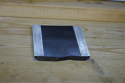
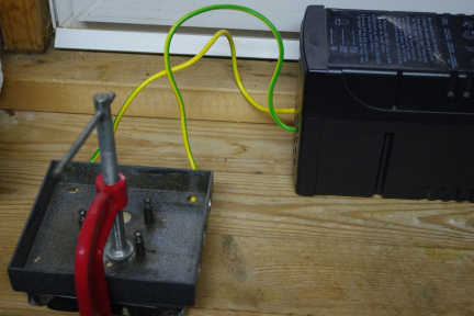
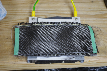
My gadget
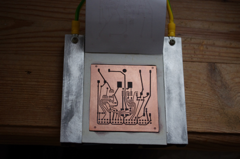
The whole structure is assembled from scrap materials, the photographs can be seen. Tires protrude to the board height, i.e. about 1.5 mm. The board is surrounded by a frame made of cardboard, it is not necessary, but very desirable, because it helps to keep the heating element even.
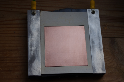
The following photo shows the heating element cut out of the mask is laid on top of the printer print. And it is made of such size that there was contact with aluminum tires.
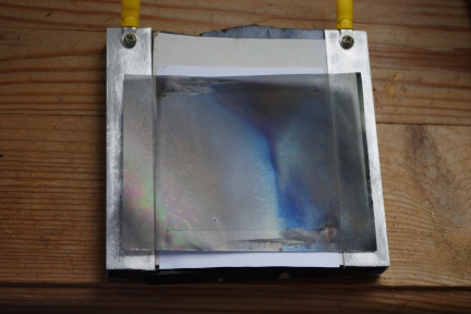
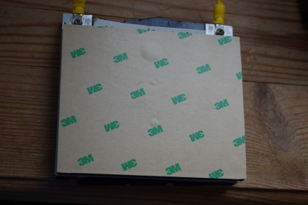
For uniform pressure distribution, I applied a plate of porous silicone 8 mm thick. Laid over the heating element, it presses it tightly simultaneously to the board and aluminum tires, providing good electrical contact with them . This made the fixture very simple and convenient. I was afraid that the plate was too soft and thick, but it turned out - just right. This is what porous silicone looks like:
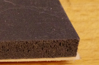
“3M” on the reverse side is a kind of substrate, because I got the self-adhesive plate. Of course, you will not find one in a nearby store, but perhaps several layers of ordinary silicone cut from a baking dish will do. You can take any soft rubber, but it will have to be insulated with the same silicone.
Porous rubber is pressed on top of the metal plate. If the rubber is soft enough, I think you can press it with thick plywood.
In my case, this sandwich is compressed with a clamp. For a small experimental setup, this is enough, and you can figure out something quick-clamping. When tightening the clamp, I did not attach much effort, it turned out 2.5 turns, but it all depends on the hardness of the rubber used.
Now you can measure the resistance of the heating element. Roughly it was 0.05 Ohms with a heating zone of 80 x 80 mm. By the way, the resistance of the carbon fabric element is about 0.35 ohms.
Heating lasted one minute, the power consumption was about 350 watts. Perhaps these are not optimal modes, and you should keep a few minutes at a lower power, but for now I have decided to stop at this. Here is the finished result:
What should be added
Since the mask is spherical, it may not be pressed fully against the surface of the board of large sizes. But on the latest models of extinct kinescopes nowadays, it is fairly flat. By the way, I got it from a 15 "monitor. Using a carbon cloth or carbon fiber is also tempting, especially if you manage to fix it on a suitable basis. This is what the carbon cloth looks like in my experiment:
And what's in the black box?
For heating requires a relatively large current and the possibility of its adjustment. Here you can apply different solutions, and perhaps you already have something ready. I could not find anything suitable, so I had to invent it myself. As a result, the following construction was built from improvised means:

From the UPS, only the case and the transformer are left, the primary winding of the transformer is supplied with voltage from the power regulator from the vacuum cleaner. As a regulator, you can use a simple dimmer of sufficient power, or you can solder a homemade one. The heating element is connected directly to half of the secondary winding of the transformer.
The heating power (we are interested in the specific power, i.e. the power per unit heating area) can vary over a wide range. So, in the original article it turns out that it was 0.9 W / cm 2 , and my experience was carried out at 5.5 W / cm 2 .
And what about the etching?
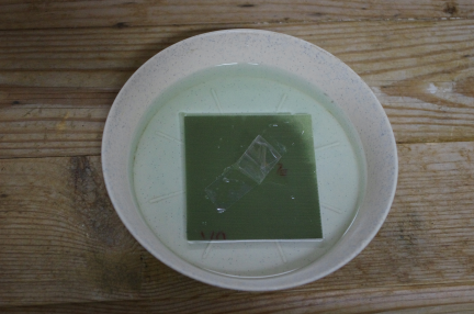
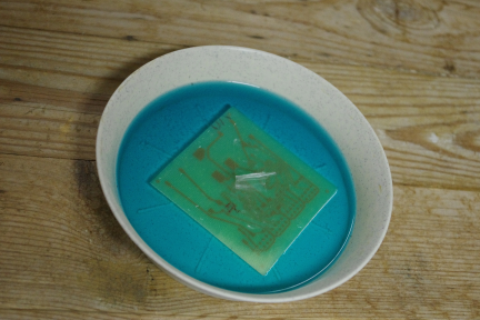
For etching applied the method based on hydrogen peroxide . This has already been written on Habré . But the method deserves additional mention, at least for the completion of statistics.
So, the size of my board is 65 x 68 mm. The etching took place under the following conditions.
I dissolved 16 g of citric acid (2 sachets of 8 g each) and a spoon (by eye) of salt in 50 ml of 3% hydrogen peroxide.
The scarf melted for 45 minutes, periodically I took it out to look, and at the same time I mixed the solution slightly.
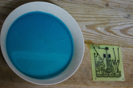
Final result:
UPD: Corrected the description a bit to make it clearer.
Source: https://habr.com/ru/post/194494/
All Articles