Home automation
Introduction
One fine day I received a mail notification about the debt for hot water, due to the late notification of public utilities about water meter readings. At that moment, I, for idle curiosity, was mastering the WiFi radio module from “Roving Networks” in order to “train” it to remotely turn on / off the electric water heater to save electricity with a long absence of users. And so it all came together that I decided to reduce these tasks and some other ideas of the “smart home” to practical implementation. And of course, it would not be interesting if I used technologies I knew, so I decided to use as many new and interesting things as possible.
Formulation of the problem
The apartment has two cold water meters, two hot water meters and an electric meter. Also has a boiler, with a capacity of 1.5 kW. Due to the actual absence of hot water, the relevant meters are used exclusively to take readings that are always approximately zero. During the first stage of automation, only one of the cold water meters, the electric meter and the boiler will be subjected. In accordance with this, the formulation of the problem was developed:
1. Automate the process of taking readings of a cold water meter and an electric meter. For water meters that are not actually used, provide stubs with constant values.
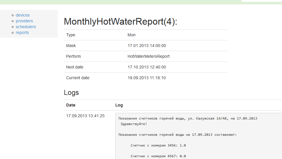
2. Implement email forwarding with meter readings to utilities.
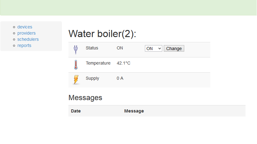
3. Develop a mechanism for remote on (off) the boiler, removal of the magnitude of the instantaneous current consumption and water temperature.
4. Develop a Web service for managing the above mechanisms.
Operating principle
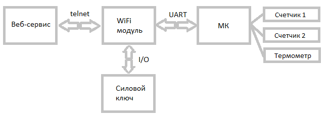
In the figure above, I tried to depict the principle of operation of the designed device. The web service, which acts as a user interface, connects to the WiFi module, which, via the telnet protocol, provides the ability to control its own I / O ports, ADCs and UART interfaces. Own ports of input-output and ADC are used to control the power key of the boiler, while through the UART the microcontroller is accessed to read the counters and the thermometer. To get a better picture of the interaction, I’ll start looking at the individual modules from the bottom up.
Sensors.
')
Sensors
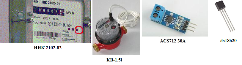
It so happened that by the time the system began to develop, there was an obligation to take my “cold” water meters to the water utility for testing, which became a convenient reason to replace them with the more modern KV-1.5i water meters manufactured by “Electrothermіtya” taking testimony. In this case, the interface was the wire that is connected to the reed switch inside the meter in such a way that the contact closes every 10 liters of water that passes through the meter.
Unfortunately, on the NIK 2102-02 electric meter there were no telemetric outputs, so it was decided to count the number of flashes of the LED indicator, which, according to the documentation, produced 6400 flashes per kilowatt. For this purpose, at the nearest radio market, I acquired a noname phototransistor, among which was one that responded acceptably to the LED indicator.
As a thermometer, I used the DS18b20 thermometer, familiar to lovers of 1wire networks, which was quite easy to make friends with the Attiny2313 microcontroller.
The longest time I chose the current sensor. As a result, I stopped at the ACS712 30A, the principle of which is based on the Hall effect. The sensor required an external power source and at the output gave a voltage value proportional to the current strength relative to the reference voltage equal to Upit / 2.
Power key
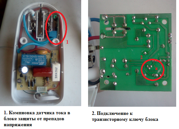
As I said, the power of the water heater is about 1.5 kW, therefore, it is better to control such a load with the help of a relay. And such a relay was found inside a conventional block of protection against voltage drops, bought a long time ago in some kind of supermarket. On the board of this unit, I cut off the track supplying the base of the transistor switch and screwed it to the I / O port of the WiFly module, whose signal was previously amplified using a transistor. The block case turned out to be rather large and additionally contained a current sensor. Thus, the entire power switch with the current sensor was made in the case of the overvoltage protection unit.
Microcontroller
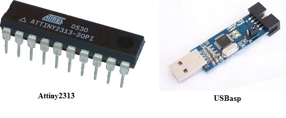
Being an application programmer, I very rarely came across "hardware" and never came across MK, so I chose Attiny2313, examples of which were used on the Internet abound. In addition, the USBasp programmer for AVR microcontrollers was very cheap, only about $ 9. Firmware written in C can be found here: github.com/AndriiArtemenko/UARTSensorsReader . Roughly speaking, the MC is engaged in that it counts external interrupts initiated by the counters and, when the power is turned off, saves the values to non-volatile memory. External commands MK receives via the UART from the WiFly-module and responds to them by sending back data in response. So far I have programmed only 5 commands:
“A” - get the value of the water meter.
“B” - get the value of the electricity meter.
“C” - to get the thermometer value.
“D” - reset the water meter value.
“E” - reset the electricity meter value.
The thermometer ds18b20 is polled by the MK via a normal port using external libraries 1wire and ds18x20_v2. To maintain the performance of the MK in the absence of electricity in the power circuit there is an ionistor for one Farad.
The main difficulties in working with MC caused the bounce of the water meter contacts, which was suppressed programmatically using a timer.
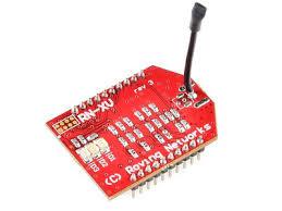
WiFi module
I used RN-171 from Roving Networks, also known as WiFly, as a wifi module. In fact, this is not just a wifi module, but a self-contained device with its own I / O ports, ADC, UART, WEB and FTP clients. A very interesting thing, which I recommend to all enthusiasts.
WiFly was configured to connect to the home network via a wifi router, whose telnet port was forwarded to the wifly module. Thus, it became possible to control the module from the outside.
One of the I / O ports was configured to control the power switch, and one of the ADCs digitizes the current sensor readings. The UART port is directly connected to the MK.
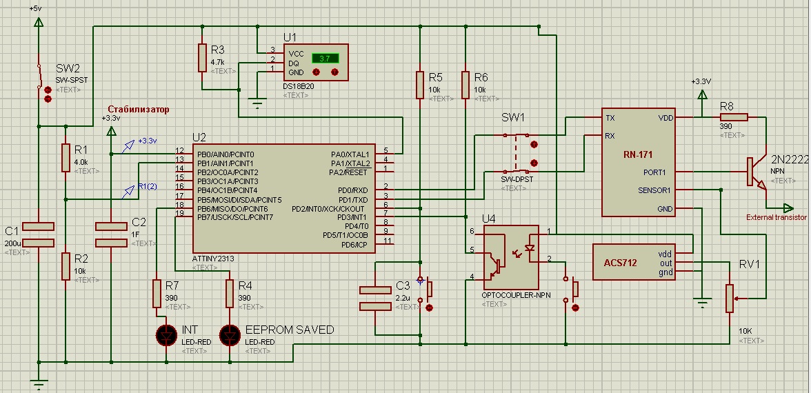
Schematic diagram
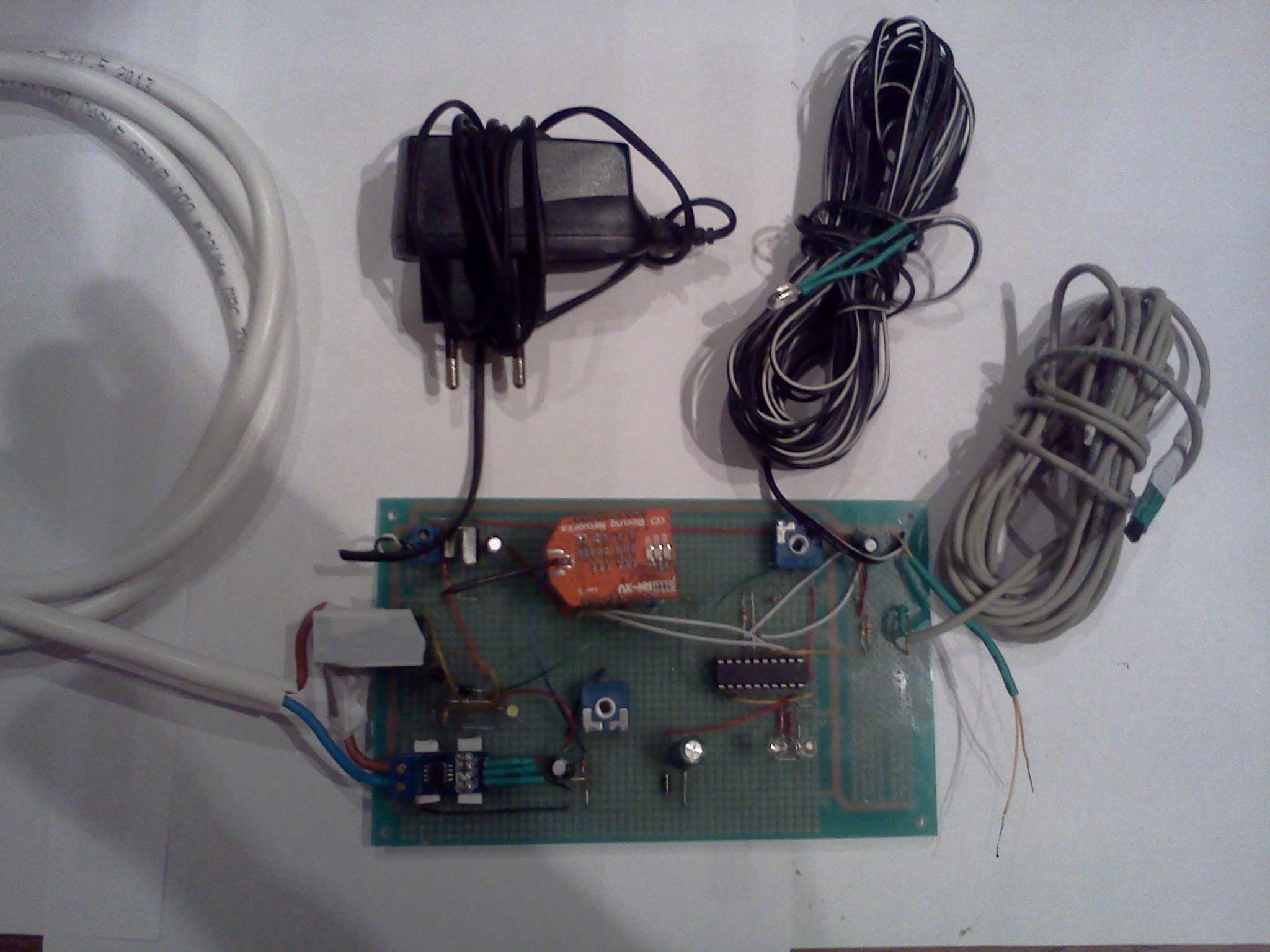
How to live well in the 21st century, when there is no need to keep at home a huge test bench and a set of components for all occasions. I modeled the schematic diagram in Proteus 7 Professional, but only the part that concerned the work of the microcontroller. The part concerning the WiFly module I just finished drawing, for the reason that there was no RN-171 model for Proteus on the Internet. For the same reasons, instead of a phototransistor, an optocoupler is shown in the circuit, instead of counters, buttons, and instead of a voltage stabilizer, just another power output. The rest of the scheme is quite accurate and corresponds to the “iron” prototype. The power supply for the device served as a charging unit from a 5V mobile phone. Only the current sensor and the transistor amplifying signal of the output port are supplied directly from it, the WiFly and MK are 3.3V devices and a stabilizer has been installed for them. At present, the system is at the testing stage, and according to this it is mounted on a circuit board.
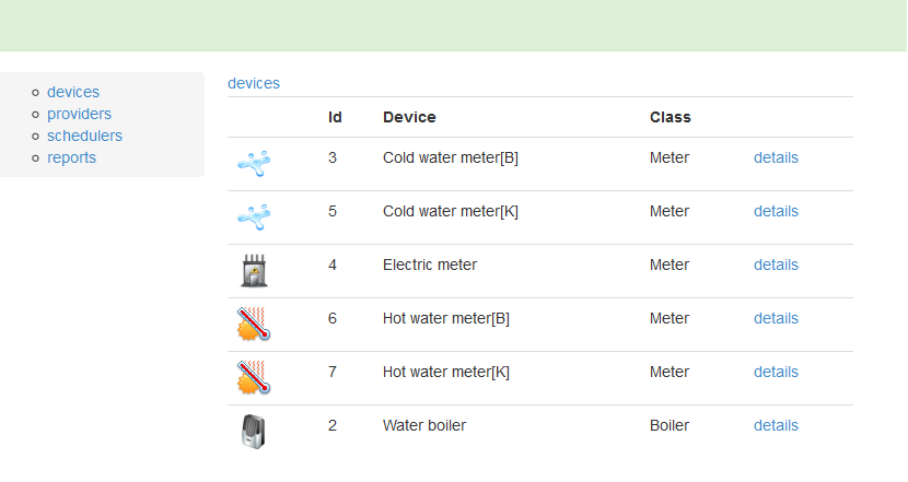
Web service
I decided to create a Web service using Ruby on Rails 3, only for the reason that I really wanted to try to work with this vaunted beast. Initially, I wanted to host the project on Cloud Foundry, but, without waiting for an account, I slipped to Heroku. The source code of the Web application can be viewed here: github.com/AndriiArtemenko/SmartFlat .
The application used the devise, delayed_job_active_record, liquid, simple-navigation, log4r, etc. gems.
At the moment, in addition to displaying the collected data, the application can schedule send emails with meter readings to the appropriate authorities and manage the boiler’s power supply. Of course, this is not enough, but the initial task has been completed, and there are already plans to expand the functionality.
Instead of conclusion
I worked on this task in my spare time and for this reason spent about 3 months on it. During this time, I realized the direction of further development of the project and its relevance. In the near future, I plan to add the ability to automatically pay utility bills through some payment service, add devices for emergency water shut off in the bathroom, and much more.
Thanks
During the entire time of the project, considerable help in designing the hardware was provided to me by the users of the Radiocot forum. Guys, thank you so much!
Source: https://habr.com/ru/post/194402/
All Articles