Intelligent motor cooling fan control relay
After reading mrsom 's post about transplanting a microcontroller filling into a retro-tachometer from Zhiguli , I decided to tell about one of my long-time microcontroller development (2006), made for smooth control of the electric fan cooling fan of VAZ front-wheel drive models.
It must be said that at that time there were already a lot of various solutions - from purely analog to microcontroller ones that perform the necessary function with varying degrees of perfection. One of them was the fan controller of the Silych company (what now looks like this , famous among those interested in its automatic ignition timing regulator programmatically detecting detonation knocks of the engine. For some time I followed the manufacturer's forum of these devices, trying to determine if the device turned out well, and that - not very, and as a result decided to develop his own.
')
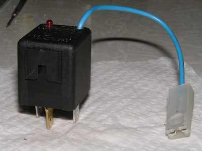
As planned, unlike the solutions existing at that time, the new device had to a) fit into the case of a conventional automotive relay;
b) do not require changes in the standard wiring of the car; c) do not have adjusting elements; d) work reliably and stably in real conditions of operation.
The history of the device and the algorithm of the first version was discussed here - for those who do not want to click, I will describe the key things inline:
-one. The algorithm of operation of the device was assumed to be the following: the voltage was measured on a standard engine temperature sensor; after reaching the lower threshold temperature, the fan started spinning at minimum speed, and in case of further growth linearly increased the rotation speed up to 100% at that moment when, in the opinion of the ECM (motor control controller), it was time to turn the fan on to full capacity.
That is, the temperature value corresponding to 100% of the inclusion could be obtained when the device was first turned on, since It has an input corresponding to the output winding of a regular relay.
The lower threshold in the first version had to be somehow set, having thus conducted a linear regulation characteristic through two points.
0. At currents of the order of 20A, it is obvious that PWM is used for smooth regulation, and a powerful field force is a key element.
1. Placing the device in the case of a conventional relay means the practical absence of a heat sink radiator. And this in turn imposes strict requirements on the power dissipated by the key element in static (channel resistance) and dynamic (switching speed) modes - based on the thermal resistance of the crystal-body, it should not exceed 1 W under any circumstances.
2. The solution for claim 1 may be either the use of a field driver or operation at a low PWM frequency.
In contrast to analogs, for reasons of compactness and noise immunity, the option with a low PWM frequency of only 200 Hz was chosen.
3. Operation of the device with standard wiring and temperature sensor inevitably leads to PIC, since The TKS of the standard temperature sensor is negative, and when the fan is turned on due to the resistance of the common wire and the network’s 'subsidence' of course, the voltage measured on the sensor inevitably drops. However, it is impossible to stabilize or use the four-wire connection scheme - changes in the standard wiring are prohibited.
It was decided to fight this programmatically - by measuring the voltage on the sensor only at the moment when the PWM key is turned off - that is, there is no parasitic voltage drop. Fortunately, the low PWM frequency left enough time for this.
4. Programming the device enable threshold should be either very simple or fully automatic. Initially, a reed switch was installed in the device, by bringing the magnet to which a lower threshold was programmed through the case (the value was naturally remembered in the EEPROM). The upper threshold was set itself at the time of the first pulse from the ECM.
Later on, I came up with and implemented a fully automatic threshold setting algorithm based on finding a thermostable engine point (thermostat triggering point) in the absence of saturation in heat transfer radiator-air.
5. The device must provide diagnostics to the user. For this, an LED was added that flashed two bytes in binary code - the current ADC code and the word of the status flags.
The device was partially assembled by mounting directly on the conclusions of the former relay, partly on a printed scarf tucked from somewhere.
The power MOSFET output drain was soldered directly to the lamella output relay, which increased the margin of power dissipation. The device without glitches worked on the VAZ-2112 from 2006 to 2010, when I took it off before selling, and not only visited the cold St. Petersburg climate, but also on the Crimean mountain roads (and even by car in the supercharged version - I was at the inlet drive compressor), despite the installation of the prototype level and the controller in the socket.
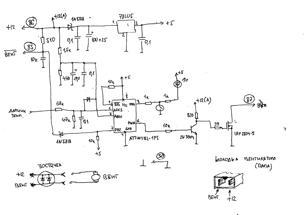
Here is the original scheme (painted only on paper):
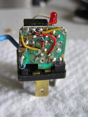
And this is a view of the device from the inside:

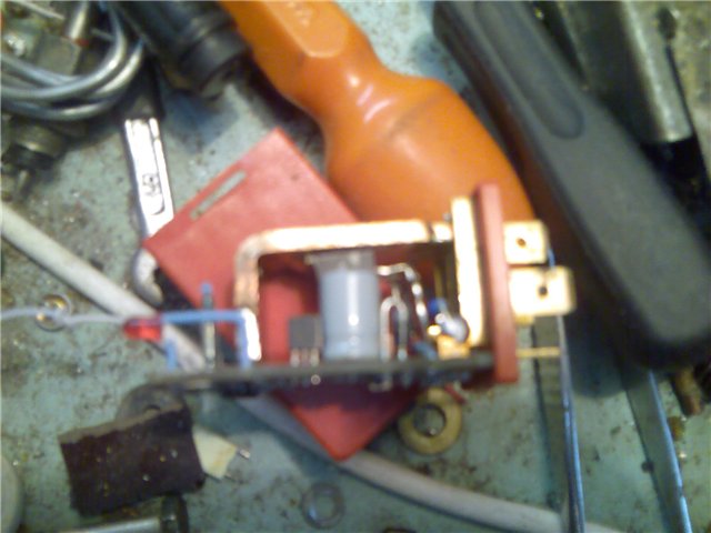
The device was repeated by several people, one of them (off-roder Gennady Olomutsky from Kiev) used it on UAZ, drawing a diagram in sPlan and spreading out the printed circuit board - in its version it looks like this:
- the scheme, signet and latest version of the code are here: http://code.google.com/p/mc-based-radiator-cooling-fan-control-relay
But a piece from the correspondence with one of those repeating this device - the algorithm (!) Was written out for the first time in detail - before that he wrote directly from the brain to the assembler:
Now the idea and implementation of the auto installation algorithm itself (all the steps below correspond to unset thresholds):
1. We are waiting for the fan switch-on signal from the ECM (or from the temperature sensor in the radiator in the Gennady variant)
2. Remember the temperature at the time of the signal as T1 (actually, the code of the ADC channel for digitizing the sensor signal is actually remembered - let's call it C1)
3. Turn on the fan to 100%. Set the flag “auto-install mode is active (bit 3)”
4. After 3 seconds, read the ADC code (let's call it C1 '). This action is necessary in order to determine the compensation value of the temperature value due to the influence of the current flowing through the fan, and the voltage drop in the measuring circuit caused by it, on the digitized temperature value. In fact, for 3 seconds the motor does not have time to cool down, but the fan starts and goes to the rated current.
5. We calculate the ADC correction for 100% of the fan power (let's call it K100 = C1 - C1 '). Remember K100.
6. We are waiting for the removal of the fan enable signal from the ECM (or disconnecting the sensor in the radiator).
7. Smoothly reduce power from 75% to 12% by about 1.5% per second.
8. Turn off the fan, wait 60 seconds.
9. Remember the temperature as T2 (ADC code C2).
10. Adjust the lower threshold (increase by 1/8 the difference between the upper and lower), so that it is above the thermostable point of the thermostat. T2 = T2 + (T1 - T2) / 8. In the ADC codes, this is C2 = C2 - (C2 - C1) / 8, since the voltage on the sensor decreases with increasing temperature.
11. Store C1, C2, K100 in the internal EEPROM relay.
12. Set the flag “thresholds set” (bit 5), uncheck the flag “auto-install mode active”, exit from auto-install mode to work mode
The idea of the algorithm is that it blows the radiator to a thermostable thermostat point, but does not blow much so as not to cool the engine by direct cooling of the block and the head. Then the fan turns off and the relay gives the motor a little warm up - so we automatically get a point to start the fan.
During auto-installation, the relay perceives the signal from the reed switch during steps 7 and 8 - bringing the magnet to the relay during these moments causes a sequence of steps 9, 11, 12. The threshold is not corrected at step 10, but this is not done).
If during the automatic installation some of the expected relay conditions were violated, the flag “auto-configuration error (bit 4)” is set and the relay exits the automatic installation mode. In order for the relay to again enter this mode by the condition of step 1, it is necessary to turn off and turn on the power of the relay.
Errors are caught such:
Step 2 - ADC value out of range (too low or high). Autoconfiguration range by ADC code 248..24 (11111000 ... 00011000). In this case, the relay simply does not enter autoconfiguration mode without setting the error flag.
Step 4 - during the waiting time of 3 seconds, the removal of an external fan enable signal was detected.
Step 7 - an active external fan start signal was detected during a decrease in revolutions Step 8 - an active external fan switch signal was detected during a wait Step 11 - set thresholds out of the 248..24 range, or C2 – C1 <4 difference (i.e., they are too close each other, or for some reason C2> C1 - for example, when the fan does not actually work, and the temperature continues to rise)
Now working mode:
Calculation of the required power (Preq)
1. If the external signal is active - Preq = 100% 2. If it is inactive, then the current ADC code © and its corresponding temperature T look:
T <T2 (C> C2): Preq = 0%
T> T1 (C <C1): Preq = 100%
T2 <= T <= T1 (C2> = C> = C1): Preq = Pstart + (100% - Pstart) * (C2 - C) / (C2 - C1), where Pstart = initial power (12%)
At the same time, the required power is not immediately supplied to the fan, but passes through an algorithm for smooth acceleration and the limiting of the start / stop frequency of the fan.
This algorithm works only in the operating mode and in the absence of an external enable signal:
Let Pcurr - current fan power
1. If Pcurr> 0 and Preq = 0, or Pcurr = 0 and Preq> 0 - that is, it is necessary to start the stopped or stop the working fan, then:
- Watch the time of finding the fan in this state (started or stopped). If the time is less than the threshold - the state of the fan does not change.
- At the same time, if Pcurr> Pstart and Preq = 0, then for the remainder of the running state, Pcurr = Pstart is set (that is, the fan turns at minimum speed) 2. If item 1 is not executed, or the time in the state has passed, then:
- If Preq <Pcurr, then set Pcurr = Preq (then the change in the rotational speed to the downside occurs immediately, as calculated by the new value)
- If Preq> Pcurr, then the rotation speed is limited to above 1.5% per second (except when the fan is requested by an external signal) - that is, if Preq - Pcurr> Pdelta, then Pcurr = Pcurr + Pdelta, otherwise Pcurr = Preq
Now about the algorithm for digitizing the value of the ADC sensor and compensating spurious feedback when the fan is running:
When calculating the power, the averaged code value of the current temperature C is used (see Calculation of the required power) obtained by the arithmetic average of the last 8 values of Cm1, Cm2, Cm3 ... Cm8. Averaging occurs by the “sliding window” method — that is, placing a new value into a buffer of 8 values pushes the oldest one and causes the arithmetic mean S. to be recalculated. The ADC cycle (and the average recalculation) occurs every 640 ms.
The "raw" (read from the ADC) value Cadc, before it enters the counting buffer, participates in the following algorithm:
1. Verify that Cadc> Cdisc, where Cdics is max. ADC value for non-connected measurement output.
2. If Cadc> Cdisc, then the “sensor is not connected (bit 6)” flag is set, the value does not fall into the buffer of the last 8 values, and the average is not recalculated.
3. If Cadc> = Cdisc - that is, the sensor is connected, then adc is corrected by a certain amount depending on the current fan power and correction value for 100% of the power (see step 4 of the automatic installation algorithm): Cadc = Cadc + curr, where curr = K100 * (Pcurr / 100%). If, in this case, Kcurr> 0, then the “ADC value corrected (bit 7)” flag is set. The correction algorithm works only in the working mode and does not work in the autoconfiguration mode.
4. The negative dynamics of Cadc is limited to suppress abrupt C decreases due to the impulse load shared with the vehicle's power supply temperature sensor: If C - Cadc> Cdelta, then Cadc = C - Cdelta. The restriction does not work during the first 15 seconds after the ignition is turned on, so that the correct values of Cm1, Cm2 ... Cm8 will quickly form in the buffer of values.
5. The Cadc value corrected for power and dynamics is pushed into the value buffer for averaging as Cm1..Cm8 depending on the current value of the buffer head pointer (the buffer is cyclic, the head pointer takes values from 1 to 8).
Now, about the LED diagnostics:
The first byte is the “raw” ADC code (in earlier versions the average value of C was indicated here) The second byte is a status word Between the first and second byte there is a pause of about 1.5 seconds.
Between cycles indication pause 3-4 seconds.
Bytes are displayed bit by bit, starting with the most significant one (bit 7, bit 6, ... bit 0).
A long flash corresponds to a bit set to “1”, a short one to “0”.
State word decoding:
Bit 7 - ADC value corrected for current fan power
Bit 6 - temperature sensor not connected
Bit 5 - thresholds set
Bit 4 - threshold setting error
Bit 3 - autoconfiguration active
Bit 2 - internal processor reset due to a hangup - abnormal situation
Bit 1 - external fan enable signal active
Bit 0 - Purge mode when the engine is stopped.
When I described the algorithm, I was surprised at how I managed to cram it into 1024 words of the tiny15 program memory. However, with a creak, but fit! EMNIP, there were only a couple of dozen free cells. That's what assembly power is :)
UPD: Many people ask for a link to download the code - here is the link to the page where you can click on Download and get the archive: https://code.google.com/archive/p/mc-based-radiator-cooling-fan-control- relay / source / default / source
It must be said that at that time there were already a lot of various solutions - from purely analog to microcontroller ones that perform the necessary function with varying degrees of perfection. One of them was the fan controller of the Silych company (what now looks like this , famous among those interested in its automatic ignition timing regulator programmatically detecting detonation knocks of the engine. For some time I followed the manufacturer's forum of these devices, trying to determine if the device turned out well, and that - not very, and as a result decided to develop his own.
')
As planned, unlike the solutions existing at that time, the new device had to a) fit into the case of a conventional automotive relay;
b) do not require changes in the standard wiring of the car; c) do not have adjusting elements; d) work reliably and stably in real conditions of operation.
The history of the device and the algorithm of the first version was discussed here - for those who do not want to click, I will describe the key things inline:
-one. The algorithm of operation of the device was assumed to be the following: the voltage was measured on a standard engine temperature sensor; after reaching the lower threshold temperature, the fan started spinning at minimum speed, and in case of further growth linearly increased the rotation speed up to 100% at that moment when, in the opinion of the ECM (motor control controller), it was time to turn the fan on to full capacity.
That is, the temperature value corresponding to 100% of the inclusion could be obtained when the device was first turned on, since It has an input corresponding to the output winding of a regular relay.
The lower threshold in the first version had to be somehow set, having thus conducted a linear regulation characteristic through two points.
0. At currents of the order of 20A, it is obvious that PWM is used for smooth regulation, and a powerful field force is a key element.
1. Placing the device in the case of a conventional relay means the practical absence of a heat sink radiator. And this in turn imposes strict requirements on the power dissipated by the key element in static (channel resistance) and dynamic (switching speed) modes - based on the thermal resistance of the crystal-body, it should not exceed 1 W under any circumstances.
2. The solution for claim 1 may be either the use of a field driver or operation at a low PWM frequency.
In contrast to analogs, for reasons of compactness and noise immunity, the option with a low PWM frequency of only 200 Hz was chosen.
3. Operation of the device with standard wiring and temperature sensor inevitably leads to PIC, since The TKS of the standard temperature sensor is negative, and when the fan is turned on due to the resistance of the common wire and the network’s 'subsidence' of course, the voltage measured on the sensor inevitably drops. However, it is impossible to stabilize or use the four-wire connection scheme - changes in the standard wiring are prohibited.
It was decided to fight this programmatically - by measuring the voltage on the sensor only at the moment when the PWM key is turned off - that is, there is no parasitic voltage drop. Fortunately, the low PWM frequency left enough time for this.
4. Programming the device enable threshold should be either very simple or fully automatic. Initially, a reed switch was installed in the device, by bringing the magnet to which a lower threshold was programmed through the case (the value was naturally remembered in the EEPROM). The upper threshold was set itself at the time of the first pulse from the ECM.
Later on, I came up with and implemented a fully automatic threshold setting algorithm based on finding a thermostable engine point (thermostat triggering point) in the absence of saturation in heat transfer radiator-air.
5. The device must provide diagnostics to the user. For this, an LED was added that flashed two bytes in binary code - the current ADC code and the word of the status flags.
The device was partially assembled by mounting directly on the conclusions of the former relay, partly on a printed scarf tucked from somewhere.
The power MOSFET output drain was soldered directly to the lamella output relay, which increased the margin of power dissipation. The device without glitches worked on the VAZ-2112 from 2006 to 2010, when I took it off before selling, and not only visited the cold St. Petersburg climate, but also on the Crimean mountain roads (and even by car in the supercharged version - I was at the inlet drive compressor), despite the installation of the prototype level and the controller in the socket.
Here is the original scheme (painted only on paper):
And this is a view of the device from the inside:
The device was repeated by several people, one of them (off-roder Gennady Olomutsky from Kiev) used it on UAZ, drawing a diagram in sPlan and spreading out the printed circuit board - in its version it looks like this:
- the scheme, signet and latest version of the code are here: http://code.google.com/p/mc-based-radiator-cooling-fan-control-relay
But a piece from the correspondence with one of those repeating this device - the algorithm (!) Was written out for the first time in detail - before that he wrote directly from the brain to the assembler:
Now the idea and implementation of the auto installation algorithm itself (all the steps below correspond to unset thresholds):
1. We are waiting for the fan switch-on signal from the ECM (or from the temperature sensor in the radiator in the Gennady variant)
2. Remember the temperature at the time of the signal as T1 (actually, the code of the ADC channel for digitizing the sensor signal is actually remembered - let's call it C1)
3. Turn on the fan to 100%. Set the flag “auto-install mode is active (bit 3)”
4. After 3 seconds, read the ADC code (let's call it C1 '). This action is necessary in order to determine the compensation value of the temperature value due to the influence of the current flowing through the fan, and the voltage drop in the measuring circuit caused by it, on the digitized temperature value. In fact, for 3 seconds the motor does not have time to cool down, but the fan starts and goes to the rated current.
5. We calculate the ADC correction for 100% of the fan power (let's call it K100 = C1 - C1 '). Remember K100.
6. We are waiting for the removal of the fan enable signal from the ECM (or disconnecting the sensor in the radiator).
7. Smoothly reduce power from 75% to 12% by about 1.5% per second.
8. Turn off the fan, wait 60 seconds.
9. Remember the temperature as T2 (ADC code C2).
10. Adjust the lower threshold (increase by 1/8 the difference between the upper and lower), so that it is above the thermostable point of the thermostat. T2 = T2 + (T1 - T2) / 8. In the ADC codes, this is C2 = C2 - (C2 - C1) / 8, since the voltage on the sensor decreases with increasing temperature.
11. Store C1, C2, K100 in the internal EEPROM relay.
12. Set the flag “thresholds set” (bit 5), uncheck the flag “auto-install mode active”, exit from auto-install mode to work mode
The idea of the algorithm is that it blows the radiator to a thermostable thermostat point, but does not blow much so as not to cool the engine by direct cooling of the block and the head. Then the fan turns off and the relay gives the motor a little warm up - so we automatically get a point to start the fan.
During auto-installation, the relay perceives the signal from the reed switch during steps 7 and 8 - bringing the magnet to the relay during these moments causes a sequence of steps 9, 11, 12. The threshold is not corrected at step 10, but this is not done).
If during the automatic installation some of the expected relay conditions were violated, the flag “auto-configuration error (bit 4)” is set and the relay exits the automatic installation mode. In order for the relay to again enter this mode by the condition of step 1, it is necessary to turn off and turn on the power of the relay.
Errors are caught such:
Step 2 - ADC value out of range (too low or high). Autoconfiguration range by ADC code 248..24 (11111000 ... 00011000). In this case, the relay simply does not enter autoconfiguration mode without setting the error flag.
Step 4 - during the waiting time of 3 seconds, the removal of an external fan enable signal was detected.
Step 7 - an active external fan start signal was detected during a decrease in revolutions Step 8 - an active external fan switch signal was detected during a wait Step 11 - set thresholds out of the 248..24 range, or C2 – C1 <4 difference (i.e., they are too close each other, or for some reason C2> C1 - for example, when the fan does not actually work, and the temperature continues to rise)
Now working mode:
Calculation of the required power (Preq)
1. If the external signal is active - Preq = 100% 2. If it is inactive, then the current ADC code © and its corresponding temperature T look:
T <T2 (C> C2): Preq = 0%
T> T1 (C <C1): Preq = 100%
T2 <= T <= T1 (C2> = C> = C1): Preq = Pstart + (100% - Pstart) * (C2 - C) / (C2 - C1), where Pstart = initial power (12%)
At the same time, the required power is not immediately supplied to the fan, but passes through an algorithm for smooth acceleration and the limiting of the start / stop frequency of the fan.
This algorithm works only in the operating mode and in the absence of an external enable signal:
Let Pcurr - current fan power
1. If Pcurr> 0 and Preq = 0, or Pcurr = 0 and Preq> 0 - that is, it is necessary to start the stopped or stop the working fan, then:
- Watch the time of finding the fan in this state (started or stopped). If the time is less than the threshold - the state of the fan does not change.
- At the same time, if Pcurr> Pstart and Preq = 0, then for the remainder of the running state, Pcurr = Pstart is set (that is, the fan turns at minimum speed) 2. If item 1 is not executed, or the time in the state has passed, then:
- If Preq <Pcurr, then set Pcurr = Preq (then the change in the rotational speed to the downside occurs immediately, as calculated by the new value)
- If Preq> Pcurr, then the rotation speed is limited to above 1.5% per second (except when the fan is requested by an external signal) - that is, if Preq - Pcurr> Pdelta, then Pcurr = Pcurr + Pdelta, otherwise Pcurr = Preq
Now about the algorithm for digitizing the value of the ADC sensor and compensating spurious feedback when the fan is running:
When calculating the power, the averaged code value of the current temperature C is used (see Calculation of the required power) obtained by the arithmetic average of the last 8 values of Cm1, Cm2, Cm3 ... Cm8. Averaging occurs by the “sliding window” method — that is, placing a new value into a buffer of 8 values pushes the oldest one and causes the arithmetic mean S. to be recalculated. The ADC cycle (and the average recalculation) occurs every 640 ms.
The "raw" (read from the ADC) value Cadc, before it enters the counting buffer, participates in the following algorithm:
1. Verify that Cadc> Cdisc, where Cdics is max. ADC value for non-connected measurement output.
2. If Cadc> Cdisc, then the “sensor is not connected (bit 6)” flag is set, the value does not fall into the buffer of the last 8 values, and the average is not recalculated.
3. If Cadc> = Cdisc - that is, the sensor is connected, then adc is corrected by a certain amount depending on the current fan power and correction value for 100% of the power (see step 4 of the automatic installation algorithm): Cadc = Cadc + curr, where curr = K100 * (Pcurr / 100%). If, in this case, Kcurr> 0, then the “ADC value corrected (bit 7)” flag is set. The correction algorithm works only in the working mode and does not work in the autoconfiguration mode.
4. The negative dynamics of Cadc is limited to suppress abrupt C decreases due to the impulse load shared with the vehicle's power supply temperature sensor: If C - Cadc> Cdelta, then Cadc = C - Cdelta. The restriction does not work during the first 15 seconds after the ignition is turned on, so that the correct values of Cm1, Cm2 ... Cm8 will quickly form in the buffer of values.
5. The Cadc value corrected for power and dynamics is pushed into the value buffer for averaging as Cm1..Cm8 depending on the current value of the buffer head pointer (the buffer is cyclic, the head pointer takes values from 1 to 8).
Now, about the LED diagnostics:
The first byte is the “raw” ADC code (in earlier versions the average value of C was indicated here) The second byte is a status word Between the first and second byte there is a pause of about 1.5 seconds.
Between cycles indication pause 3-4 seconds.
Bytes are displayed bit by bit, starting with the most significant one (bit 7, bit 6, ... bit 0).
A long flash corresponds to a bit set to “1”, a short one to “0”.
State word decoding:
Bit 7 - ADC value corrected for current fan power
Bit 6 - temperature sensor not connected
Bit 5 - thresholds set
Bit 4 - threshold setting error
Bit 3 - autoconfiguration active
Bit 2 - internal processor reset due to a hangup - abnormal situation
Bit 1 - external fan enable signal active
Bit 0 - Purge mode when the engine is stopped.
When I described the algorithm, I was surprised at how I managed to cram it into 1024 words of the tiny15 program memory. However, with a creak, but fit! EMNIP, there were only a couple of dozen free cells. That's what assembly power is :)
UPD: Many people ask for a link to download the code - here is the link to the page where you can click on Download and get the archive: https://code.google.com/archive/p/mc-based-radiator-cooling-fan-control- relay / source / default / source
Source: https://habr.com/ru/post/194392/
All Articles