Making your flying robot
About a year ago, there was a message about the competition from Flying Robots by CROC. It was interesting for me to participate and gain experience in designing an autonomous flying robot. Unfortunately, the competition had to be withdrawn due to lack of time, but interest in solving the problem remained. The brief, if briefly, was to fly from point A to point B, flying through a hole in the wall, and return.
What and how it happened at this stage under the cut.
')
The solution to this problem is obviously divided into two parts. The first is how to “fly along the wall without bumping into it,” the second is landing. To orient the robot in space, I decided to use ultrasonic range finders. It turned out that you need at least 3 sensors (down, forward and left, forward and right). It was planned to carry out the landing with the help of a camera, but this has not yet been the case.
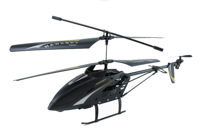
I wanted to build my robot completely autonomous, with all the logic on board. Actually, the issue of aircraft carrying capacity, as well as ease of operation, resistance to falls and low price led me to the choice of a toy radio-controlled helicopter with a co-axle arrangement of screws, the Hawkspy LT-711 model. At one of the sites stated that he can lift the goods up to 50 grams. And as the experiment showed, indeed, not fully charged, he calmly picked up half the standard hundred-gram chocolate.
In order to fly “along the wall” one must first of all be able to keep altitude. Actually, I want to describe the solution to this subtask in this post.
The helicopter body is easily removed and you can immediately see the electronics responsible for flight control. After a close examination of the board, it turned out that it was possible to intervene in the transmission of the control signal by connecting between the radio output and the decoder input.
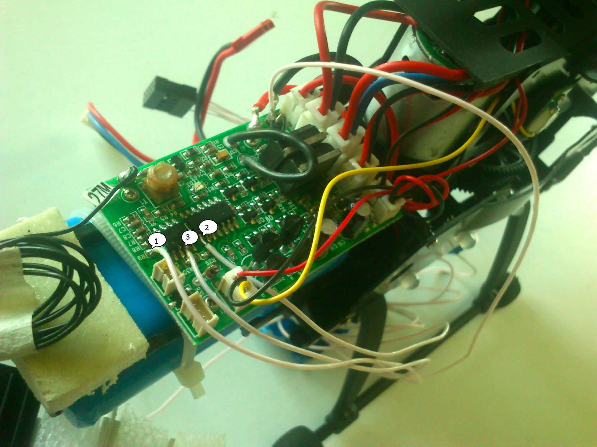
1 - output of the radio receiver (the signal that was decoded); 2 - decoder input (where the signal is fed); 3 - land; On the reverse side of the board, the track connecting pins 1 and 2 was cut.
Thus, you can use the existing control circuit, and not to solder everything from scratch. But for this it was necessary to deal with the control signal, i.e. to solve the problem of reverse engineering signal.

After observing the signal, I was able to isolate characteristic patterns. The picture shows a typical signal with a markup. As a result, it became clear that the signal is encoded quite simply - in four bytes. Playing with the control panel and observing the changes in the signal, we managed to restore which part of the signal is responsible for what. It turned out the following:

lt - enable / disable light bulbs on the helicopter body; sm - turbo mode;
The most difficult was to guess the checksum. It turned out that the checksum is considered in two stages - first the signal is added by-byte, and then the result is summed up by the upper and lower half of a byte.
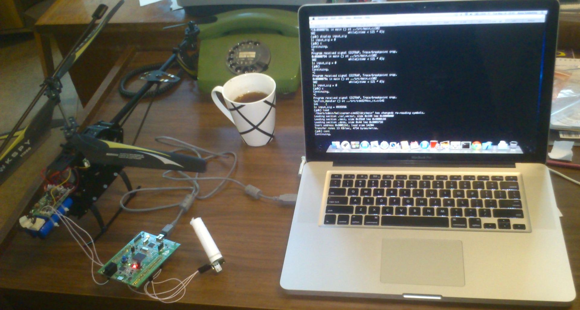
At this stage, most of the preparatory actions were completed and it was time to start writing my own firmware for the microcontroller. I had a stm32f4discovery microcontroller for a long time and I decided to try using it first. A significant part of the time was taken to install and configure the environment. I have MacOS, so I had to install Armchan's phone with linaro and openocd on my laptop. The basis was taken and modified one of the examples from the library for working with peripheral devices. The routines for decoding and encoding the signal were transferred to it. The signal received by the receiver is decoded by the microcontroller program. Controls up / down, turning left / right, moving forward / backward (and others) are represented as separate numbers. At this stage it is easy to modify them. Next, the encoding is performed in the original format and transferred to the regular decoder helicopter.
To solve the problem of measuring height, an ultrasonic distance measuring sensor LV-MAXONAR-EZ0 was used . The sensor was connected to the microcontroller via the UART interface and gave the distance to the object in the cone of its visibility in inches.
Thus, the firmware did the following: took readings from the height sensor, and controlled the rotation speed of the screws using the PID controller .
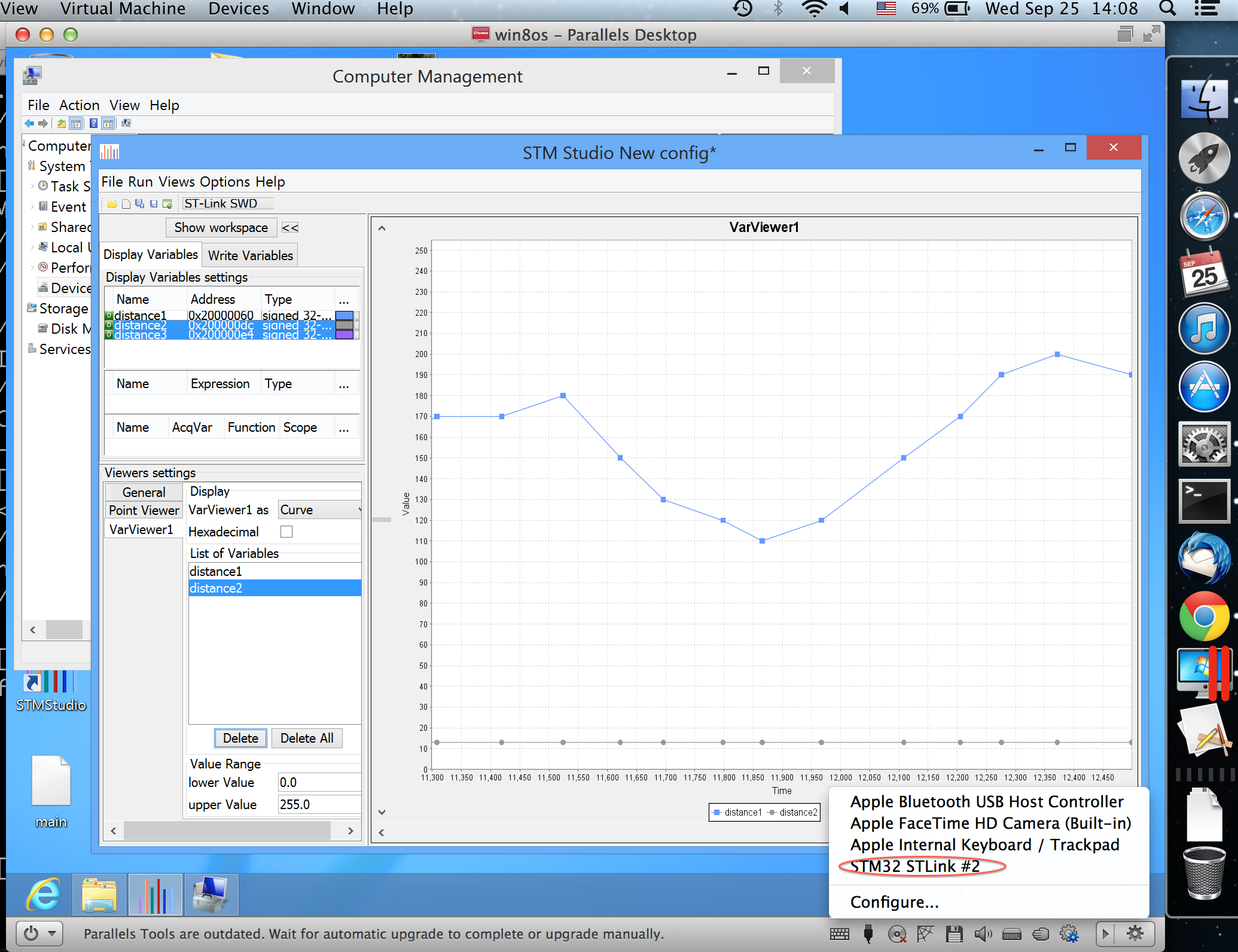
To debug the sensor, there is a very handy tool for STM microcontrollers, STM Studio , which allows you to monitor the values of variables without interrupting the work of the program. True, it works only under Windows, but there was no problem with propping the USB device (debug board) and installing drivers in the virtual machine with Windows (I used PD ). The signal passes through the virtual shell completely, without changes and visible delays, thus online monitoring of the sensor's behavior greatly facilitated the understanding of what is happening.
When it came to test flights, it turned out that all the added electronics weighs more than 50 grams, so the helicopter took off low and almost immediately, slowly and sadly strove to the ground. I had to think how to reduce the weight of all this electronics. It is not possible for me to unsolder the chip on the board myself, so the problem was solved by replacing the debug board with a smaller and lighter MINI-m4 with the same chip. I didn’t have to re-program the firmware: replace a couple of parameters and change the names of some of the pins used.

The debugging of the whole structure consisted in the selection of parameters for the PID controller, but by writing the simplest mathematical model of the helicopter, solved by the standard Euler method of the diffures, it was clear how the helicopter would behave. It was clear that he would fluctuate and eventually go to a stationary state. Therefore, the selection of parameters for the quickest exit from the oscillatory state did not take much time. During the test flights, the helicopter sometimes had to be planted abruptly, so it took several parts to change. Fortunately, for this model of a helicopter to find parts was not a problem. The final step was to add filtering to the data taken from the height sensor. From time to time, during the flight, the helicopter fell down a bit and then flew up sharply as well. So, one of the first steps of further development will be the implementation of the telemetry removal function. As it turned out, the sensor sometimes failed and showed obviously incorrect values, but the addition of filtering solved this problem.
For convenience, the helicopter now has two modes. If the joystick is in the upper half of the range, then the helicopter holds a height of one meter, if the joystick is in the lower half, then this is the landing mode.
Github code
Video
Mat model, with which you can imagine the behavior of a helicopter under the influence of the PID controller. Since I did not come across this before, then, looking at different schedules, you can predict the behavior of a helicopter on test flights. It is also easier to twist the coefficients of the PID controller, and this greatly saves time, because I had to recompile and rebuild every time.
The model is quite primitive, one-dimensional. If someone has ideas for improvement, I will be glad to hear.
What and how it happened at this stage under the cut.
')
The solution to this problem is obviously divided into two parts. The first is how to “fly along the wall without bumping into it,” the second is landing. To orient the robot in space, I decided to use ultrasonic range finders. It turned out that you need at least 3 sensors (down, forward and left, forward and right). It was planned to carry out the landing with the help of a camera, but this has not yet been the case.
I wanted to build my robot completely autonomous, with all the logic on board. Actually, the issue of aircraft carrying capacity, as well as ease of operation, resistance to falls and low price led me to the choice of a toy radio-controlled helicopter with a co-axle arrangement of screws, the Hawkspy LT-711 model. At one of the sites stated that he can lift the goods up to 50 grams. And as the experiment showed, indeed, not fully charged, he calmly picked up half the standard hundred-gram chocolate.
In order to fly “along the wall” one must first of all be able to keep altitude. Actually, I want to describe the solution to this subtask in this post.
The helicopter body is easily removed and you can immediately see the electronics responsible for flight control. After a close examination of the board, it turned out that it was possible to intervene in the transmission of the control signal by connecting between the radio output and the decoder input.
1 - output of the radio receiver (the signal that was decoded); 2 - decoder input (where the signal is fed); 3 - land; On the reverse side of the board, the track connecting pins 1 and 2 was cut.
Thus, you can use the existing control circuit, and not to solder everything from scratch. But for this it was necessary to deal with the control signal, i.e. to solve the problem of reverse engineering signal.
After observing the signal, I was able to isolate characteristic patterns. The picture shows a typical signal with a markup. As a result, it became clear that the signal is encoded quite simply - in four bytes. Playing with the control panel and observing the changes in the signal, we managed to restore which part of the signal is responsible for what. It turned out the following:
lt - enable / disable light bulbs on the helicopter body; sm - turbo mode;
The most difficult was to guess the checksum. It turned out that the checksum is considered in two stages - first the signal is added by-byte, and then the result is summed up by the upper and lower half of a byte.
At this stage, most of the preparatory actions were completed and it was time to start writing my own firmware for the microcontroller. I had a stm32f4discovery microcontroller for a long time and I decided to try using it first. A significant part of the time was taken to install and configure the environment. I have MacOS, so I had to install Armchan's phone with linaro and openocd on my laptop. The basis was taken and modified one of the examples from the library for working with peripheral devices. The routines for decoding and encoding the signal were transferred to it. The signal received by the receiver is decoded by the microcontroller program. Controls up / down, turning left / right, moving forward / backward (and others) are represented as separate numbers. At this stage it is easy to modify them. Next, the encoding is performed in the original format and transferred to the regular decoder helicopter.
To solve the problem of measuring height, an ultrasonic distance measuring sensor LV-MAXONAR-EZ0 was used . The sensor was connected to the microcontroller via the UART interface and gave the distance to the object in the cone of its visibility in inches.
Thus, the firmware did the following: took readings from the height sensor, and controlled the rotation speed of the screws using the PID controller .
To debug the sensor, there is a very handy tool for STM microcontrollers, STM Studio , which allows you to monitor the values of variables without interrupting the work of the program. True, it works only under Windows, but there was no problem with propping the USB device (debug board) and installing drivers in the virtual machine with Windows (I used PD ). The signal passes through the virtual shell completely, without changes and visible delays, thus online monitoring of the sensor's behavior greatly facilitated the understanding of what is happening.
When it came to test flights, it turned out that all the added electronics weighs more than 50 grams, so the helicopter took off low and almost immediately, slowly and sadly strove to the ground. I had to think how to reduce the weight of all this electronics. It is not possible for me to unsolder the chip on the board myself, so the problem was solved by replacing the debug board with a smaller and lighter MINI-m4 with the same chip. I didn’t have to re-program the firmware: replace a couple of parameters and change the names of some of the pins used.
The debugging of the whole structure consisted in the selection of parameters for the PID controller, but by writing the simplest mathematical model of the helicopter, solved by the standard Euler method of the diffures, it was clear how the helicopter would behave. It was clear that he would fluctuate and eventually go to a stationary state. Therefore, the selection of parameters for the quickest exit from the oscillatory state did not take much time. During the test flights, the helicopter sometimes had to be planted abruptly, so it took several parts to change. Fortunately, for this model of a helicopter to find parts was not a problem. The final step was to add filtering to the data taken from the height sensor. From time to time, during the flight, the helicopter fell down a bit and then flew up sharply as well. So, one of the first steps of further development will be the implementation of the telemetry removal function. As it turned out, the sensor sometimes failed and showed obviously incorrect values, but the addition of filtering solved this problem.
For convenience, the helicopter now has two modes. If the joystick is in the upper half of the range, then the helicopter holds a height of one meter, if the joystick is in the lower half, then this is the landing mode.
Github code
Video
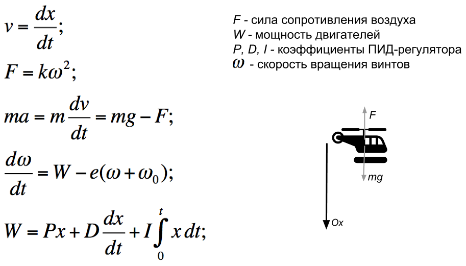
The simplest mathematical model
Mat model, with which you can imagine the behavior of a helicopter under the influence of the PID controller. Since I did not come across this before, then, looking at different schedules, you can predict the behavior of a helicopter on test flights. It is also easier to twist the coefficients of the PID controller, and this greatly saves time, because I had to recompile and rebuild every time.
The model is quite primitive, one-dimensional. If someone has ideas for improvement, I will be glad to hear.
Source: https://habr.com/ru/post/193900/
All Articles