A car dial tachometer for a beginner or some fixed-point shamanism on the AVR
Hello! I would like to share with the community my own history of the modernization of the TX-193 tachometer
A week ago, I was approached by one person with a rather non-standard task - it was necessary to ensure the operation of the ancient tachometer TX-193 (VAZ 2106) with amodern VAZ21126 (Priora) engine, which has an ignition system with individual coils for each cylinder, and therefore simply connect the TX-193 to the ignition coil will not work. In addition, the customer wanted to improve the performance of the device, leaving untouched by its appearance and design. In general, the matter ended with the fact that I undertook to gut the electronic filling of the device and develop my own, with blackjack and whores . Information about the frequency of rotation of the crankshaft tachometer will now receive from the computer January 7.2, for which the latter has a special conclusion.
Under the cut photo, video, scheme, source, and a lot of text, telling about logarithms and how to properly scale the data and get rid of the comma.
')
Hard
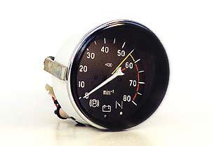
Let's start with the device TX-193 . The mechanical part of the device is a milliammeter of a classical construction, with a permanent magnet and a moving coil, setting the arrow in motion.
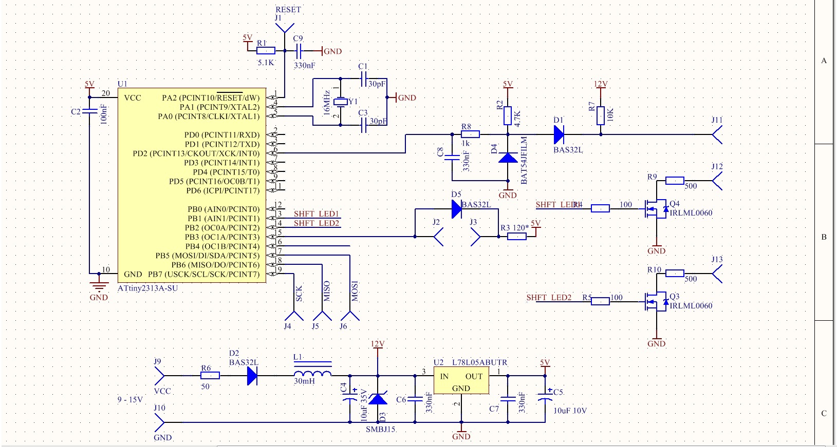
For the development of the circuit, in essence, it was enough to know about the milliammeter only that, at a current of the order of 10 mA, the arrow deviates to the limit, and the winding resistance is approximately 180 Ohm. The ATtiny2313A controller from the renowned Atmel company, clocked from an external quartz crystal at 16 MHz, was chosen as the brain. The device is powered from the vehicle’s on-board network, which means according to GOST it must withstand a “beard” up to 100V and work stably in the range from 9-15V. Due to low consumption (several tens of milliamperes), it was decided to use a 7805 linear stabilizer with an inductive filter and a suppressor to protect against impulse noise. The device was going from what was at hand, so the powerful version 7805 is used in the finished product, although 78L05 per 100mA would be enough.
Milliammeter controller controls, of course, using PWM. For which the 16-bit timer was used in the Phase and Frequency Correct PWM mode.
Information about the frequency of rotation of the crankshaft is transmitted from the computer in the form of pulses from 0 - 12V. The active level is low. 2 pulses per crankshaft revolution. To capture these pulses, an external interrupt INT0 and the corresponding string from the RC filter, suspenders and protective diodes are used. In general, the circuitry of the device is quite typical and I was surprised to find that I had just written so much about it. But do not judge strictly, the first article after all.
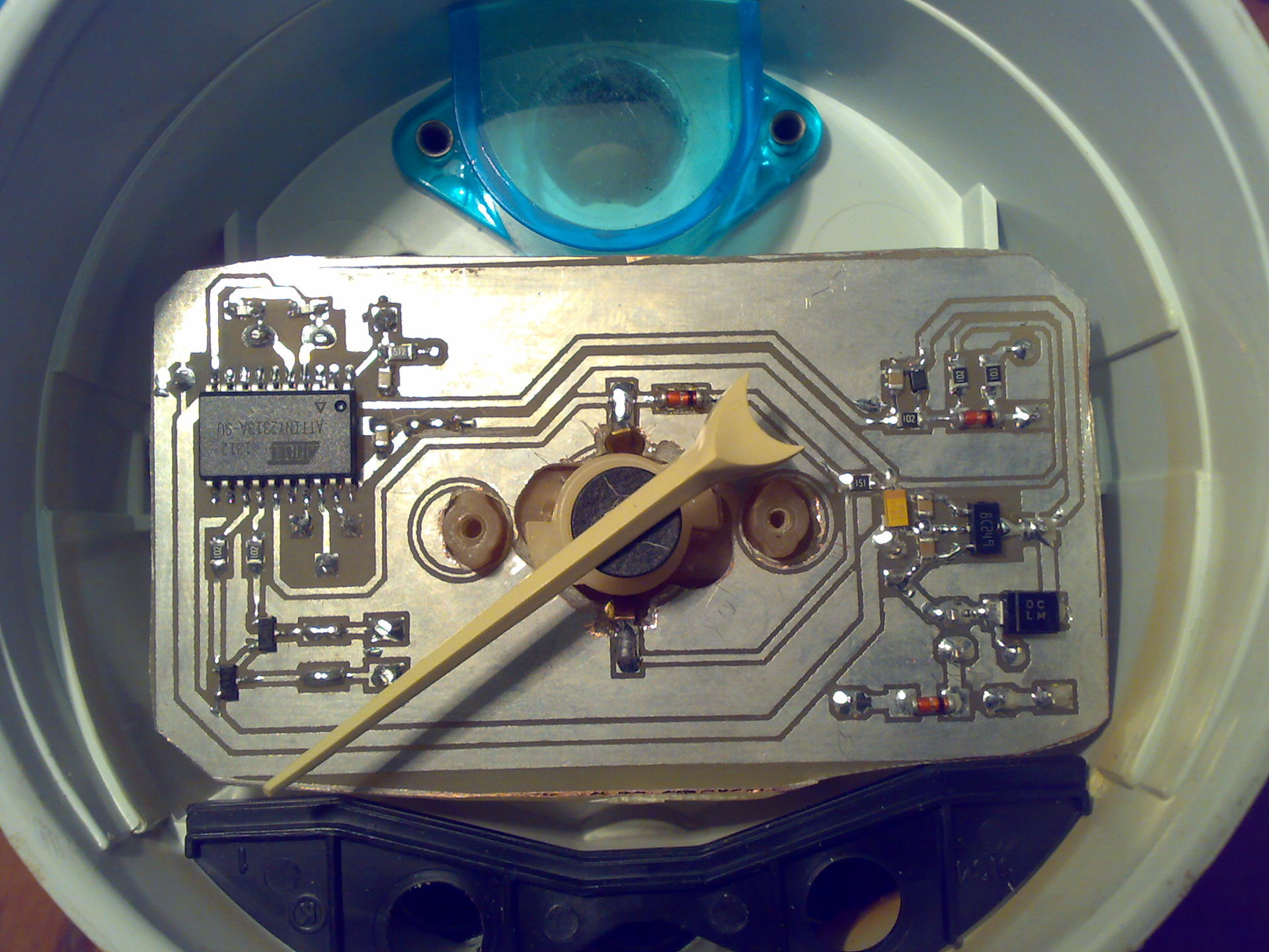
The assembled device without a dial now looks like this:
Soft
In fact, even before drawing the scheme, I quickly assembled the whole thing on a breadboard, taking the controller in the DIP package and immediately started waving the arrow))
In general, the software was a little more interesting than hard.
Let's start with the general architecture:
Timer 0 ticks with a frequency of 250 kHz, which means the period of the tick = 4 μs overflow interrupt occurs with a frequency of 250 kHz / 256 = 0.976 kHz
so an interrupt occurs once every 1024µs. It was possible to be confused and adjust this matter closer to one millisecond by updating the timer counter in the interrupt, but in this task there is nothing. Those. we can measure time with an accuracy of 4 μs, which is quite enough for a given accuracy of the device.
Timer 0 in our country not only counts time, but also sets checkboxes to run certain tasks at regular intervals.
We have two tasks. Giving INT0 interrupt to measure the period of the pulses at the input and change the position of the arrow.
Timer 1 ticks at 16 MHz, but since it is 16-bit and uses Phase and Frequency Correct PWM mode - the total PWM frequency is very small and is about 122 Hz. This is because the timer ticks up first and then down. But we have a true 16bit PWM and can very accurately steer the arrow! There are all the details in the datasheet.
The mechanics, by the way, turned out to be of disgusting quality, it was not realistic to move the needle smoothly due to the increased friction in the mechanism, which had to be started at least with lubricating gear oil. But these are details.
A table of the device readings correspondence with the corresponding value of the timer register in the PWM parrots was compiled.
In the source, this case is called GAUGE_TABLE and is rendered out of habit into a separate file.
It was further discovered that if you simply change the current in the ammeter circuit in one stroke in order, for example, to move the arrow 1000 forward, then it will make two or three or four oscillations in the area of the target mark, which was completely unacceptable and the customer paid special Attention. The fact is that these tachometers initially have such a problem and several times gazanuv to the beat of the oscillations can cause the arrow to swing with a significant amplitude (more than half of the scale!).
It was necessary to do something with it. My idea was to bring the arrow to the mark with a series of smaller steps, gradually approaching the goal. As a matter of fact, this part is the most interesting and useful for beginners, since requires some skill. After all, in dealing with a microcontroller, a call to log2 () in a cycle is, to put it mildly, not the most successful idea. By the same 8-bit architecture imposes even more restrictions. Well, about the "floating point" (floating point) and does need to forget. But all these difficulties, as always, lead only to a deeper understanding of the processes and calculations made by the processor.
For some reason, the text turns out to be more and more, but I just can’t stop at this point in more detail!
So, it is clear that we need a logarithmic progression. The step of changing the current in the milliammeter circuit should decrease as it approaches the target elevation. Resources worth their weight in gold, which means only the tabular method. Points, too, if possible at least.
Let's start with building a logarithmic table.
Everything is very simple: we run excel and with a few strokes of the mouse we get 50 values of the logarithm of base 2 for a sequence from 1 to 50. For clarity, we build a beautiful graph.
Perfectly! Exactly what is needed! But firstly - the points are as many as 50, and secondly all the floating point numbers. It does not suit us!
Therefore, we select 5 points from the existing array with a step of 10. We get something like this:
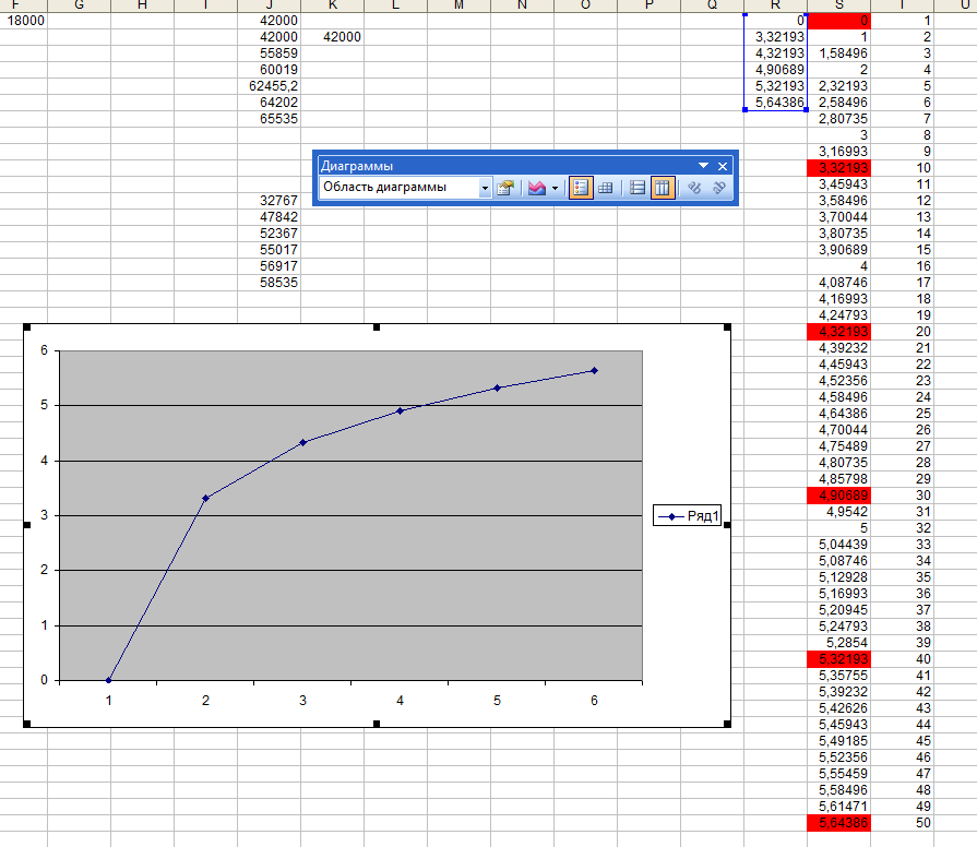
Already better. A consistent approach to the goal is still preserved, but the points are 10 times smaller.
Next you need to normalize the resulting set. Those. make it so that all values are in the range from 0 to 1. To do this, simply divide each element by 5.64385618977472 (the maximum value of our array).
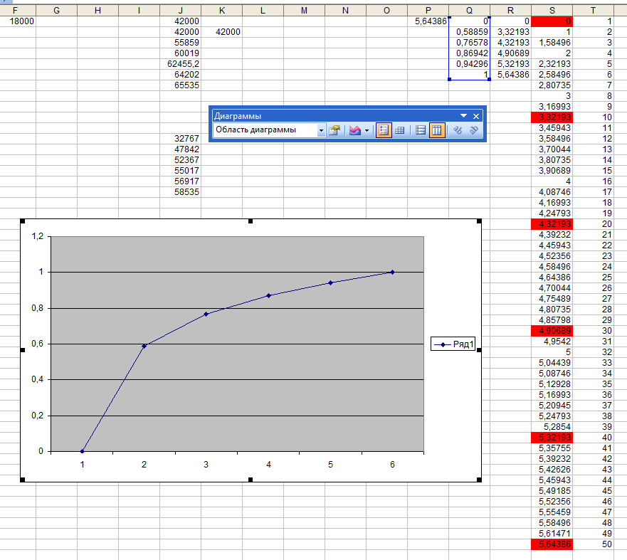
Thus, we get all the same logarithmic dependence, but already in a much more convenient form for further calculations. Such a table can already be applied quite easily, if not a point after zero. But with this, we are also pretty easy to understand.
Now I want us to take a beautiful value of 1024 per unit and again recalculate our table. Get

As you can see, the form of the graph has not changed, but the numbers now fit into the 16-bit range and there are no fractions.
In the source, the resulting array is called logtable []
The scaling factor (if you can call it that) 1024 appeared here not by chance and you need to understand very well why exactly 1024.
First, it is a power of two and it is chosen because expensive division and multiplication operations by power of two can be replaced with a cheap left / right shift and it would be foolish not to use this opportunity.
Secondly, the coefficient should be chosen based on the scale of the data to which it will be applied. In our case, these are the register values of the 16-bit timer, which controls the filling of the PWM. Experimentally it was revealed that the unsatisfactory oscillations of the arrow are detected even with its sharp displacement at 200 rpm. Those. if you need to move the arrow to more than ~ 200 rpm - smoothing is required. From the table GAUGE_TABLE it can be seen that neighboring cells differ on average by 4000 PWM parrots, which corresponds to approximately 500 rpm on the scale of the device. It is not difficult to estimate that in numbers the offset of the arrow by 200ob will be 4000 / 2.5 = 1600 PWM parrots.
Therefore, the scaling factor must be chosen so that firstly it is as large as possible, because otherwise we lose bits and accuracy, and secondly, as little as possible so as not to force us to switch from 16-bit variables to 32-bit variables and not to spend resources in vain. As a result, we choose the smallest degree of two, which is less than 1600 and provides sufficient accuracy. This will be 1024.
This moment is very important. I myself still sometimes have difficulty choosing the right coefficients and sizes of variables.
Well, then it really went. We find in the code the implementation of display_rpm () and see that the table GAUGE_TABLE [] is used to determine the specific value in the PWM parrots and the assumption that the scale between the adjacent marks is linear. To organize the current change according to the logarithmic law, an array of 5 points pwm_cuve [] is entered which contains a set of values, which must be sequentially subtracted or added (depending on the direction of arrow movement) from pwm_ocr1a_cur_val to make the arrow move smoothly and clearly.
each step is formed by multiplying the pwm_delta value by a factor from our logtable [] table;
Before multiplication, the value is pre-scaled by dividing by 1024.
The final target destination of the target_pwm arrow is written to pwm_cuve [] as it is, because due to problems with rounding and because the dimension of the variables is limited to 16 bits, the exact value as a result of the calculations will be formed there quite infrequently, so you have to ensure that the arrow will end its way at the given point.
In general, all of the above is essentially a single line.
Then, the main loop for the signal from the timer0 times in PWM_UPD_PERIOD raises the values from pwm_cuve and assigns them to the variable pwm_ocr1a_cur_val, the value of which in the interrupt will be assigned to the OCR1A register, which will immediately lead to a change in the PWM filling and change the current in the milliammeter circuit.
Here, in fact, almost all the tricks, except for the translation of the period presented in ticks of the timer in the rotational speed of the crankshaft, which is measured in revolutions per minute.
All this has been reduced to
We can talk about how this figure turned out or not talk next time, because even without that text it turned out quite a few and obviously not many read it even to this point.
Honestly speaking, several more “tricks” have been applied to the code in the code, which may seem to newbies not quite obvious. If someone wants to find out more about it - velkam in kamenty and HP.
A bit of video, as promised
Do not pay attention to the accuracy of the readings, the hand is not normally dressed + the dial is not twisted.
The movement of the arrow in increments of 1000 rpm in one jump.
Smooth current change
The point is clear that in reality there will be no jumps at 1000 rpm and those minor shooters, which, nevertheless, can be seen on the video will not become a problem. Just if you eliminate them, then you can lose great in the speed of the device and its readings will lag behind reality.
PS Not to say that the archive is completely govnokod, but yes, in some places it could be made more beautiful. Yes, I know that magic numbers are bad and yes, I could have been better. On the other hand, getting lost in the 200-line source is quite difficult, so in some places I allowed myself to do a bit of tinkering.
I just wanted to check in on the Habré for a long time, and writing any detailed article after a while after the project implementation becomes more and more difficult, so I decided that today they would “carry on from the fields”.
So the real code from a real device, assembled over a real period of 7 evenings, which tomorrow will be installed on a glorious VAZ 2108 car with a 21126 engine and I hope it will be a long time to please the owner, who agreed to pay 100 evergreens for my works.
But we all know that I did this whole journey not only and not so much for the sake of money. It's so nice when you created something and it even works!
In thearchive project Atmel studio and circuit + board in Altium designer. The board was made by the LUT method.
UPD: The archive was uploaded to a free file sharing service and therefore died suddenly. To store the archive on habrastorage, I embedded it in the photo of the tachometer without a dial (it is at the top of the article). In general, jpg need to save yourself and open winrar. You can even simply change the extension to zip.
UPD2: The scheme and the board are reworked, the pictures are updated, the archive is still in the picture.
UPD3 Archive is no longer inserted into pictures. Write in the LAN here or find me vk.com/trotskyi
See you again!
Vehicle check
The customer is very satisfied!
And when I saw this article and all the sources, including some photos of the board manufacturing process itself - said that his brain was blown up!
A week ago, I was approached by one person with a rather non-standard task - it was necessary to ensure the operation of the ancient tachometer TX-193 (VAZ 2106) with a
Under the cut photo, video, scheme, source, and a lot of text, telling about logarithms and how to properly scale the data and get rid of the comma.
')
Hard
Let's start with the device TX-193 . The mechanical part of the device is a milliammeter of a classical construction, with a permanent magnet and a moving coil, setting the arrow in motion.
For the development of the circuit, in essence, it was enough to know about the milliammeter only that, at a current of the order of 10 mA, the arrow deviates to the limit, and the winding resistance is approximately 180 Ohm. The ATtiny2313A controller from the renowned Atmel company, clocked from an external quartz crystal at 16 MHz, was chosen as the brain. The device is powered from the vehicle’s on-board network, which means according to GOST it must withstand a “beard” up to 100V and work stably in the range from 9-15V. Due to low consumption (several tens of milliamperes), it was decided to use a 7805 linear stabilizer with an inductive filter and a suppressor to protect against impulse noise. The device was going from what was at hand, so the powerful version 7805 is used in the finished product, although 78L05 per 100mA would be enough.
Milliammeter controller controls, of course, using PWM. For which the 16-bit timer was used in the Phase and Frequency Correct PWM mode.
Information about the frequency of rotation of the crankshaft is transmitted from the computer in the form of pulses from 0 - 12V. The active level is low. 2 pulses per crankshaft revolution. To capture these pulses, an external interrupt INT0 and the corresponding string from the RC filter, suspenders and protective diodes are used. In general, the circuitry of the device is quite typical and I was surprised to find that I had just written so much about it. But do not judge strictly, the first article after all.
The assembled device without a dial now looks like this:
Soft
In fact, even before drawing the scheme, I quickly assembled the whole thing on a breadboard, taking the controller in the DIP package and immediately started waving the arrow))
In general, the software was a little more interesting than hard.
Let's start with the general architecture:
Timer 0 ticks with a frequency of 250 kHz, which means the period of the tick = 4 μs overflow interrupt occurs with a frequency of 250 kHz / 256 = 0.976 kHz
so an interrupt occurs once every 1024µs. It was possible to be confused and adjust this matter closer to one millisecond by updating the timer counter in the interrupt, but in this task there is nothing. Those. we can measure time with an accuracy of 4 μs, which is quite enough for a given accuracy of the device.
Timer 0 in our country not only counts time, but also sets checkboxes to run certain tasks at regular intervals.
We have two tasks. Giving INT0 interrupt to measure the period of the pulses at the input and change the position of the arrow.
Timer 1 ticks at 16 MHz, but since it is 16-bit and uses Phase and Frequency Correct PWM mode - the total PWM frequency is very small and is about 122 Hz. This is because the timer ticks up first and then down. But we have a true 16bit PWM and can very accurately steer the arrow! There are all the details in the datasheet.
The mechanics, by the way, turned out to be of disgusting quality, it was not realistic to move the needle smoothly due to the increased friction in the mechanism, which had to be started at least with lubricating gear oil. But these are details.
A table of the device readings correspondence with the corresponding value of the timer register in the PWM parrots was compiled.
In the source, this case is called GAUGE_TABLE and is rendered out of habit into a separate file.
It was further discovered that if you simply change the current in the ammeter circuit in one stroke in order, for example, to move the arrow 1000 forward, then it will make two or three or four oscillations in the area of the target mark, which was completely unacceptable and the customer paid special Attention. The fact is that these tachometers initially have such a problem and several times gazanuv to the beat of the oscillations can cause the arrow to swing with a significant amplitude (more than half of the scale!).
It was necessary to do something with it. My idea was to bring the arrow to the mark with a series of smaller steps, gradually approaching the goal. As a matter of fact, this part is the most interesting and useful for beginners, since requires some skill. After all, in dealing with a microcontroller, a call to log2 () in a cycle is, to put it mildly, not the most successful idea. By the same 8-bit architecture imposes even more restrictions. Well, about the "floating point" (floating point) and does need to forget. But all these difficulties, as always, lead only to a deeper understanding of the processes and calculations made by the processor.
For some reason, the text turns out to be more and more, but I just can’t stop at this point in more detail!
So, it is clear that we need a logarithmic progression. The step of changing the current in the milliammeter circuit should decrease as it approaches the target elevation. Resources worth their weight in gold, which means only the tabular method. Points, too, if possible at least.
Let's start with building a logarithmic table.
Everything is very simple: we run excel and with a few strokes of the mouse we get 50 values of the logarithm of base 2 for a sequence from 1 to 50. For clarity, we build a beautiful graph.
Perfectly! Exactly what is needed! But firstly - the points are as many as 50, and secondly all the floating point numbers. It does not suit us!
Therefore, we select 5 points from the existing array with a step of 10. We get something like this:
Already better. A consistent approach to the goal is still preserved, but the points are 10 times smaller.
Next you need to normalize the resulting set. Those. make it so that all values are in the range from 0 to 1. To do this, simply divide each element by 5.64385618977472 (the maximum value of our array).
Thus, we get all the same logarithmic dependence, but already in a much more convenient form for further calculations. Such a table can already be applied quite easily, if not a point after zero. But with this, we are also pretty easy to understand.
Now I want us to take a beautiful value of 1024 per unit and again recalculate our table. Get
As you can see, the form of the graph has not changed, but the numbers now fit into the 16-bit range and there are no fractions.
In the source, the resulting array is called logtable []
The scaling factor (if you can call it that) 1024 appeared here not by chance and you need to understand very well why exactly 1024.
First, it is a power of two and it is chosen because expensive division and multiplication operations by power of two can be replaced with a cheap left / right shift and it would be foolish not to use this opportunity.
Secondly, the coefficient should be chosen based on the scale of the data to which it will be applied. In our case, these are the register values of the 16-bit timer, which controls the filling of the PWM. Experimentally it was revealed that the unsatisfactory oscillations of the arrow are detected even with its sharp displacement at 200 rpm. Those. if you need to move the arrow to more than ~ 200 rpm - smoothing is required. From the table GAUGE_TABLE it can be seen that neighboring cells differ on average by 4000 PWM parrots, which corresponds to approximately 500 rpm on the scale of the device. It is not difficult to estimate that in numbers the offset of the arrow by 200ob will be 4000 / 2.5 = 1600 PWM parrots.
Therefore, the scaling factor must be chosen so that firstly it is as large as possible, because otherwise we lose bits and accuracy, and secondly, as little as possible so as not to force us to switch from 16-bit variables to 32-bit variables and not to spend resources in vain. As a result, we choose the smallest degree of two, which is less than 1600 and provides sufficient accuracy. This will be 1024.
This moment is very important. I myself still sometimes have difficulty choosing the right coefficients and sizes of variables.
Well, then it really went. We find in the code the implementation of display_rpm () and see that the table GAUGE_TABLE [] is used to determine the specific value in the PWM parrots and the assumption that the scale between the adjacent marks is linear. To organize the current change according to the logarithmic law, an array of 5 points pwm_cuve [] is entered which contains a set of values, which must be sequentially subtracted or added (depending on the direction of arrow movement) from pwm_ocr1a_cur_val to make the arrow move smoothly and clearly.
each step is formed by multiplying the pwm_delta value by a factor from our logtable [] table;
Before multiplication, the value is pre-scaled by dividing by 1024.
The final target destination of the target_pwm arrow is written to pwm_cuve [] as it is, because due to problems with rounding and because the dimension of the variables is limited to 16 bits, the exact value as a result of the calculations will be formed there quite infrequently, so you have to ensure that the arrow will end its way at the given point.
In general, all of the above is essentially a single line.
pwm_cuve[ table_i ] = pwm_ocr1a_cur_val + (pwm_delta / LOG_TABLE_MAX * logtable[ table_i ]);Then, the main loop for the signal from the timer0 times in PWM_UPD_PERIOD raises the values from pwm_cuve and assigns them to the variable pwm_ocr1a_cur_val, the value of which in the interrupt will be assigned to the OCR1A register, which will immediately lead to a change in the PWM filling and change the current in the milliammeter circuit.
Here, in fact, almost all the tricks, except for the translation of the period presented in ticks of the timer in the rotational speed of the crankshaft, which is measured in revolutions per minute.
All this has been reduced to
engine_rpm = (uint16_t)(15000000UL / (uint32_t)rot_time);We can talk about how this figure turned out or not talk next time, because even without that text it turned out quite a few and obviously not many read it even to this point.
Honestly speaking, several more “tricks” have been applied to the code in the code, which may seem to newbies not quite obvious. If someone wants to find out more about it - velkam in kamenty and HP.
A bit of video, as promised
Do not pay attention to the accuracy of the readings, the hand is not normally dressed + the dial is not twisted.
The movement of the arrow in increments of 1000 rpm in one jump.
Smooth current change
The point is clear that in reality there will be no jumps at 1000 rpm and those minor shooters, which, nevertheless, can be seen on the video will not become a problem. Just if you eliminate them, then you can lose great in the speed of the device and its readings will lag behind reality.
PS Not to say that the archive is completely govnokod, but yes, in some places it could be made more beautiful. Yes, I know that magic numbers are bad and yes, I could have been better. On the other hand, getting lost in the 200-line source is quite difficult, so in some places I allowed myself to do a bit of tinkering.
I just wanted to check in on the Habré for a long time, and writing any detailed article after a while after the project implementation becomes more and more difficult, so I decided that today they would “carry on from the fields”.
So the real code from a real device, assembled over a real period of 7 evenings, which tomorrow will be installed on a glorious VAZ 2108 car with a 21126 engine and I hope it will be a long time to please the owner, who agreed to pay 100 evergreens for my works.
But we all know that I did this whole journey not only and not so much for the sake of money. It's so nice when you created something and it even works!
In the
UPD: The archive was uploaded to a free file sharing service and therefore died suddenly. To store the archive on habrastorage, I embedded it in the photo of the tachometer without a dial (it is at the top of the article). In general, jpg need to save yourself and open winrar. You can even simply change the extension to zip.
UPD2: The scheme and the board are reworked, the pictures are updated, the archive is still in the picture.
UPD3 Archive is no longer inserted into pictures. Write in the LAN here or find me vk.com/trotskyi
See you again!
Vehicle check
The customer is very satisfied!
And when I saw this article and all the sources, including some photos of the board manufacturing process itself - said that his brain was blown up!
Source: https://habr.com/ru/post/193892/
All Articles