"Achtung!", Or Monitor the status of the project assembly

To build a project, run tests and check the quality of the code, we (in the Mail.ru Calendar project) use Jenkins CI. Starting the assembly takes place immediately after pushing to the git repository (according to the hook) and, of course, I want to receive timely information about the failed builds. On the one hand, notifications by email seem to be enough, on the other hand, I want something more visible and fun.
About three or four years ago, when I was working on another project, for similar purposes a flashing light was bought working from a 220-volt network, and the MP709 module (USB-relay) of the notorious MasterKit company was purchased to control it. The decision was unsuccessful: firstly, this module did not have Linux support at that time (it was necessary to reverse the data exchange protocol and write its own “driver” under Linux), secondly, the location of the flasher limited the wires extending from the computer and from the socket. Anyway, the design was thrown into the far box and waited in the wings.
Recently, my hands once again itched, I wanted to do something interesting, but useless, and I remembered the flasher. Having rummaged in a heap of rubbish, I fished out from there: Arduino Nano - two pieces, the relay module - one piece, the MX-05V receiver - one piece and the MX-FS-03V transmitter - one piece. Thrusting the rest of the trash into the far corner of the balcony, waiting for my next hour, I proceeded to assemble the device.
Lyrical forgetting : Once, long ago, when I was young and I had a lot of time, I would take a couple of AVR microcontrollers, erase the board, solder the device, program it in assembly language ... And get the same at the exit. The pleasure from the process is greater, the result is the same.
Hardware
The scheme turned out to be extremely simple, since in our time a huge number of various electronic modules, constructors and units make it possible to assemble an electronic device to anyone who has never taken a soldering iron in his hands and has not studied circuit design and programming. Transmitter (Arduino Nano + MX-FS-03V)
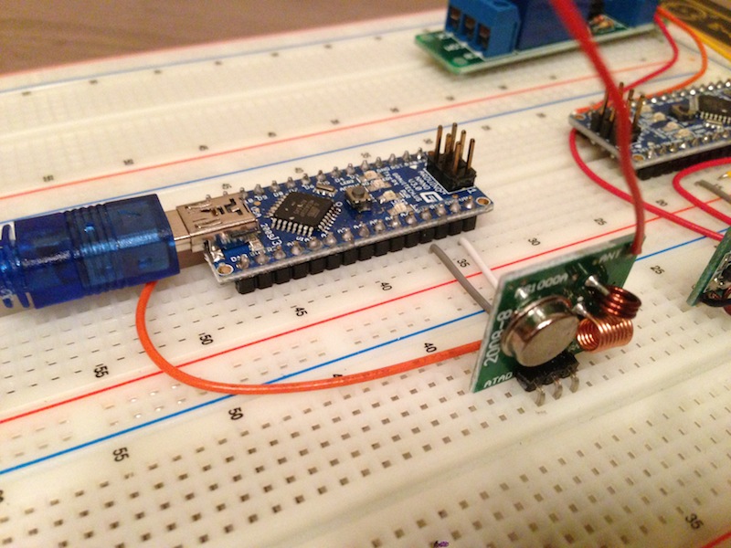
Receiver (MX-05V + Arduino Nano + Relay Module):

The principle of operation is even simpler: the Arduino connects to the computer’s USB port and listens to commands via a serial interface. If the command is valid, it will be transmitted via a radio transmitter. In the second block, the other Arduino listens to the receiver and when a command arrives, it either turns the relay on or off. Everything. No feedback, no checks (checksums), no logic.
The transmitter program is as follows:
#include <VirtualWire.h>
int ledPin = 13 ; // pin with led on it
')
char incoming_byte ; // a buffer to store the incoming messages
char input_data [ 12 ] ; // the size of the message
int input_size = 0 ; // counter, just counter
void setup ( ) {
// setup led pin
pinMode ( ledPin, OUTPUT ) ;
digitalWrite ( ledPin, LOW ) ;
// initialize serial (9600 bps)
Serial. begin ( 9600 ) ;
Serial. println ( "Ready for achtung" ) ;
// initialize the IO and ISR
vw_set_ptt_inverted ( true ) ; // required for DR3100
vw_setup ( 1200 ) ; // bits per sec
}
void loop ( ) {
while ( Serial. available ( ) > 0 ) {
incoming_byte = Serial. read ( ) ; // read the incoming byte
if ( incoming_byte == 'n' ) {
input_data [ input_size ++ ] = 0 ;
if ( strncmp ( input_data, "Achtung ON" , 10 ) == 0 || strncmp ( input_data, "Achtung OFF" , 11 ) == 0 ) {
digitalWrite ( ledPin, HIGH ) ;
vw_send ( ( uint8_t * ) input_data, input_size ) ;
vw_wait_tx ( ) ; // wait until the whole message is gone
digitalWrite ( ledPin, LOW ) ;
Serial. println ( "OK" ) ;
} else {
Serial. println ( "FAIL" ) ;
}
while ( input_size - > = 0 ) {
input_data [ input_size ] = 0 ;
}
input_size = 0 ; // reset counter
} else {
if ( input_size <= 11 ) {
input_data [ input_size ] = incoming_byte ;
}
input_size ++ ;
}
}
}
Receiver program:
#include <VirtualWire.h>
int ledPin = 13 ; // pin with led on it
int relayPin = 3 ; // pin with relay on it
byte input_data [ VW_MAX_MESSAGE_LEN ] ; // a buffer to store the incoming messages
byte input_size = VW_MAX_MESSAGE_LEN ; // the size of the message
void setup ( ) {
// setup led pin
pinMode ( ledPin, OUTPUT ) ;
digitalWrite ( ledPin, LOW ) ;
// setup relay pin
pinMode ( relayPin, OUTPUT ) ;
digitalWrite ( relayPin, HIGH ) ;
// initialize the IO and ISR
vw_set_ptt_inverted ( true ) ; // required for DR3100
vw_setup ( 1200 ) ; // bits per sec
vw_rx_start ( ) ; // start the receiver
}
void loop ( ) {
// check if we have some data to process
if ( vw_get_message ( input_data, & input_size ) ) {
digitalWrite ( ledPin, HIGH ) ;
if ( strncmp ( ( char * ) input_data, "Achtung ON" , 10 ) == 0 ) {
digitalWrite ( relayPin, LOW ) ; // achtung! turn relay on
} else if ( strncmp ( ( char * ) input_data, "Achtung OFF" , 11 ) == 0 ) {
digitalWrite ( relayPin, HIGH ) ; // turn relay off
} else {
delay ( 1000 ) ;
}
digitalWrite ( ledPin, LOW ) ;
}
}
As you can see, everything is extremely simple. We connect the microcontrollers, flash, respectively, the receiver and the transmitter using the built-in program in the Arduino bootloader, run the “Serial Monitor” connected to the transmitter, and send the on / off relay commands, as well as invalid commands (for testing):
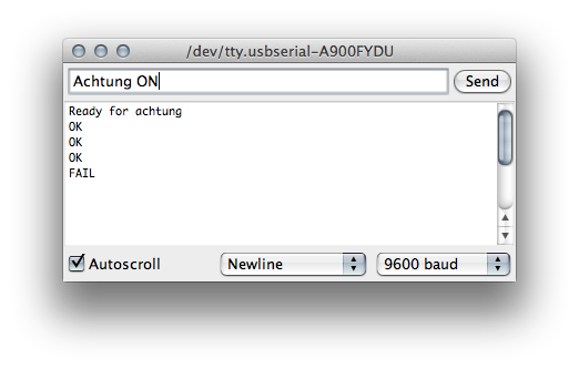
The relay turns on and off, everything works, everything is fine.
It's time to disassemble the flasher and see where we place the receiver and the relay:
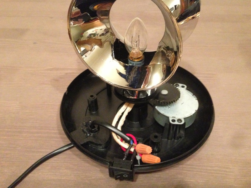
We see that inside a lot of space. We proceed to the assembly of the device, but first it is necessary to understand the power supply of the receiver.
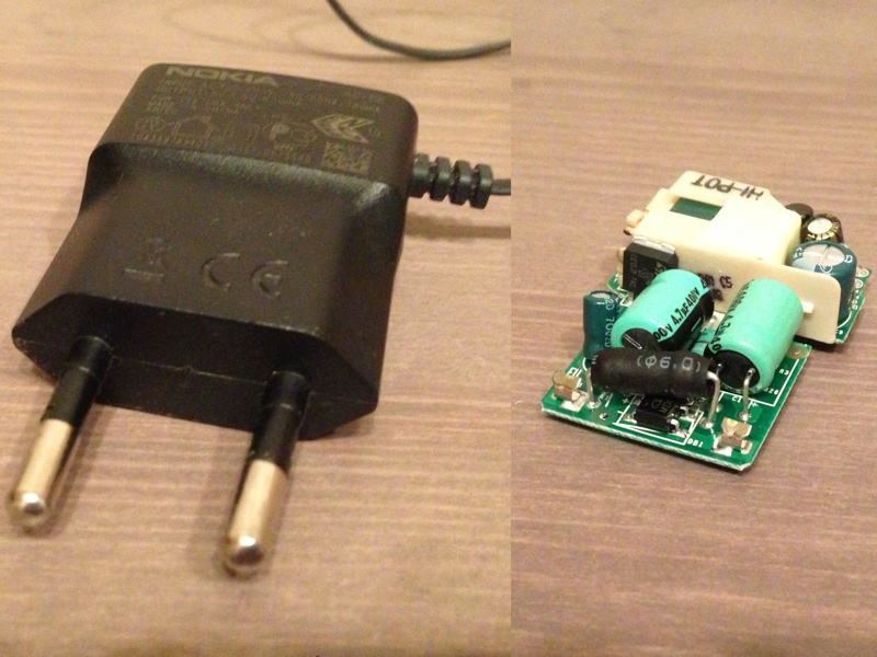
I did it simply: I took an old, unnecessary, power supply from a Nokia cell phone, took it apart and got a small fee that could power our receiver from 220 volts. I have to note that the process of removing the board from the case turned out to be an incredibly difficult task. The body is made of high quality plastic. Nevertheless, I managed it:
We collect flasher with our receiver and power supply:

We make sure that everything works: we turn on the device in the network and send the command “Achtung ON” via the “Serial Monitor” to the transmitter. The relay is clicked, the light bulb is on fire, the engine is spinning, hurray! We send the command “Achtung OFF” - everything stopped. The flasher is working. It remains only to attach the boards with screws and Chinese hot melt and assemble the entire structure in its original form.
With the transmitter, I decided not to stand on ceremony and just soldered everything together:

In the future I plan to pack it all in a beautiful case.
Software
In order to send commands from the computer to the transmitter, we write a simple script:
#! / usr / bin / env python
"" "
Send 'ON' or 'OFF' command to achtung transmitter.
"" "
from __future__ import print_function
import os
import sys
import serial
if __name__ == '__main__' :
if len ( sys . argv ) ! = 3 :
print ( "Usage: achtung / dev / ttyXX <ON | OFF>" )
sys . exit ( 1 )
tty = sys . argv [ 1 ]
if not os . path . exists ( tty ) :
print ( "ERROR: device '% s' is not exists" % tty )
sys . exit ( 1 )
command = sys . argv [ 2 ]
if command not in ( 'ON' , 'OFF' ) :
print ( "ERROR: unknown command '% s'" % command )
sys . exit ( 1 )
transmitter = serial. Serial ( tty , 9600 )
if transmitter. readline ( ) . strip ( ) ! = 'Ready for achtung' :
print ( "ERROR: device is not initialized" )
sys . exit ( 1 )
transmitter. write ( "Achtung% sn" % command )
result = transmitter. readline ( ) . strip ( )
if result ! = 'OK' :
print ( "ERROR: device response is not OK" )
sys . exit ( 1 )
For the script to work, you must install the dependency - the pyserial module:
pip install pyserialWe start, we enjoy the switched on / off flasher:
  python achtung.py /dev/tty.usbserial-A900FYDU ON
     python achtung.py /dev/tty.usbserial-A900FYDU OFF
To obtain the status of assemblies in Jenkins CI, it is best to use the jenkinsapi module, in which case the script will turn out to be elementary. Install dependencies:
pip install jenkinsapiThe script itself:
#! / usr / bin / env python
"" "
Check for Jenkins jobs status and run alarm if job is not OK.
"" "
import os
import sys
import time
import serial
from jenkinsapi. jenkins import Jenkins
from jenkinsapi. exceptions import JenkinsAPIException
URL = 'http://jenkins.example.ru/'
USERNAME = 'jenkins'
PASSWORD = 'secret'
JOBS = [ 'build' , 'test' , 'lint' ]
TTY = '/dev/tty.usbserial-A900FYDU'
def job_failed ( connect, job_name ) :
"" "
Returns boolean job status (True - success, False - fail).
"" "
if job_name not in connect:
return true
last_build = connect [ job_name ] . get_last_build ( )
if last_build. is_running ( ) :
return false
build_status = last_build. get_status ( )
if build_status in ( 'FAIL' , 'FAILED' , 'FAILURE' , 'ERROR' , 'REGRESSION' ) :
return true
return false
def send_to_transmitter ( device, command ) :
"" "
Send command to device and die on error.
"" "
device. write ( "Achtung% sn" % command )
result = device. readline ( ) . strip ( )
if result ! = 'OK' :
print ( "ERROR: device response is not OK" )
sys . exit ( 1 )
if __name__ == '__main__' :
if not os . path . exists ( tty ) :
print ( "ERROR: device '% s' is not exists" % TTY )
sys . exit ( 1 )
try :
connect = Jenkins ( URL, USERNAME, PASSWORD )
if any ( job_failed ( connect, job_name ) for job_name in JOBS ) :
transmitter = serial. Serial ( TTY, 9600 )
if transmitter. readline ( ) . strip ( ) ! = 'Ready for achtung' :
print ( "ERROR: device is not initialized" )
sys . exit ( 1 )
send_to_transmitter ( transmitter, 'ON' )
time . sleep ( 5 )
send_to_transmitter ( transmitter, 'OFF' )
except JenkinsAPIException:
sys . exit ( 1 )
The launched script connects to Jenkins, gets the status of these tasks and, if one of them fails, turns on the flasher for five seconds (this is done so that the blinking does not irritate, but made it clear that the build failed). The script runs in the crown every minute from 11:00 to 20:00 on weekdays (the working time of our employees) - it makes no sense to turn on the flasher in the night or on the weekend.
Of course, it was possible not to pour the results of the assemblies, but to configure Jenkins so that if an unsuccessful assembly he initiated the inclusion of the flashing lights, but the security requirements in our company exclude this possibility: any connections from the network to the servers to the office network are strictly prohibited.
Profit!
Everything is set up, it works, and it pleases all developers (except the one that sfailil build) with cheerful blinking at the most opportune moment.
Sources: https://github.com/dreadatour/jenkins-achtung .
Update : video of the device:
Source: https://habr.com/ru/post/193606/
All Articles