Welding of optical fibers. Part 1: cables and their cutting, optical tools, couplings and crosses, connectors and adapters
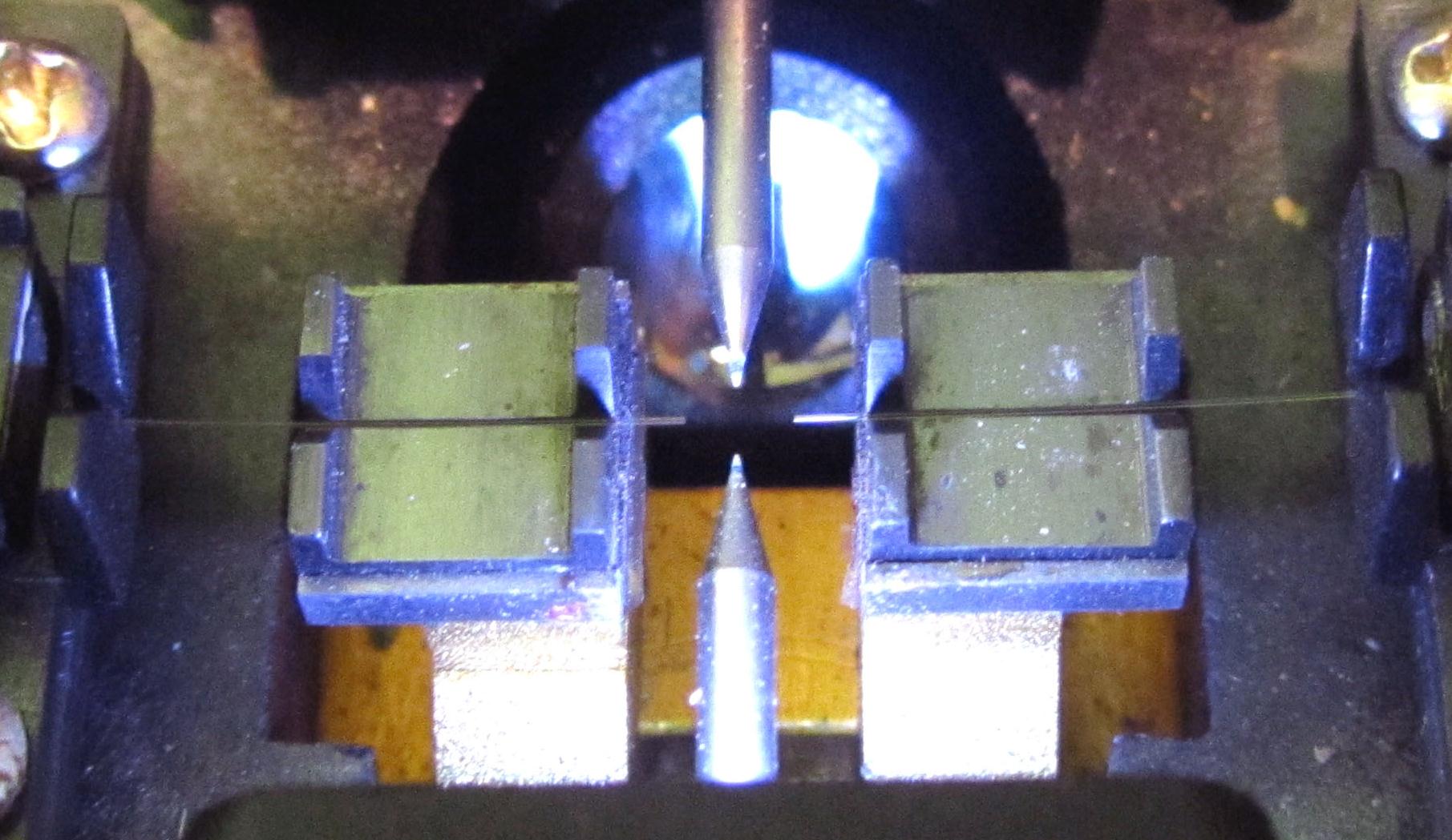
The fibers are charged in the welding machine
Hello, readers Habra! Everyone heard about optical fibers and cables. There is no need to tell where and why optics are used. Many of you are faced with it at work, someone is developing trunk networks , someone is working with optical multiplexers . However, I have not met a story about optical cables, couplings, crosses, about the technology of splicing optical fibers and cables. I am an optical fiber solder, and in this (my first) post I would like to tell and show you how it all happens, and I will often be distracted in my story by other related things. I will rely mainly on my experience, so I fully admit that someone will say "this is not entirely correct", "this is uncanonical here."
The material turned out a lot, so it became necessary to break the topic into parts.
In this first part you will read about the device and cable cutting, about the optical instrument, about preparing the fibers for welding. In other parts, if the topic turns out to be interesting for you, I will tell you about the methods and show on video the very process of splicing the optical fibers themselves, about the fundamentals and some nuances of measurements on optics, touch upon the topic of welding machines and reflectometers and other measuring devices, show spiderman jobs ( roofs, basements, attics, hatches and other fields with offices), I’ll tell you a little about cable fixing, decoupling schemes, and equipment placement in telecommunication racks and drawers. This is certainly useful to those who are going to become a welder. I added all this to a large number of pictures (I apologize in advance for the paint-quality) and photos.
Caution, a lot of pictures and text.
Part 2 is here .
Introduction
First, a few words about me and my work.
I work as an optics solder. He started with a telephone operator and installer, then worked in an emergency crew on servicing mainline optics. Now I work in an organization that takes general contracts for the construction of facilities and communication lines from various companies. A typical construction project is a cable line connecting several GSM base station containers. Or, for example, several FTTB rings. Or what is smaller - for example, laying a cable between two server rooms on different floors of a building and unwelding on the ends of a cross-over cable.
If the tender is won, suitable subcontractors are being sought who perform the work (design and survey and construction and installation). In some regions, these are our subsidiaries, some have their own equipment and resources, and some hire independent companies. But on our shoulders, control rests primarily, eliminating the jambs of subcontractors and various force majeure, all sorts of agreements with land owners and administrations, sometimes drawing up as-built documentation on the constructed facility (documentation — mainly RD 45.156-2000; here is a list, plus a section with different licenses is added) and so on. Often, you need to work with optics: weld or digest an optical coupling or cross, eliminate the consequences of a support or a tree falling on the cable, carry out the input control of the cable drum, remove the reflectograms of the site and so on. It is these tasks that I perform. Well, along the way, when there are no problems in optics - other tasks: from loading and assembly through courier-delivery to copy and paper works. :)
')
Optical cable, its types and interiors
So what is an optical cable? Cables are different.

By construction - from the simplest (shell, plastic tubules under it, the fibers themselves) to super-folded (multiple layers, two-level armor - for example, underwater trans-oceanic cables).
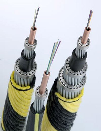
At the place of use - for outdoor and indoor installation (the latter are rare and usually in high-end data centers, where everything should be perfectly correct and beautiful). Under the terms of the installation - for suspension (with Kevlar or cable), for soil (with iron wire armor), for installation in cable ducts (with corrugated metal armor), underwater (complex, ultra-protective multi-layer construction), for suspension on power lines (besides the transfer of information, they play the role of a lightning protection cable). In my practice, the most common cables for hanging on poles (with Kevlar) and for laying in the ground (with armor). Less likely to come across with a rope and a corrugated dresser. Another common cable is that there is essentially a thin paired optical patch cord (the yellow sheath is single-mode and the orange is multi-mode, a bit of Kevlar and one fiber; two sheaths are paired). Other optical cables (without protection, underwater, for laying in rooms) are exotic. Almost all the cables I work with are designed as in the picture below.
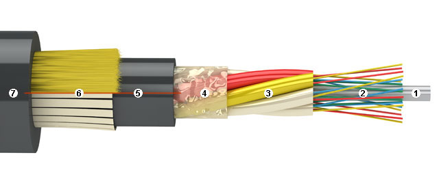
1 - the central power element (in other words, fiberglass rods, although it may be a wire in a plastic sheath). Serves for centering the tube modules, stiffening the entire cable. For him also often fix the cable in the coupling / cross, clamping under the screw. With a strong bend of the cable has a dastardly ability to break, breaking along the way and modules with a part of the fibers. More advanced cable designs contain this bar, clad in a plastic sheath: then it will be harder to break and the cable will cause less damage when broken. The bar can be the same as in the picture, and quite thin. The tip of such a bar is an excellent abrasive tool for fine work: for example, clean the relay contacts or a section of the copper part for soldering. If you burn it a couple of centimeters, you get a nice soft brush. :)
2 - the optical fibers themselves (in the figure - in lacquer insulation). Those very thinnest fibers are light guides, for the sake of which everything is being started. The article will deal only with glass fibers, although there are plastic somewhere in nature, but they are very exotic, they do not boil optics welding machines (only mechanical connections) and are only suitable at very small distances and I personally have not encountered them . Optical fibers are singlemode and multimode, I met only with singlemode, since multimode is a less common technology, can only be used for short distances and in many cases is perfectly replaced by singlemode. The fiber consists of a glass "shell" of glass with certain impurities (I will not dwell on chemistry and crystallography, since I do not own the topic). Without varnish, the fiber has a thickness of 125 microns (slightly thicker than the hair), and in the center of it there is a core with a diameter of 9 microns made of ultrapure glass with a different composition and with a refractive index slightly different from the shell. It is in the core that radiation is propagated (due to the effect of total reflection at the “core-shell” boundary). Finally, on top of the 125-micron cylinder of the “shell” is covered with another shell - of a special lacquer (transparent or colored - for color marking of the fibers), which EMNIP is also two-layer. It protects the fiber from moderate damage (without the lacquer, the fiber bends, but it is bad and easy to break, the fiber simply crumbles from a mobile phone that was accidentally placed on it; in lacquer you can easily wrap it around the pencil and pull it pretty hard). It happens that the cable span sagged on some fibers: the shells were torn (burned, cut), Kevlar burst, the central bar broke, and some 16 or 32 125 micron glass fibers can hold the weight of the cable span and wind loads for weeks! However, even in fiber lacquer, you can easily damage it, so in the work of the solder, the most important thing is meticulousness and accuracy. One awkward movement can spoil the results of a whole day of work or, if you are not particularly lucky and there is no redundancy, drop the trunk connection for a long time (if, digging into the "combat" trunk coupling, break the fiber with DWDM under the spine at the cable output).
Fibers come in many varieties: normal (SMF or just SM), with shifted dispersion (DSF or just DS), with non-zero shifted dispersion (NZDSF, NZDS or NZ). Externally, they can not be distinguished, the difference is in the chemical / crystalline composition and, possibly, in the geometry of the central core and in the smoothness of the boundary between it and the shell (unfortunately, it did not clarify this question to the end for itself). Dispersion in optical fibers is a harsh and difficult to understand thing, worthy of a separate article, so I will explain it more simply - a signal with distorted dispersion can transmit a signal without distortion any further than a simple one. In practice, the solders know two types: simple and “with displaced”. The cable often allocates the first module under the “displaced”, and the rest - under the simple fibers. It is possible to dock the “displacement” and simple fiber, but it is undesirable, it causes one interesting effect, which I will discuss in another part, about measurements.
3 - plastic tubular modules in which fibers float in the hydrophobe.
Cable, cut to modules
They easily break (more precisely, they are suddenly bent) when bending like telescopic antennas from household receivers, breaking fibers inside. Sometimes a module is just one (in the form of a thick tube), and there is a bundle of fibers in it, but in this case you need too many different colors for marking the fibers, so usually there are several modules, each of which has from 4 to 12 fibers. There is no single standard for coloring and the number of modules / fibers, each manufacturer does it in its own way, displaying everything in the cable passport. The passport is attached to the cable drum and is usually stapled to a tree right inside the drum with a stapler.
Cable passport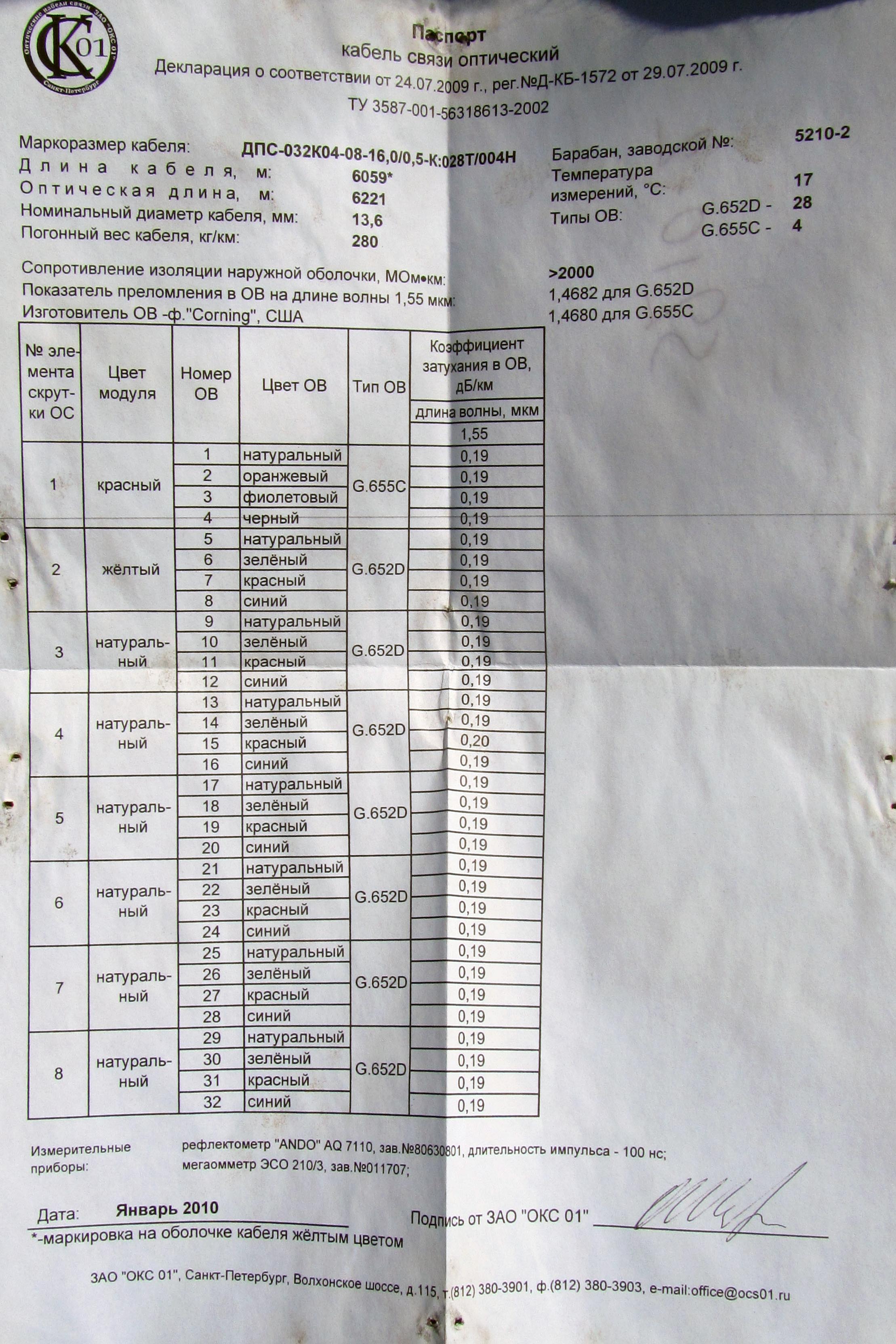
Typical cable passport. I apologize for the quality.
Typical cable passport. I apologize for the quality.
However, it is hoped that, say, the DPS cable from the manufacturers of Transvoc and Beltelekabel will still be the same in configuration. But you still need to look at the passport to the cable, where the detailed colors are always indicated and what type of fiber in which modules lie. The minimum capacity of an “adult” cable that I met was 8 fibers, the maximum capacity was 96. Usually 32, 48, 64. Of the whole cable, 1 or 2 modules are used, then black dummy plugs are inserted instead of the remaining modules (so that cable has not changed).
4 - film wrapping modules. It plays minor roles - damping, reducing friction inside the cable, additional protection against moisture, keeping the hydrophobic in the space between the modules and, possibly, something else. It is often additionally tightened with threads crosswise and moistened on both sides with a hydrophobic gel.
5 - thin inner sheath of polyethylene. Dop.protection against moisture, a protective layer between Kevlar / armor and modules. May be absent.
6 - Kevlar threads or armor . In the figure, armor is made of rectangular bars, but where it is more often found from round wires (in imported cables there are steel wires and difficult to bite even with cable ties, in domestic ones, usually from nails). Armor can be in the form of fiberglass rods, the same as the central element, but in practice it has not been encountered with such. Kevlar is needed so that the cable can withstand a large tensile force and not be heavy. It is also often used instead of a cable where there should be no metal in the cable in order to avoid interference (for example, if the cable hangs along the railway, where the contact wire from 27.5 kV is near). Typical values of permissible tensile stress for a cable with Kevlar are 6 ... 9 kilonewtons, this allows one to withstand a large span under wind load. When cutting Kevlar terribly tupit cutting tool. :) Therefore, it is better to cut it or special scissors with ceramic blades, or bite off the trosokusami, which I do.
As for the armor - it is designed to protect the underground cable lying directly in the ground, without protection in the form of a plastic pipe, cable ducts, etc. However, it can only protect the armor from a shovel, the excavator still tears any cables. Therefore, the underground cable is laid in the ground for 1 m 20 cm, and above it, at a depth of 60 cm, a yellow or orange signal tape with a “Caution! Do not dig! Below the cable ”, as well as along the route, there are columns, warning signs and notices. But still dig and tear.
7 - outer thick sheath of polyethylene . Accepts the first all the burden when laying and operating the cable. Polyethylene is soft, so it is easy to cut it with an inaccurate tightening of the cable. It happens that when laying the underground cable, the contractor will break this shell up to several meters before armor and will not notice that moisture gets into the cable despite the hydrophobic, and then when the outer sheath is tested with a megohmmeter, the megohmmeter shows low resistance (high leakage current) .
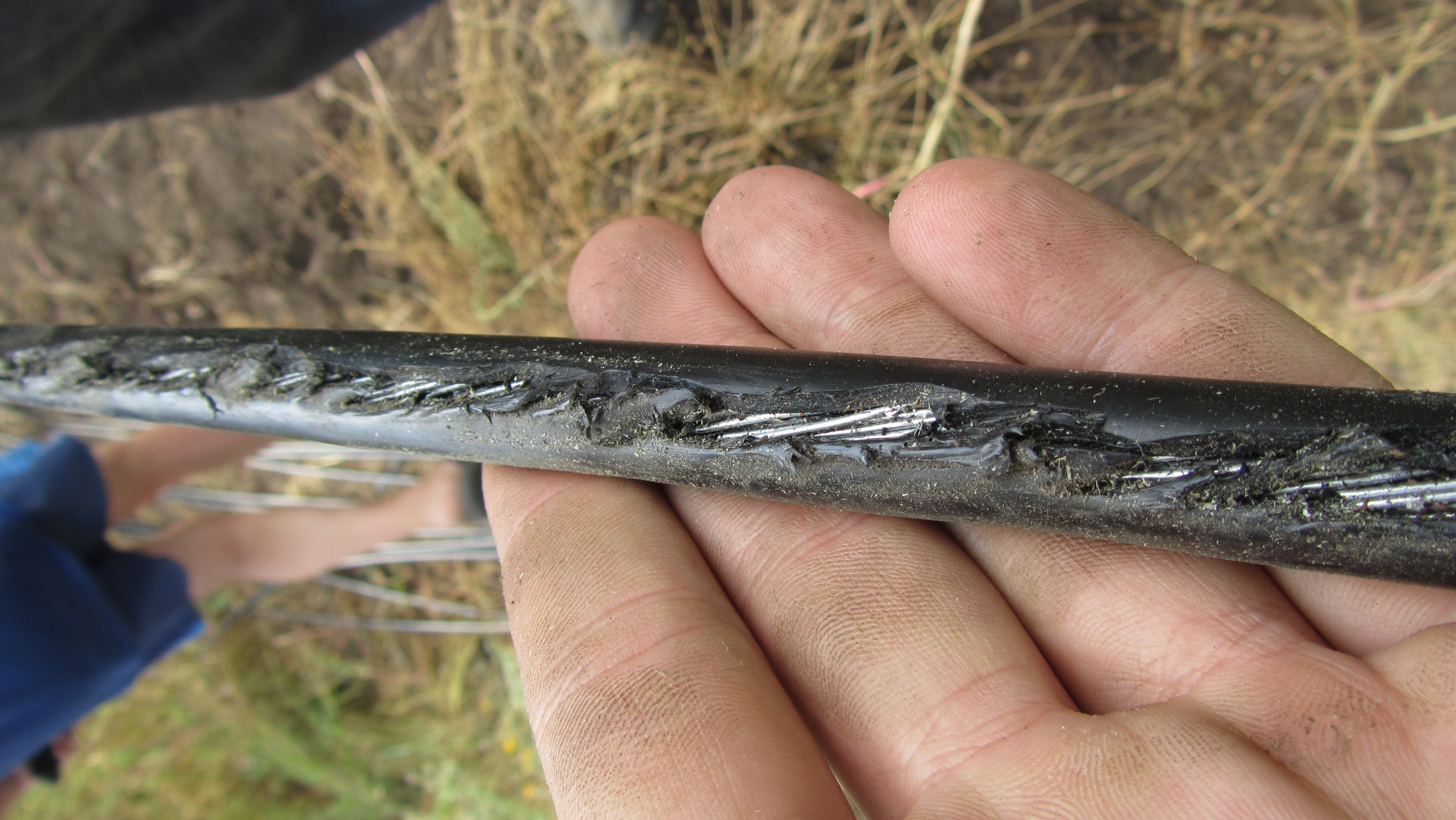
If the hanging cable touches a concrete pole or a tree, polyethylene can also quickly wipe down to the fibers.
A polyethylene film and some hydrophobic gel may be present between the outer shell and the armor.
They are bought from companies such as Corning, OFS, Sumitomo, Fujikura, and others. But they make cables in Russia and Belarus! Moreover, in my practice, 95% of the cables I worked with are from Russia or Belarus. At the same time imported fiber is laid in the cable. Offhand from my experience I recall such cable manufacturers as Beltelekabel, MosKabel Fujikura (ICF), Eurocable, Transvoc, Integra-cable, OFS Svyazstroy-1, Saransk-cable, Incab. There are others. Of the imported cables, only Siemens remained in the memory. Subjectively, all cables are similar in construction and materials, and the quality is not particularly different.
Here, actually, I told about the device of optical cables. Go ahead.
Cable cutting: the necessary tools and techniques
For cable cutting, as for welding, a number of specific tools are required. A typical set of fitter-solder is a suitcase with NIM-25 tools, it contains all the necessary strippers, cable hooks, screwdrivers, side cutters, pliers, mock-up knife and other tools, as well as a pump or vial for alcohol, hydrophobic solvent “D- Gel, non-woven, lint-free napkins, electrical tape, self-adhesive digital markers for cables and modules, and other consumables.

After completing the consumables (couplers, worm clamps, etc.) and some auxiliary tools it is quite enough to work with optics. There are also other sets, richer and poorer in terms of configuration ("BAT-E" and "BAT-C"). The weak point of most of the sets is the low quality of the “aluminum type” case, which only looks beautiful, but in fact consists of thin fiberboard, plastered / textured corrugated foil, and aluminum corners on rivets. It does not stand for long in the field and urban conditions, and it has to be repaired and strengthened. In my case, the case stood for 3 years and, being completely worn out, pulled together with corners and bolts, with a “collective farm” organizer instead of a native one, it was replaced with an ordinary plastic tool box. Some tools and materials from the standard kit may be of poor quality. I personally did not need some tools. Some of the 3 years of work have already been replaced. As the use of "branded" consumables, some are replaced by "assistants" without prejudice to the quality of work. Thus, the factory nonwoven lint-free wipes for wiping the fibers are easily replaced with toilet paper of the “mouth” type. :) The main thing is to be non-flavored. Instead of expensive (about 800 r / liter) D-Gel, if the work goes outdoors, you can use gasoline AI-92.
When cutting cables, it is important to withstand the lengths of the cable elements in accordance with the requirement of the coupling instruction: so, in one case, it may be necessary to leave a long power element to secure it in the coupling / cross, in the other case it is not required; in one case, a pigtail is woven from the Kevlar cable and clamped under the screw; in the other case, Kevlar is cut off. It all depends on the specific coupling and the specific cable.
Consider the cutting of the most typical cable:
a) Before cutting a cable that has been wet for a long time or without a waterproofed end, cut about 1 meter of the cable with a hacksaw (if it allows for it), as long-term exposure to moisture adversely affects the optical fiber (may become cloudy) and other cable elements. Kevlar threads in a cable are an excellent capillary that can “pump” water tens of meters into itself, which is fraught with consequences if, for example, high voltage wires go in parallel with the cable: currents can be walked through the wet Kevlar, the water is evaporated, it is crushed from the inside the outer sheath, the cable goes bubbles and through the bubbles from the rain gets a new moisture.
b) If there is a separate cable for suspension in the cable design (when the cable in cross section has the shape of the figure “8”, where the cable is in the lower part, in the upper cable) it is bitten out by cable ties and cut off with a knife. When cutting the cable, it is important not to damage the cable.
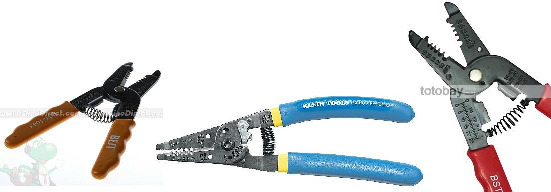
c) To remove the outer jacket of the cable, use the appropriate knife-stripper. BAT-25 is usually completed with a knife “Kabifix” as in the photo below, however, you can use a knife-stripper for electrical cables, which is with a long handle.

Such a knife-stripper has a rotating in all directions blade that can be adjusted in length in accordance with the thickness of the outer sheath of the cable, and a clamping element for holding onto the cable. Important: if you have to cut the cables of different brands, then before cutting the new cable you need to try the knife at the tip and, if you cut the modules too deeply and damaged the modules, you need to tighten the blade in short. Worse than ever, when the coupling is already welded, and suddenly when laying the fibers one fiber suddenly “jumps out” of the cable, because when cutting the knife hooked the module and broke this fiber: all work is for nothing.
A knife-stripper for removing the outer cable sheath is made a circular cut on the cable, and then from it - two parallel cuts on opposite sides of the cable towards the end of the cable so that the outer sheath breaks into two halves.
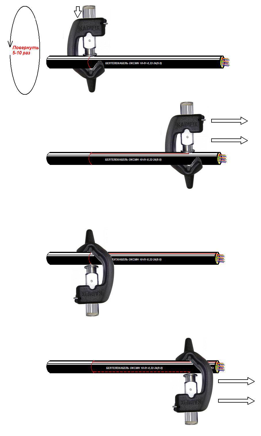
It is important to correctly set the blade length of the stripper knife, since if the blade is too short, the outer shell will not easily split into two halves and will have to be ripped off with pliers for a long time, and in the case of a long blade you can damage the modules deep in the cable or dull the rotating blade about the armor.
d) If the cable is self-supporting with Kevlar, then Kevlar is cut by cable ties or scissors with special ceramic blades.
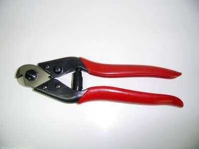
Trosokusy
Kevlar should not be cut with a knife or simple scissors without ceramic linings on the blades, since Kevlar quickly taps metal cutting tools. Depending on the design of the coupling, it may be necessary to leave a part of Kevlar of a certain length for fixing, this will be explained in the installation instructions for the coupling.
If the cable is intended for installation in a telephone conduit and from armor contains only metal corrugation (so that rats are not gnawed), it can be cut longitudinally with a special tool (reinforced with a plow knife). , to increase the metal fatigue in the place of the risks and the appearance of cracks, after which you can remove some of the corrugations, bite the modules and tighten the corrugation. This cutting should be done especially carefully, since it is easy to damage the modules and fibers: the corrugation is not too strong, it can be flushed in the place where it is picked with tools, and when they are pulled from the fibers, sharp edges in the place of breakage can penetrate the modules and damage the fibers. Cable with corrugation is not the most convenient for cutting.
If the cable is armored with round wires, they should be bitten off by small lines, 2-4 wires each. Side cutters get longer and harder, especially if the wire is steel. For some couplings, a certain length of armor is required for fixation, and armor (including corrugated one) is often required to be grounded.
e) For the inner, thinner sheath present in some cables (for example, self-supporting with Kevlar), you should use a separate, pre-configured knife stripper (you can use the same one as for removing the outer sheath of the cable) so as not to knock down the length of the knife every time you cut the cable.In this case, it is especially important to correctly set the blade length in the knife stripper, it will be less than in the stripper to remove the outer cable sheath, since the inner sheath is significantly thinner, and immediately below it the modules with fibers. With a certain skill, you can use a regular breadboard knife to remove the inner shell, making them a longitudinal section, but there is a significant risk of damage to the modules. You can also use a stripper for coax cutting.
e) With the modules with the help of napkins and D-Gel / gasoline, threads, plastic film and other auxiliary elements are removed. Threads can be twisted one by one, you can rip off with a special sharp "pluzkovym" hook (may be included in the design of some knives-strippers to remove the shell). To remove the hydrophobic solvent D-Gel (colorless oily liquid, has an orange smell, toxic) or gasoline is used. However, with gasoline neatly: the employees of the office, who are pouring gasoline near by, will not be happy with the scent. Yes, and fire hazard.
Work should be done with disposable gloves (surgical, polyethylene or construction), since a hydrophobic is a very unpleasant thing (the most unpleasant thing in the work of the solder!) requiring clean hands and a workplace. In winter, hands stained in hydrophobic, are very cold. However, having worked it out, you can strip the cables almost without getting your hands dirty.
After removing the threads and separating the modules into separate modules, each module is wiped with napkins or a cloth with D-Gel / gasoline solvent and then with alcohol until it is clean. Although, in order to save time and to get dirty less, you can do the following - initially cutting the cable to the modules not fully, but where the cutting begins, by 30 centimeters, without rubbing the modules (see paragraph “”) and pull the entire bundle of modules with winding and thread from the fibers, holding the clean end of the cable with your hand like a handle. Hands remain almost clean, time is saved. However, with this method of cutting there is a risk of breaking a part of the fibers or exerting excessive tensile force on the fibers, which will adversely affect the attenuation of the fibers in the future, as well as more likely to damage the modules,Therefore, this method is not recommended, especially in winter, when the hydrophobic aggregate thickens. First you need to learn how to do it right, and then try different optimizations.
g) At the required length, each module (except for dummy modules, they bite out at the root, but first you should make sure that there are really no fibers in them) are bitten by the module’s stripper (it is suitable for copper coax), after which the module can be pulled down with fibers.
Stripping modules with a stripper is a very crucial moment. You need to choose a groove of the exact diameter, because if the groove is larger than you need - the module will not bite enough to be easily removed, if less - there is a risk to snack on the fibers in the module. In addition, you should carefully follow the stripper's latch lock: if at the moment of biting the module it blocks the stripper's reverse, locking it in a “closed” state, then in order to separate the stripper and fold the latch, you will have to close the tool again on the already bitten module, while there is a high probability of having a snack module, which will lead to the need to re-strip the cable. We remember that when biting one of the modules, we are actively hampered by other modules that need to be held with the other hand, and the cable itself must also be held down by weight.Therefore, at first it will be very inconvenient and the cable should be cut together.
There are cable designs where the module is unique and has the appearance of a rigid plastic tube in the center of the cable. For high-quality removal of such a module, it should be cut around with a small pipe cutter (NIM-25 is not included), and then carefully break the circular risks in place.
When modules are tightened, make sure that all the fibers are intact and no fiber is left to stick out of the tightened module.
If the temperature is low, the modules are thin, the cable construction in the modules is little hydrophobic (= grease) or the length of the modules to be removed is significant - the module may not be pulled from the fibers without effort. In this case, you can not strongly pull, as stretching can affect the attenuation of the fibers in this place, even if the fibers do not break. It is necessary to bite and remove the module in 2-3 steps, in parts and slowly.
When cutting the cable should pay attention to the length of the fibers. It must be at least specified in the instructions, usually it is 1.5-2 meters. In principle, it is possible to cut even 15 cm and then even cook it somehow, but then when laying the fibers in a cassette there will be big problems: a large supply of fibers is needed just so that there is room for “maneuvers” during laying so that you can “ play "in length and beautifully put all the fibers in the cassette.
Sometimes it is necessary to weld into the transit cable without cutting it. In this case, it is just like usual, it is cut to modules, but the requirements for careful cutting are tougher: after all, the cable can already be connected. It is cut to the modules and the modules are gently inserted into the “oval” coupling (they will not enter the usual round - they will break), for this input a special set of heat shrinking and metal clips with a hot melt block are used. This adhesive melts and shrinks between the two cables during shrinkage from high temperature, ensuring tightness. Next, the module into which it is necessary to weld is cut, those fibers from it that are not needed to be soldered are welded back in transit, and those that we need are welded to the “otpaynom” (branch off) cable. Very rarely can a situation arisewhen we need to take fiber from a module, but we cannot cut the module (an important link goes along it). Then appliedkit for longitudinal module cutting : a “chamfer” is longitudinally removed from the module, fibers are extracted from it, wiped from a hydrophobe and sorted. Those that we need are cut and boiled on a different cable according to the diagram, while the rest simply fit into the cassette. In this case, if a continuous cable is inserted, the fiber length should be twice as long (2-3 m), this is understandable.
Fibers should be clean (carefully wiped from a hydrophobe), it should be especially followed that all fibers are intact. Fibers require careful handling, because in the case when the cables are cut and routed, welding is almost finished and some fiber breaks at the cable exit, you will have to reheat the cable and weld, which takes a lot of time and is extremely undesirable and unprofitable when the connection is restored quickly on the existing highway.

Optical fibers damaged as a result of careless cable cutting (the stripper blade length was incorrectly set to remove the inner cable sheath, as a result of which the modules were cut and some of the fibers were damaged)
g) Fibers should be wiped well with lint-free wipes with alcohol to completely remove the hydrophobic aggregate. First, the fibers are wiped with a dry cloth, then with a cloth moistened with isopropyl or ethyl alcohol. Such an order is proper because the first napkin contains a huge drop of hydrophobe (alcohol is not needed here), but on the 4-5th napkin you can already call for help alcohol to dissolve the remains of the hydrophobe. Alcohol from the fibers evaporates quickly.
Used napkins (as well as scraps of cable sheaths, chipped fibers and other debris) must be cleaned up behind you - take pity on nature!
The purity of the fibers, especially near the ends, is of great importance for high-quality welding. Where there is work with microns, dirt and dust is unacceptable. Fibers should be inspected for the integrity of the lacquer coating, the absence of dirt, broken parts of fibers. If the varnish on some fiber is damaged, but has not yet broken - it is better not to risk and re-divide the cable. Spend 10-15 minutes, otherwise you risk to spend the whole day.
h) Special adhesive heat shrinkage is put on the cut cables, which are often included in the coupling kit (if there is a coupling with a cable entry socket). If the clutch provides for clamping the cable in raw rubber with a sealant, then the heat shrinkage is not needed. A very common and very unpleasant mistake for a beginner is to forget to put on a heat shrink!When the coupling is welded, the heat shrinkage slides over the coupling nozzle and sits down with a gas burner, blowtorch, or industrial hairdryer, providing hermetic cable entry into the coupling and additional fixation of the cable. It’s practical to seat a small torch mounted on a can of tourist gas with a price clip: one can last for dozens of welded joints, just ignites, unlike a blowtorch, weighs little, no dependence on electricity, unlike an industrial dryer.
Before shrinking, the coupling nipple and the cable itself must be sanded with a rough sandpaper for better adhesion of the glue. If this is neglected - a misunderstanding can happen:
If you forget to put on the heat shrinkage, a heat-shrinkable cuff with a lock (known as XAGA) will help. Collective farm sealing tape can not be!
Some heat shrinks (for example, from Raychem) are covered with dots of green paint, which blackens when heated, indicating that this place is no longer needed to be heated, but here it is necessary to warm it up again. This is done because the heat shrinkage can burst if it overheats in some place.
Seat better after the coupling is welded. If during welding there is a nuisance (for example, the fiber has broken and you have to re-divide the cable), then you will not have to pick a frozen thick adhesive heat shrink with a knife, and the shrinking itself will not be wasted.
i) Cut cables are inserted into the coupling or cross, fixed, and the coupling or cross fixed on the desktop. When fixing the cable in the coupling or in the cross, you should follow the instructions for installation - for different couplings everything is different there. In some cases (armored cable and, for example, MTOK A1 coupling with an appropriate input kit), fixing the cable in the coupling is a separate difficult operation with the cutting of armor, winding sealant, etc.
So we brought the split cable into the coupling / cross, now we need to measure and strip the fibers, put on KDZS and cook according to the scheme. I will tell about it in the following part, as it turns out a bit too much for one article.
Optical couplings
I'll tell you a little about optical couplings and crosses. I'll start with the clutches.
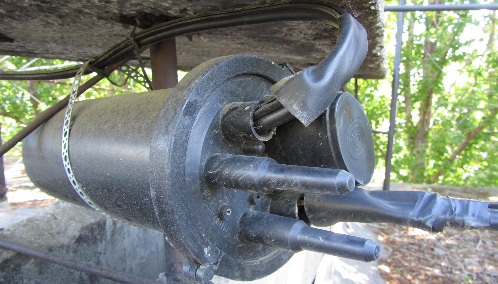
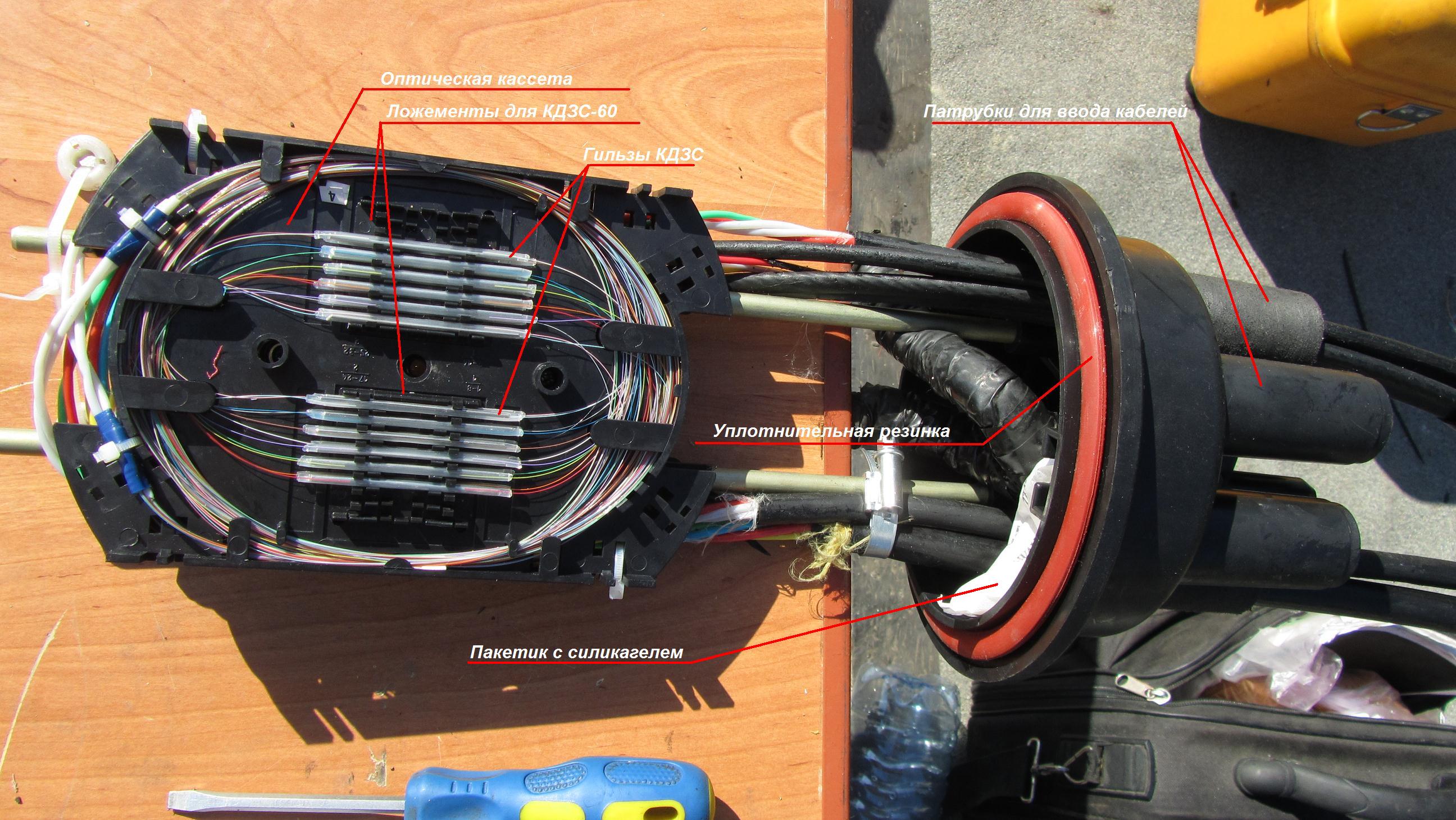
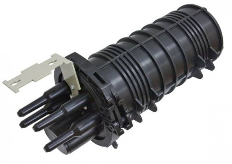
An optical coupling is a plastic container into which cables are inserted and connected there. Earlier, in the late 90s and early 2000s, when all specialized materials for optics were deficient with sky-high prices, some nimble guys made sewer fittings or plastic bottles as couplings. Sometimes even worked for several years. :) Today, of course, this is wildness, normal couplings can be bought in any medium and large city, and prices start at 1500-2000 rubles. Much designs of couplings. The most massive and familiar design for me personally is like in the MTOK series of construction and detal coupling couplings. There is a headband from which nozzles for cable entry protrude from the outside. A metal frame is attached to the inside of the headband, to which optical cassettes are attached.A cap is put on top (which can be made with stiffeners for durability), sealed with an elastic band. The cap is fixed with a detachable plastic clamp: the coupling can always be opened and closed without spending a repair kit of heat shrinkage.
In general, Svyazstroydetal makes generally good couplers for different applications. From the MTOK series, I personally like the L6 clutch most of all: universal, inexpensive, simply mounted.
There are also other couplings in the MTOK series - small-sized, for sewerage, for input of armored cables, for burying underground. For each coupling there is an opportunity to purchase additional components and sets for cable entry: for example, cast-iron body armor of an underground MZhZ coupling, an extra set of optical cassettes with consumables or an additional set for the input of another cable.
If you need cheaper - they have a series of MOG couplings, of which the most massive is the MOG-U coupling (Optical City Coupling, Shortened): at a price of less than 2000 rubles, we get a simple and high-quality coupling, which, however, some consider uncomfortable for installation.

On the pole, such a coupling will not look very good, and unwinding a cable with such a coupling while standing on the stairs is inconvenient, so they are usually placed in hatches. This coupling is designed to be placed in a telephone hatch on special standard consoles. The minus of the mogushki is that it does not have a locking detachable yoke and you have to cut the heat shrinkage to open it, and when closing it is necessary to spend a repair kit of wide shrinking (if cables are wired from one end) or heat shrinkable cuff (if there are cables on both sides). The MTOKi series A also suffers. In addition, if cables are inserted from two sides, it is important not to forget to put a plastic pipe on one of the “sides” of cables beforehand, otherwise it can’t be put on without cutting it: newcomers suffer as well.
Also sometimes there are couplings without nozzles, in which the cables are sealed by clamping in wet rubber or in sealant. Here, for example, the “SNR-A” coupling, which my partner and I cooked during the construction of the FTTB ring.
This method of sealing cables requires great care, because otherwise water can get into the coupling, which is undesirable. First, the water in the clutch over time can cause a cloud of glass fibers and damage the paint. Secondly, any metal constructive elements will rust, the wire earthing armor, if any, will rot. Thirdly, Kevlar will pull water into itself. And most importantly - a clutch full of water, in the cold just crush along with the fibers.
At least two cables are usually routed to the optical coupling. Of course, it is possible to come up with a wild pattern of unwelding, when one cable is inserted and boiled over by itself, but usually 2-3 cables are inserted. If 4-5 cables are inserted, and even all the cables are different with different colors and different amounts of fibers in the modules, the coupling is difficult to install and then parse to where it is soldered. I cooked my first such clutch with a partner for 3 days! :) So it is better to design the network so that the coupling does not include more than 3 cables.
Optical Crosses
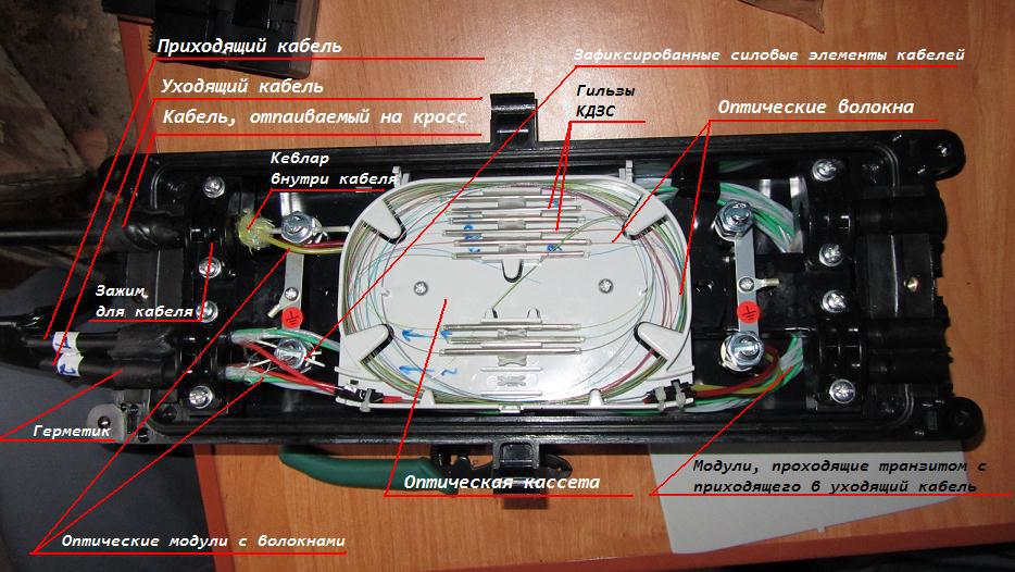
Optical cross is designed to terminate the cable in the place where it was connected: at the base station, in the ITC, in the data center, in the server room. A typical cross is a metal box of standard size 19 "for mounting in a standard rack, an end cable is inserted into the back of it, and there are slats with ports in the front.
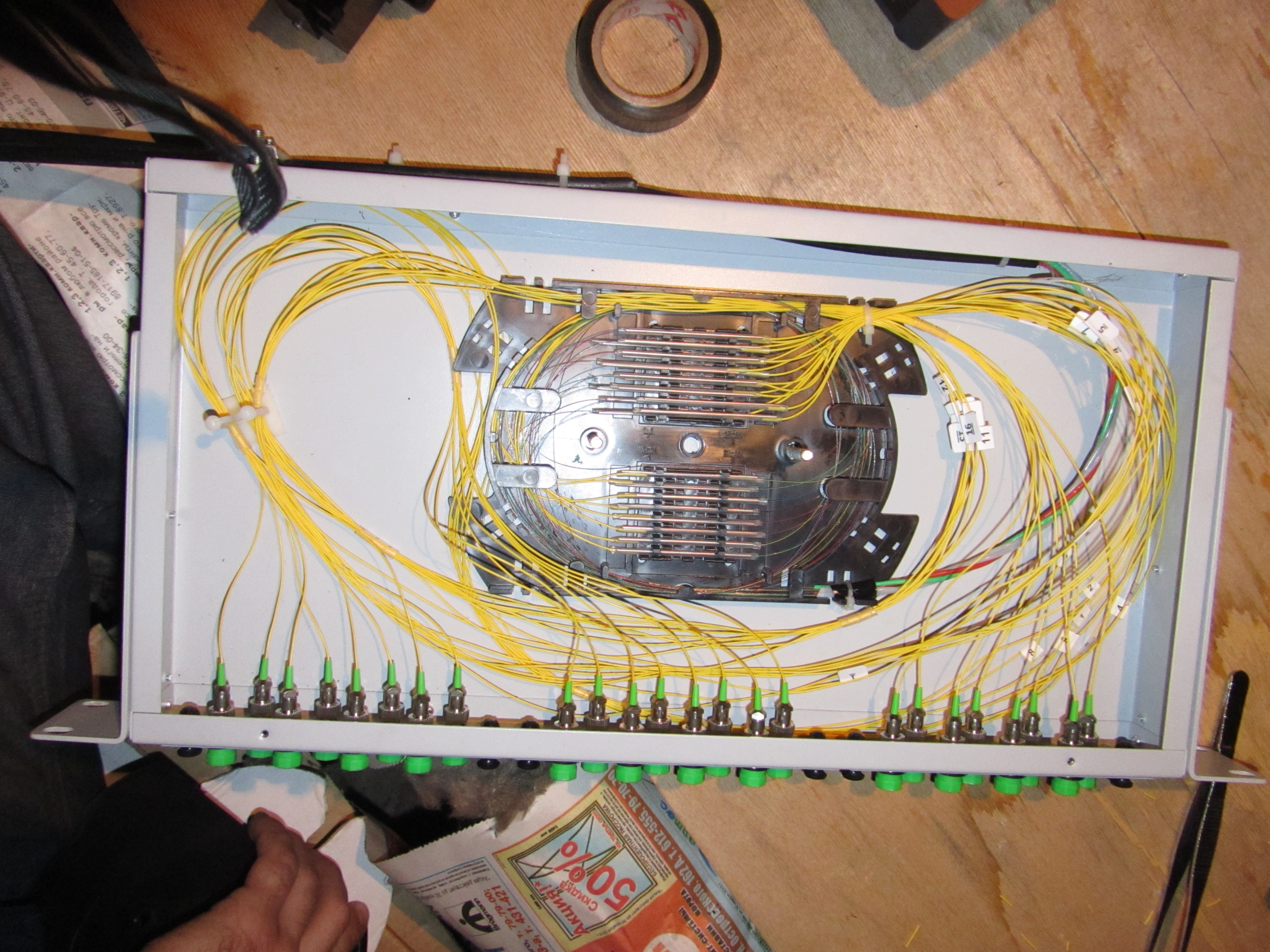
24 / FC / APC single port single cross welded
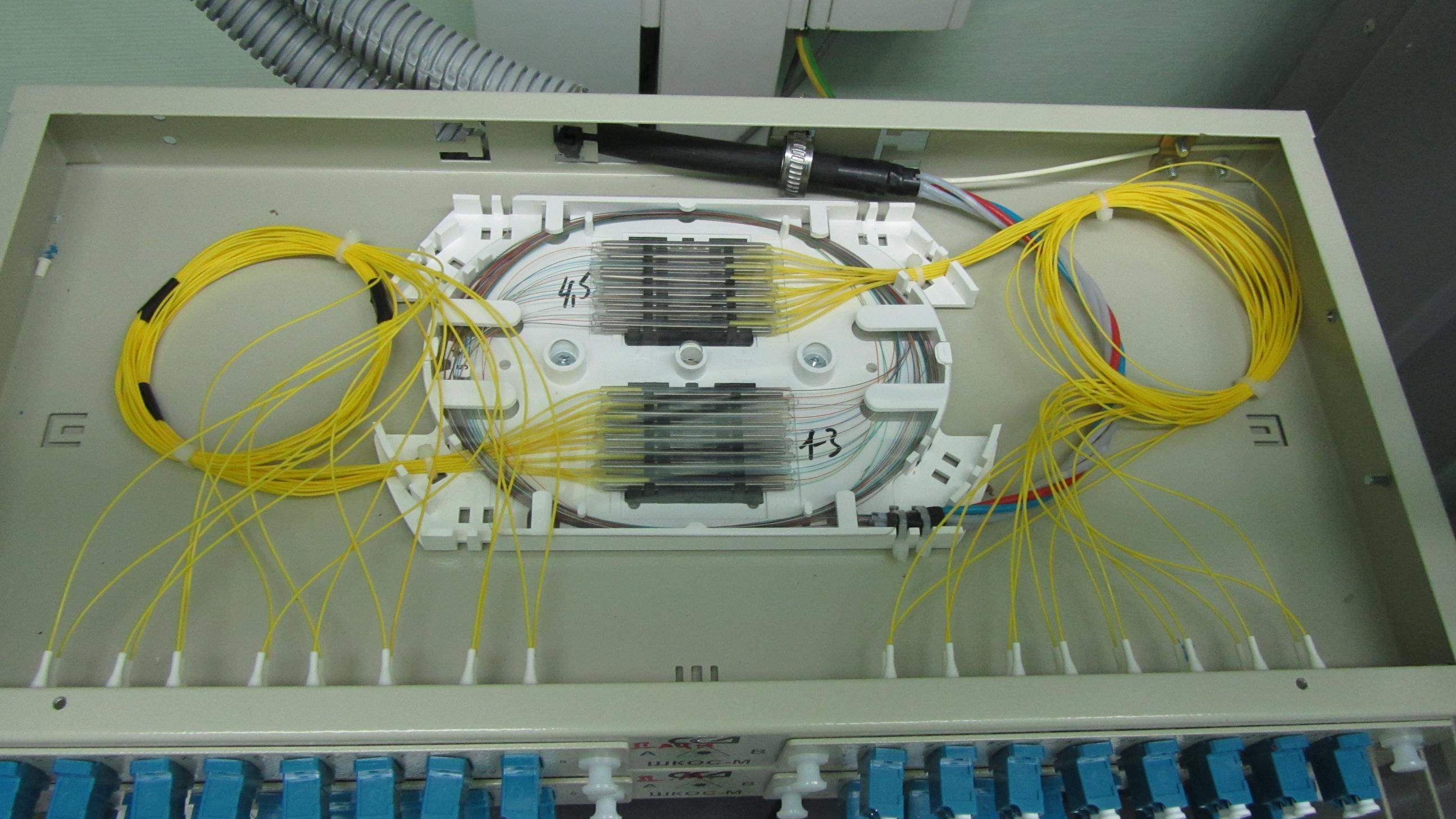
Welded cross to 64 ports of type LC, 2-hunitovy
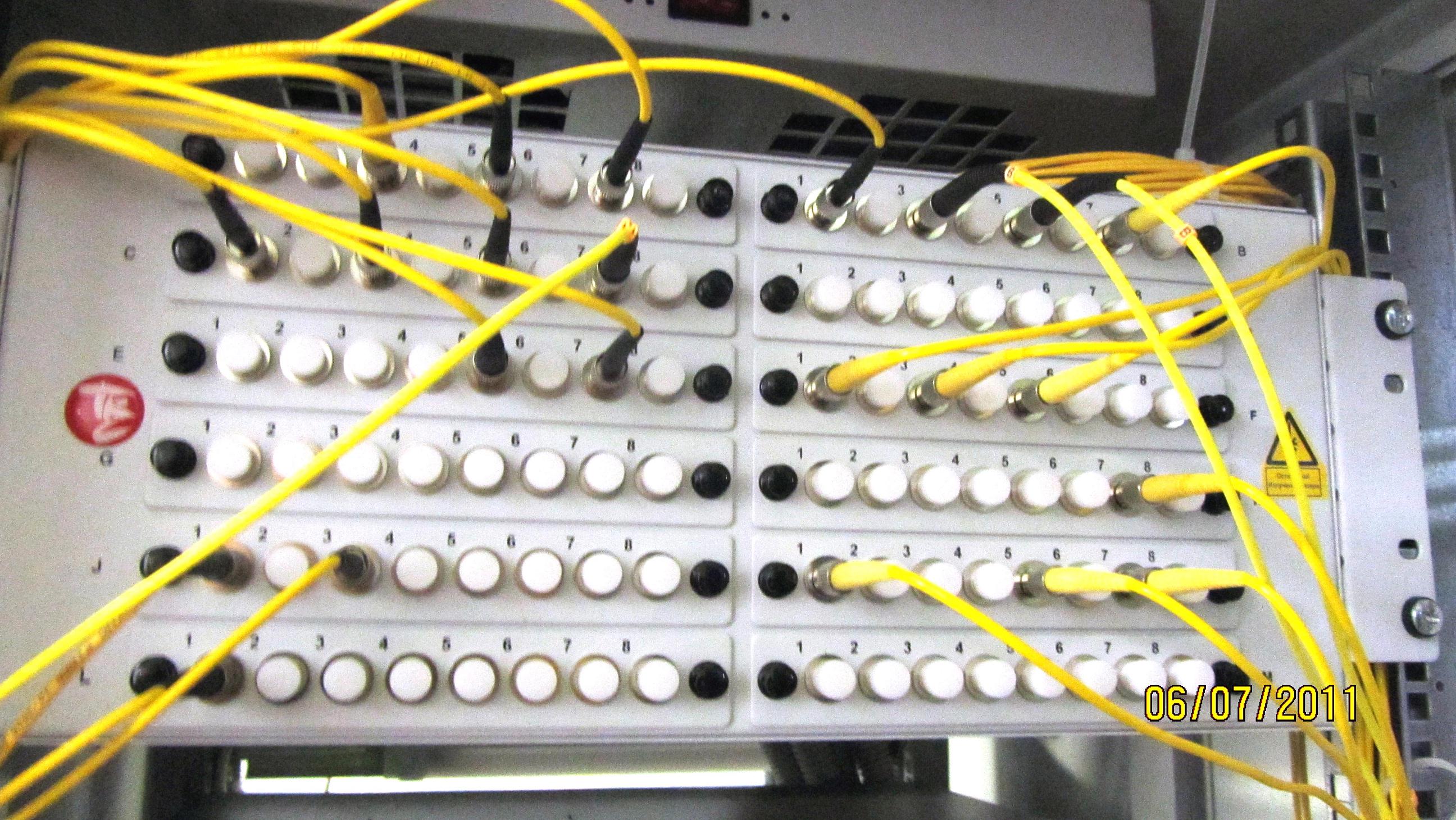
96-port working cross type FC
It happens and the option is cheaper - when from the cross throw everything that is possible, then it turns out somehow like this:

Open cross to 8 ports of type SC / APC, 1 unit. The bad news is that the optical pigtails are not protected by anything and can be broken by those who dig in a box / rack, dragging, say, a new cable.
All of these crosses are mounted in a rack, however, there are wall options, and other rare.
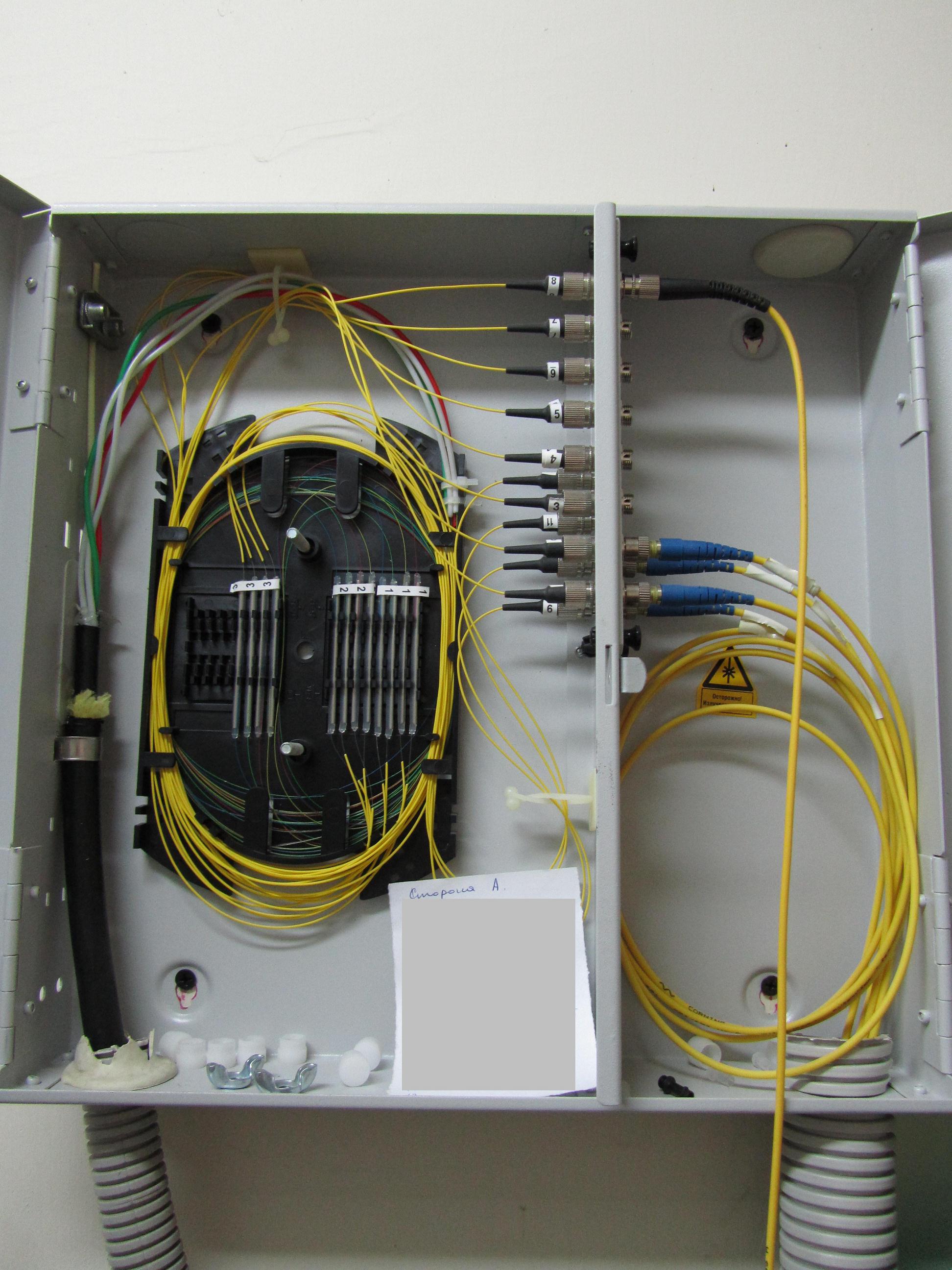
Wall cross on 16 ports of type FC. By the way, it is welded poorly: the yellow shells of pig-tails do not enter KDZS and the fibers may break, and the fibers in the cassette are laid with small bending radii
The cable introduced into the cross section is welded to the so-called pigtails: in the photographs they are thin yellow laces inside the crosses. Each fiber - to its pigtail. The other side of the pig-tail contains an optical “plug” connector, which is inserted into an optical “socket” adapter from inside the cross. Outside of the cross, switching is performed by optical patch cords (thick yellow cords). The patch cord differs from the pig-tail with a stronger connector and the presence of Kevlar inside, so that in the event that someone hooks on the patch cord and pulls, it is difficult to tear it out. Well, connectors for patch cords on both sides, and for pig-tails with only one. If necessary, a temporary patch cord can be welded from two pig-tails.
In principle, several cables can be made in the cross, some of the fibers can be welded together, and part of them can be brought to the ports. Then we get something that can be called "cross-coupling", while we save on materials and welds. This is sometimes done when installing FTTB, however, it is undesirable to do so, as the complexity of the circuit increases.
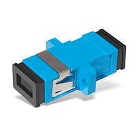
Adapters and connectors
Optical crosses are characterized by adapters used in them (easier - optical sockets). There are also a large number of standards and substandards.
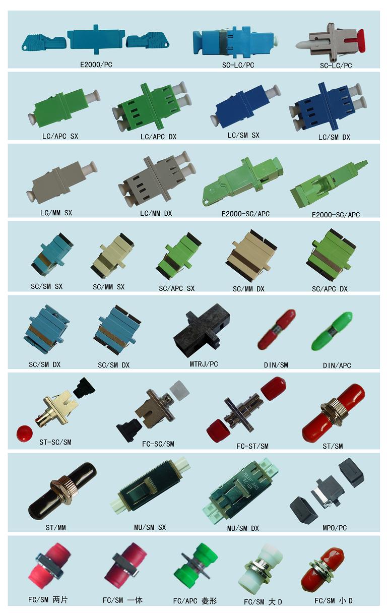
In this picture - only part of the “genera” and “types” of optical outlets
The standard is a complex of adapter (socket) and connector (plug). Of course, there are adapters between different standards, however these are crutches that will fit only for measurements and which should be avoided in a constantly working communication line. The fewer in the line of all kinds of welded and especially mechanical joints, the better. Of course, if the distance is small, the line will work, even if a decibel pair is lost at some of the crosses. In the case of short lines, optical attenuators are sometimes specially placed. But for very long lines, where the equipment operates at the limit, adding another cross or coupling (that is, some 0.05-0.1 dB loss) can be fatal: the line will not rise.
The tip of the "fork" is, roughly speaking, a cylinder with a thin through-hole under the fiber in the center. The end of this cylinder is not flat, but slightly convex. The tip consists of awesomely hard and scratch-resistant metal ceramics, although metal is very rare. It is rumored that people broke the side cutters, trying to figure out this tip. :) I myself easily scratched steel and glass with these tips. Nevertheless, they should be handled with care, to prevent dust from entering, not to touch the end of the connectors with your finger, and if touched - wipe with a napkin moistened with alcohol. Ideally, a special microscope (optical or camera) is used to monitor the condition of the patch cords. Dirty - cleaned, scratched, if the scratch crosses the center with glued fiber - under the writing off or polishing. Dirty and scratched sockets and patch cords are a common cause of line attenuation.
Optical fiber is fixed in the tip by gluing with epoxy (or some other) glue and subsequent grinding on a special machine, although this is done only if you need to make long non-standard patch cords: it is easier and cheaper to buy ready-made ones. The price of a conventional optical patch cord 2 meters long is about 200-400 rubles.
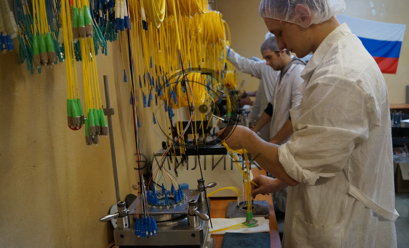
Making patch cords. Emilink
In practice, standards such as FC, SC, LC are most commonly used. Less common are FC / APC, SC / APC, ST. LC can be either duplex or single.
FC
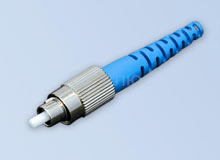
Pros - excellent quality connections, therefore, suitable for responsible highways. Old proven standard. Metal (hard to break). If you move your hand a well-screwed connector, it will not affect the connection.
Cons - long unscrew / twist when switching. If the cross-country is located closely - it is very inconvenient to crawl to unscrew some of the connectors in the crowd of others.
The connector itself is fixed motionless due to a groove on it and a notch on the adapter, and only a nut with a notch turns with your fingers.
The contact side of the tip is not flat, but slightly convex (this also applies to other standards), so that the two fibers from the two tips on opposite sides of the outlet (pigtail and patch cord) are guaranteed to be combined without air and dust between them.
The socket contains a hollow thin-walled ceramic cylinder with a longitudinal section. When the plug is inserted into the socket, the incision is distributed to some microns, springing and centering the plug. Thus, precise alignment of the two connectors in the outlet is achieved (remember that the signal is transmitted through the core of a fiber with a diameter of 9 μm and a shift even by 1 μm causes a loss of signal power at the outlet and a parasitic back reflection). Therefore, dust and dirt are harmful for optical sneakers, patch cords and pigtails should be regularly cleaned with a lint-free cloth with alcohol, and the sockets should be blown out with compressed air or cleaned with special cleaning sticks. A common cause of communication failure is a broken ceramic insert in the socket.
To connect the connectors tightly to each other, each FC and FC / APC connector (whether it is a patch cord or pigtail connector) has a metal-ceramic tip that is spring-loaded and can “press” into the plug about a millimeter and a half. In the SC, LC, ST standards, the entire plug is spring-loaded, and in the case of ST, the locking element is very similar to that used in local networks on a thin coaxial.
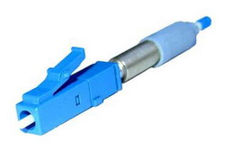
SC

All the same as in FC, only the adapter and the connector are square, plastic and the connector is fixed by snapping, not screwing. Pros are cheaper than FC, it is more convenient and faster to switch, cons - plastic is easier to break, less connection-disconnection resource. Sometimes it happens that the magnitude of reflection and attenuation at the connection changes noticeably after touching the connected connector, which is undesirable for responsible lines. The color of the connectors is usually blue.
LC and LC Duplex
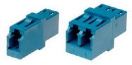
The properties are similar to SC, but they have much smaller dimensions: a dual-unit cross on an LC can hold as many as 64 ports, and on a SC - only 32. Due to their small dimensions, they are often mounted directly on optical multiplexer boards.
FC / APC, SC / APC, LC / APC
Same as FC, SC and LC, but with a scythe (A - angle, angle) by polishing the tip.
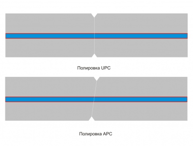
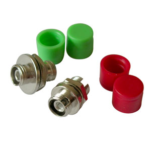
The difference between ceramic tips with regular and oblique polishing. The image is a bit inaccurate: in fact, in the case of both polishing and the other polishing, the ends are not flat, but slightly convex, respectively, when connecting, only the tip centers, where the fiber is in contact.
Such adapters and connectors are made in green and when compared with the usual polishing of UPC (or just PC), the difference is visible. This is necessary to reduce the back reflection at the junction of the two connectors. As far as I know, this type of polishing was developed for the transmission of analog television on optics in order to avoid ghosting of the image on the screen, but I can be mistaken.
It is possible to dock “ordinary” and “slanting” polishing between themselves, but only if it is necessary to take a reflectogram according to the principle “if only the length of the path is visible”: a large air gap will give strong losses and a strong back reflection.
Today my story is over. Ask questions, try to answer. If you find this topic interesting, I will write a sequel.
Source: https://habr.com/ru/post/193146/
All Articles