Method of measuring the effective value of voltage using MK
In this post we will discuss one of the options for measuring the effective value of voltage and frequency of the network on an 8-bit PIC18 microcontroller. If desired, the method can be transferred to any other MK, up to all your favorite ARDUINO (if they support the implementation of timer interrupts with a frequency of 5-10 kHz).
Also, the considered method allows to measure the frequency of the mains voltage without the use of external additional means, such as comparators. But, at the same time, one has to sacrifice either the time resources of the MC or the accuracy of the frequency measurement.
Why is it important to measure the actual value, and not any other, for example, mean straight? Most of the “Chinese” electronic voltmeters measure the mains voltage according to the rectified average value. The measurement technique is as follows: for the period of the mains voltage, a sample of N amplitude values of the voltage is made, the results are added (without a sign), divided by N (averaged), after which the result is multiplied by a factor

The indicated coefficient determines the dependence of the effective value of the sinusoidal (!) Signal on the average rectified one.
This method of measurement is simple, does not require a lot of microcontroller resources (both temporary and memory resources). The main disadvantage of this measurement technique is a large measurement error on non-sinusoidal signals.
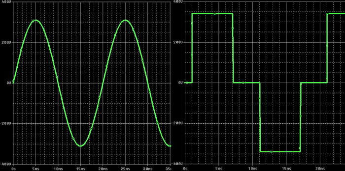
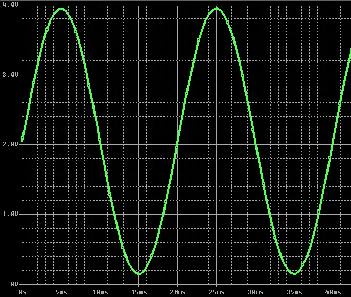
As everyone knows, the change in the mains voltage signal is subject to a sinusoidal law (due to the use of synchronous generators at a power plant), with a frequency of signal change of 50 Hz (60 Hz). However, in practice, due to the influence of third-party factors (mainly connecting to the network of powerful non-linear loads), as well as the use of inverters with quasi-sinusoidal output voltage (see figure), the sinusoid voltage is either significantly distorted or replaced by rectangular pulses. In such cases, the above measurement method will give a very large error (for example, in quasi-sinusoidal inverters, the output voltage measured by a “Chinese” voltmeter may be 180–200V, while the actual voltage will be 220V).
For example, stress at my home
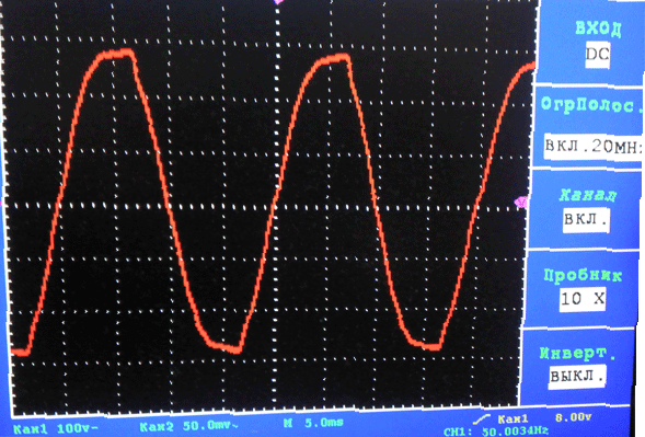
Why is it important to measure the actual value of the voltage (current)? Because it is the effective (also called effective) values of voltage and current that determine the operation of the electrical system (roughly speaking, the electric heater generates heat in direct proportion to the effective values of voltage and network current).
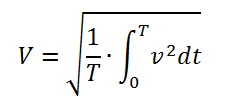
The effective value of the measured periodic value is calculated by the formula
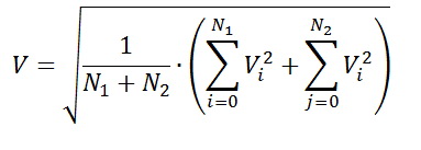
Or after sampling we get
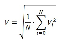
Those. we need to sample a series of values for the period of the mains voltage, sum up the values of the squares of the sampling points, divide by the number of points per period (when determining the number of sampling points, do not forget about the Kotelnikov-Shannon theorem), and take the square root of the result.
It seems to be nothing complicated, if not for but:
1) Each period, the sample points are recruited again, which increases the measurement error;
2) In a real network, near zero voltage, both “zero shelves” and repeated zero-voltage transitions can occur, which will significantly introduce an error in the measurement.
We will struggle with the first item by measuring the sum of the squares of the sample points for each half-period, after which we will sum the n-th sum of squares with (n + 1) -th and throw away the (n-1) -th.
We will struggle with the second item by introducing voltage-insensitive zones (we will enter the limits of the zero-crossing voltage from the positive and negative sides), usually 5-10 V in both directions, as well as dead-frequency zones in frequency (we will limit the allowed frequency of the voltage signal).
Thus, we obtain the calculated value of the effective value of the mains voltage for the period at each half period of the mains voltage.
The voltage frequency is calculated by the formula:

where Fd is the sampling frequency (for convenience and to increase the accuracy of frequency measurement, it is chosen equal to 10 kHz (sampling period is 100 μs)).
Now we will consider the block diagram of the measuring part (in the real scheme we should add filtering and protective elements).
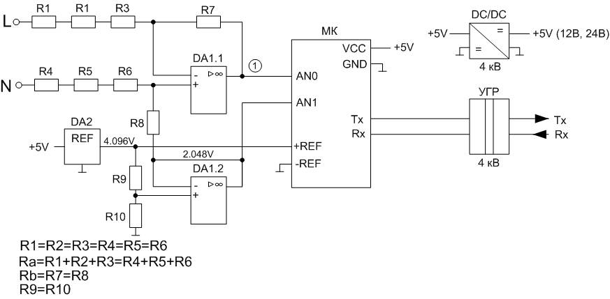
Attention! In this method of measurement, the galvanic isolation of the microcontroller from the network is not implemented. The galvanic connection is implemented on the side of the digital data interface from the microcontroller.
A differential operational amplifier with a voltage divider supported by half of the reference voltage (2.048 V) is installed at the input. Since, to reduce the size it is better to use low-power resistors, we install them at least 3 pieces. equal in resistance - to increase the total breakdown voltage of resistors. In this case, it is necessary to calculate the power loss at the maximum input voltage (P = U ^ 2 / R) - so that it does not exceed the permissible power of the resistors. The shoulders of the differential amplifier are also equal. Then, the voltage at point 1 is calculated by the formula:
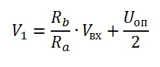
And the voltage at point 1 will be:
Also, half of the reference voltage is applied to one of the ADC channels. This allows continuous positioning (for example, once per period) to determine the position of the zero level of the measured voltage.
Those. we managed with an unipolar powering op amp, and our input signal at point 1 varies from 0 to Uop. This method gives fairly accurate results, compared, for example, with the rectification voltage using diodes.
The calculation of the divider and the ADC coefficient is as follows:

where A and B are the ADC measurements (minus the measured value of the signal zero - AN1) for the current and previous half periods; N1, N2 - the number of measurements for the current and previous half periods; Nad - ADC digit capacity; U'op is the reference voltage minus the non-linearity (insensitivity) zones of the operational amplifier (usually 0.6 V).
Calculation of the divider is conveniently carried out considering the signal to be constant, reduced to the amplitude of a sinusoidal, and not sinusoidal. Then the effective value of the signal is equal to the amplitude and equal to the value of each measurement.
For example, you need to calculate the divider to measure the maximum value of 420V AC:

The resistance Ra is selected in the range from 500 kΩ to 1500 kΩ. For the selected resistance Ra, Rb is calculated.
As a result, the algorithm for calculating the effective value of voltage and frequency takes the form:
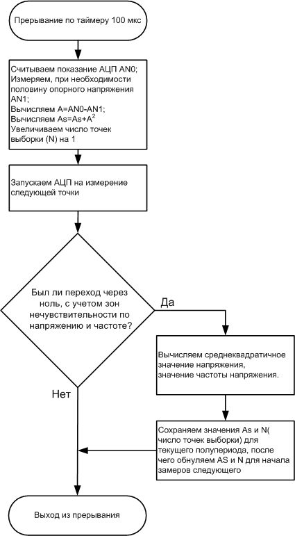
In this case, part of the cost calculations (division, extraction of the root) can be transferred from the interruption to the main program.
')
When calculating effective values on an 8-bit MC, it is advisable to use integer methods (using scale factors) without resorting to floating-point calculations, and also to simplify as far as possible arithmetic operations (division, removal of a square root, etc.). This greatly saves resources MK.
Also, the considered method allows to measure the frequency of the mains voltage without the use of external additional means, such as comparators. But, at the same time, one has to sacrifice either the time resources of the MC or the accuracy of the frequency measurement.
Why is it important to measure the actual value, and not any other, for example, mean straight? Most of the “Chinese” electronic voltmeters measure the mains voltage according to the rectified average value. The measurement technique is as follows: for the period of the mains voltage, a sample of N amplitude values of the voltage is made, the results are added (without a sign), divided by N (averaged), after which the result is multiplied by a factor
The indicated coefficient determines the dependence of the effective value of the sinusoidal (!) Signal on the average rectified one.
This method of measurement is simple, does not require a lot of microcontroller resources (both temporary and memory resources). The main disadvantage of this measurement technique is a large measurement error on non-sinusoidal signals.
As everyone knows, the change in the mains voltage signal is subject to a sinusoidal law (due to the use of synchronous generators at a power plant), with a frequency of signal change of 50 Hz (60 Hz). However, in practice, due to the influence of third-party factors (mainly connecting to the network of powerful non-linear loads), as well as the use of inverters with quasi-sinusoidal output voltage (see figure), the sinusoid voltage is either significantly distorted or replaced by rectangular pulses. In such cases, the above measurement method will give a very large error (for example, in quasi-sinusoidal inverters, the output voltage measured by a “Chinese” voltmeter may be 180–200V, while the actual voltage will be 220V).
For example, stress at my home
Why is it important to measure the actual value of the voltage (current)? Because it is the effective (also called effective) values of voltage and current that determine the operation of the electrical system (roughly speaking, the electric heater generates heat in direct proportion to the effective values of voltage and network current).
The effective value of the measured periodic value is calculated by the formula
Or after sampling we get
Those. we need to sample a series of values for the period of the mains voltage, sum up the values of the squares of the sampling points, divide by the number of points per period (when determining the number of sampling points, do not forget about the Kotelnikov-Shannon theorem), and take the square root of the result.
It seems to be nothing complicated, if not for but:
1) Each period, the sample points are recruited again, which increases the measurement error;
2) In a real network, near zero voltage, both “zero shelves” and repeated zero-voltage transitions can occur, which will significantly introduce an error in the measurement.
We will struggle with the first item by measuring the sum of the squares of the sample points for each half-period, after which we will sum the n-th sum of squares with (n + 1) -th and throw away the (n-1) -th.
We will struggle with the second item by introducing voltage-insensitive zones (we will enter the limits of the zero-crossing voltage from the positive and negative sides), usually 5-10 V in both directions, as well as dead-frequency zones in frequency (we will limit the allowed frequency of the voltage signal).
Thus, we obtain the calculated value of the effective value of the mains voltage for the period at each half period of the mains voltage.
The voltage frequency is calculated by the formula:
where Fd is the sampling frequency (for convenience and to increase the accuracy of frequency measurement, it is chosen equal to 10 kHz (sampling period is 100 μs)).
Now we will consider the block diagram of the measuring part (in the real scheme we should add filtering and protective elements).
Attention! In this method of measurement, the galvanic isolation of the microcontroller from the network is not implemented. The galvanic connection is implemented on the side of the digital data interface from the microcontroller.
A differential operational amplifier with a voltage divider supported by half of the reference voltage (2.048 V) is installed at the input. Since, to reduce the size it is better to use low-power resistors, we install them at least 3 pieces. equal in resistance - to increase the total breakdown voltage of resistors. In this case, it is necessary to calculate the power loss at the maximum input voltage (P = U ^ 2 / R) - so that it does not exceed the permissible power of the resistors. The shoulders of the differential amplifier are also equal. Then, the voltage at point 1 is calculated by the formula:
And the voltage at point 1 will be:
Also, half of the reference voltage is applied to one of the ADC channels. This allows continuous positioning (for example, once per period) to determine the position of the zero level of the measured voltage.
Those. we managed with an unipolar powering op amp, and our input signal at point 1 varies from 0 to Uop. This method gives fairly accurate results, compared, for example, with the rectification voltage using diodes.
The calculation of the divider and the ADC coefficient is as follows:
where A and B are the ADC measurements (minus the measured value of the signal zero - AN1) for the current and previous half periods; N1, N2 - the number of measurements for the current and previous half periods; Nad - ADC digit capacity; U'op is the reference voltage minus the non-linearity (insensitivity) zones of the operational amplifier (usually 0.6 V).
Calculation of the divider is conveniently carried out considering the signal to be constant, reduced to the amplitude of a sinusoidal, and not sinusoidal. Then the effective value of the signal is equal to the amplitude and equal to the value of each measurement.
For example, you need to calculate the divider to measure the maximum value of 420V AC:
The resistance Ra is selected in the range from 500 kΩ to 1500 kΩ. For the selected resistance Ra, Rb is calculated.
As a result, the algorithm for calculating the effective value of voltage and frequency takes the form:
In this case, part of the cost calculations (division, extraction of the root) can be transferred from the interruption to the main program.
')
When calculating effective values on an 8-bit MC, it is advisable to use integer methods (using scale factors) without resorting to floating-point calculations, and also to simplify as far as possible arithmetic operations (division, removal of a square root, etc.). This greatly saves resources MK.
Source: https://habr.com/ru/post/193022/
All Articles