Automatic blinds on Arduino

The idea of blinds automation originated in my head a long time ago. The specific arrangement of the windows of my room contributed particularly to this: after dinner, bright sunlight beats into my windows, interfering with computer work and discouraging every desire to engage in productive activities. At the same time, being in a room with closed shutters is a pleasure, in my opinion, dubious. I wanted to get a system that allows to automatically change the angle of rotation of the valves, depending on the intensity of sunlight, as well as having the ability to manually control from a remote control.
The first task was to automate the valves themselves. An engine is needed for turning and a sensor that will indicate the position in which the louver flaps themselves are located.

The main obstacle to installing the engine was a regular worm drive changing the angle of rotation of the valves. Its presence blocked the possibility of internal installation of the motor, while placing the engine outside, in the place of the standard handle, was also very difficult. Ultimately, it was decided to completely dismantle the manual mechanism and install the motor in the inner part of the blinds.
')
The engine used was a GM12-N20VA Micro Geared Motor gearbox:

This engine has the following characteristics:
- Operating voltage: 2 - 5 V
- Rated voltage: 5 V
- Gear ratio: 100: 1
- No load speed: 145 rpm
- No load current: 40 mA
- Speed under load: 100 rpm
- Load current: not less than 150 mA
- Torque under load: 0.2 kg / cm
- Current when locked: 520 mA
- Torque: 0.78 kg / cm
- Size (L x W x H): 24 x 12 x 10 mm
- Output shaft: D-shaped, d = 3 mm, length 10 mm.
The output shaft of the motor itself turned out to be slightly smaller than the hole in the louvre mechanism, therefore, to ensure a tight connection, heat shrinkage was soldered onto the shaft.

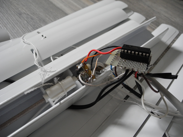
To control the motor, I used a fairly common, and well-proven chip for the dual-channel driver driver L293D.
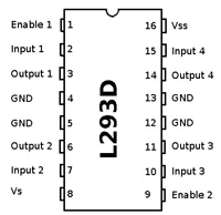
The motor is connected to the Output 1 and Output 2 of the microcircuit, depending on the signals on the feet of Input 1 and Input 2, the motor rotates in one or the other direction, similarly for the second channel.
Everything turned out to be not so simple with the position sensor as I assumed earlier. Of all the options for its design, I stopped at a potentiometer mounted on the same axis as the motor, which was subsequently connected to the controller's ADC.
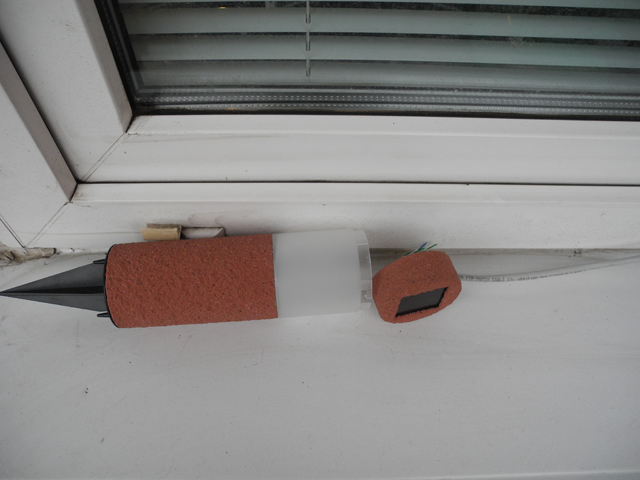
To my surprise with the light sensor problems turned out to be the least. I used a solar panel extracted from an inexpensive LED flashlight purchased at a hardware store. The cover of the flashlight itself served as a good body.
For remote control, I used a TSOP31236 IR receiver with a remote control from the Master KIT kit, but in this case, you can use any other.

The whole scheme is as follows:

Depending on the data received on the ADC from the light sensor, the louver flaps move to one or another position, while the current position of the flaps is monitored by a sensor, which is a potentiometer connected to the Adruino analog input.
To work with IR remote control, I did not reinvent the wheel and used the already prepared IRremote library.
Here is the actual video illustrating the work:
In the absence of sunny weather, the sensitivity of the sensor has been reduced.
In the future, I would like to transfer the system to a more “serious” microcontroller, place all the elements compactly, on one printed circuit board and hide it in the case.
Source: https://habr.com/ru/post/192648/
All Articles