Cellular Test Base Station: What's Inside
You know, after switching to optical fiber, we began to take out less hunting bullets from cables.
About this, as well as about what has changed since the transition to new technologies, I will describe below. Now we will go to the base station in our office. It is not quite normal: on the one hand, it is an operating base station, on the other - it is also used to test and test new equipment.
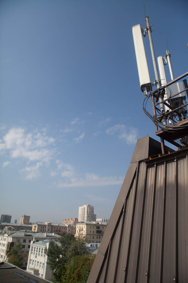
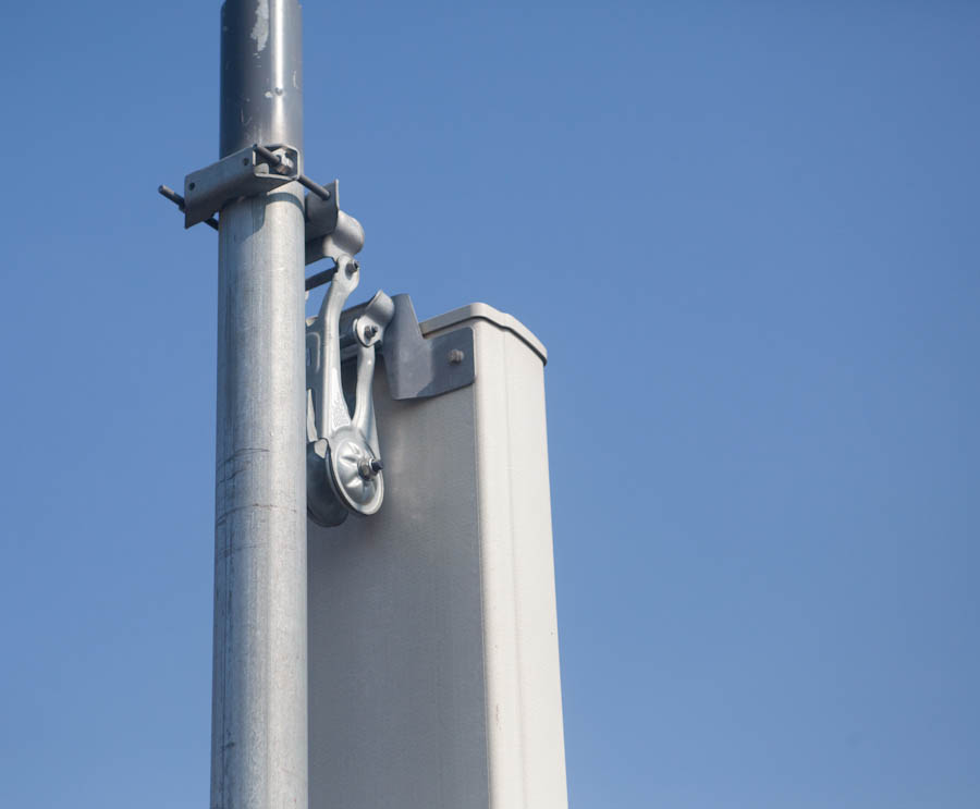
This is how BS antennas look like; their position can be controlled remotely.
')
Antenna Motor Controller (Top Rack Unit)
Be careful , there are a lot of photo traffic below.
Many believe that the antennas installed on the roof, and are the base station. This is not entirely accurate - they represent one of its elements, specifically, a device for receiving and transmitting a cellular signal from the subscriber to the subscriber, then to the base station itself, to the controller and other control devices.
Here is the signal path (very simplistic):
1) Your signal is received by antennas at one of the sectors of the base station;
2) Passes through the amplifier, where the level of the received and transmitted signal is equalized (from the weak transmitter of the telephone);
3) Enhanced remote controllable radio module;
4) Through the base station goes on to the controller, where the processing and switching takes place;
5) Data is processed and transmitted to voice and packet traffic switches, connecting subscribers to each other and to the Internet.
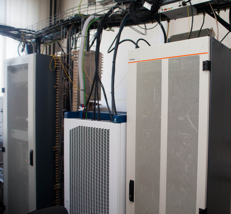
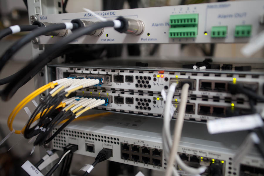
Below is a photo of the room with the equipment of base stations. Usually such rooms are much smaller than ours, and in containers for installation in open areas and even less space. In addition to the base station itself, there are many auxiliary equipment in the room, such as a cooling system, an alarm, a fire extinguishing system, and uninterruptible power supplies that the base station can operate for some time without external power supply.
On the right, a cellular network “dinosaur” is looking at us - a wardrobe with a 2G station. In the center - more modern equipment that supports the 3G standard.
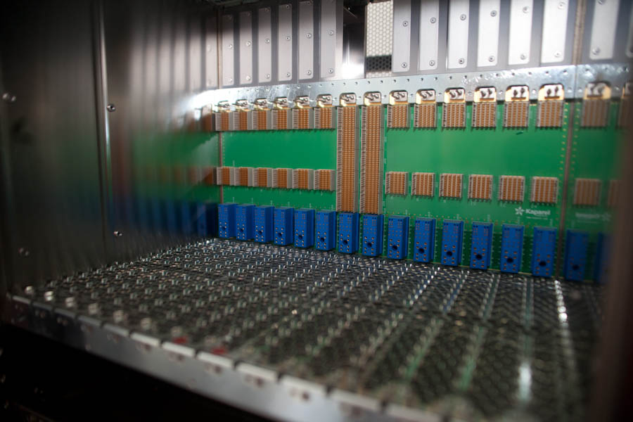
Here are the empty controller cells:
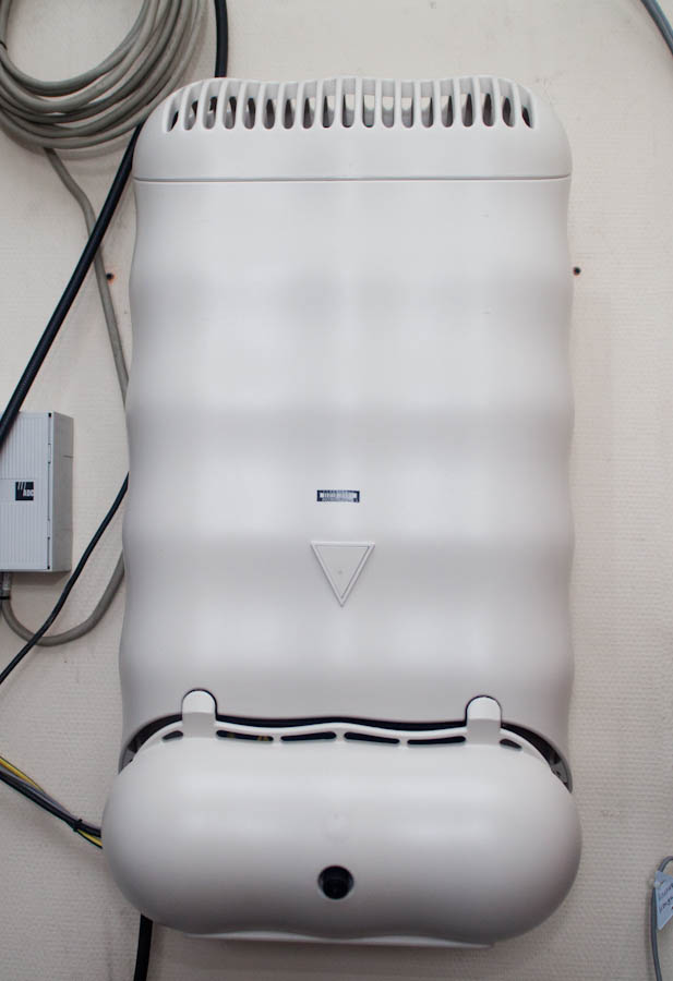
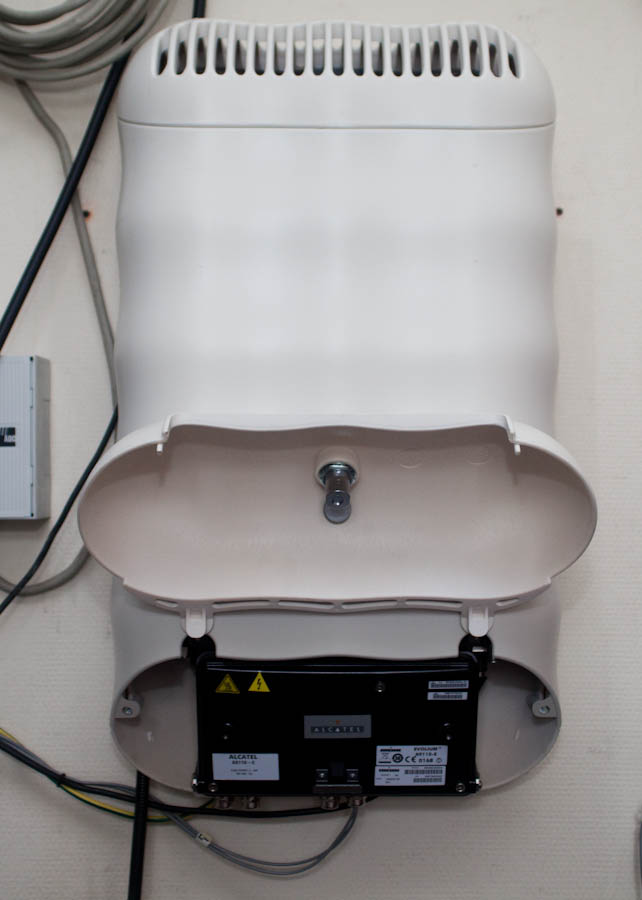
Another “exhibit” is fixed on the wall - one of the first base stations intended for organizing communication inside the premises, the so-called micro cells.
Another old device is a packet switching unit, DDF for two megabit streams.
This is where he inserted “elephants” connecting traffic flows. The device is really a bit like an elephant.
But let's look at the working equipment. This is what the old base stations look like from the inside:

On this equipment, the amplifiers are located in the base station itself, using signal transmission to the antennas over thick RF cables. More modern solutions use fiber and antenna units themselves.
Looking at this picture, you can understand what is the difference between the modern base station device (on the right) and what was.
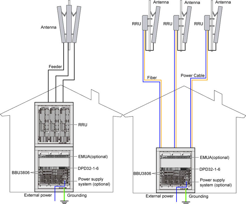
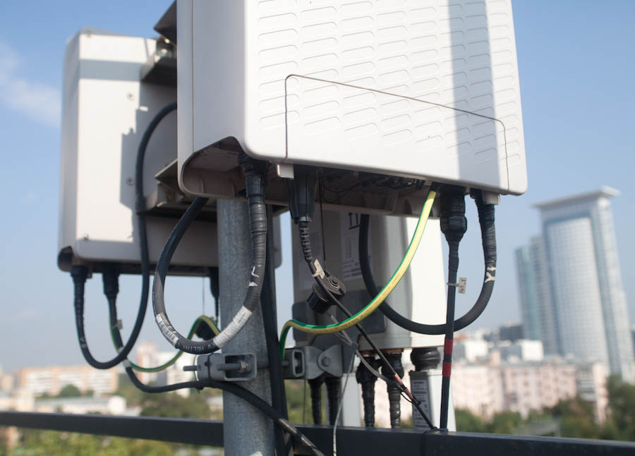
In the second case, the radio modules are installed next to the antennas:
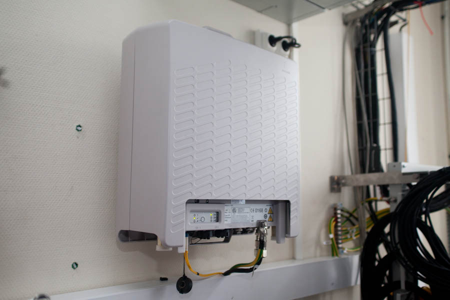
That's just the same radio module in the room. Here it is for the convenience of testing:
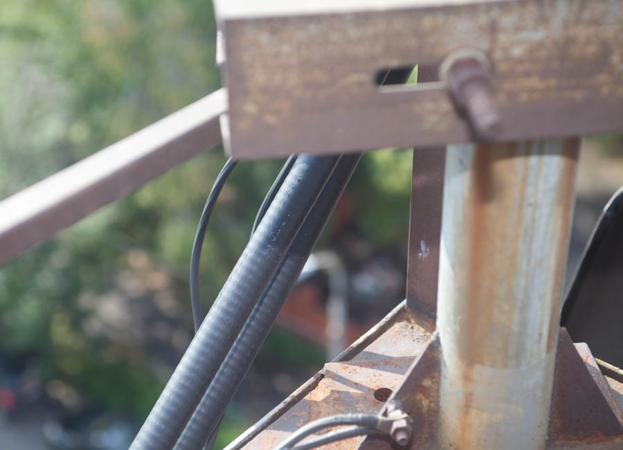
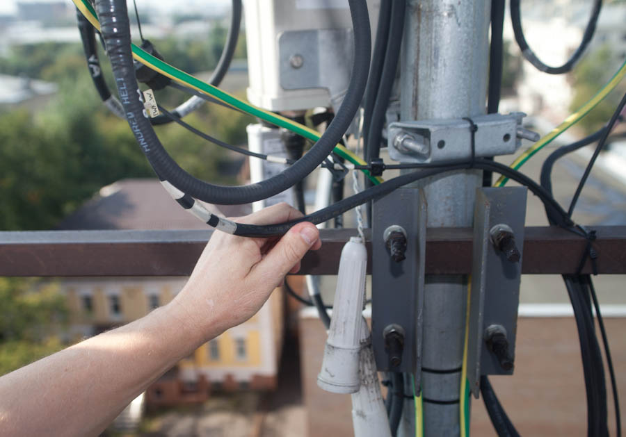
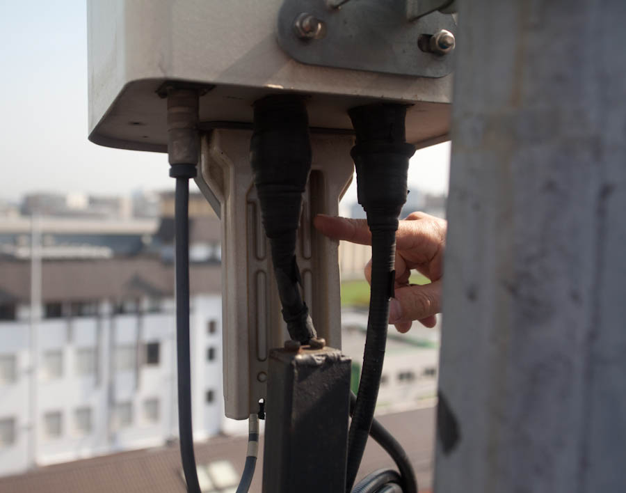
Previously, the feeder path was raised to the roof. It is about two of my fingers thick and practically does not bend with your hands. The connectors are large, often oxidized, get wet. Here he is:
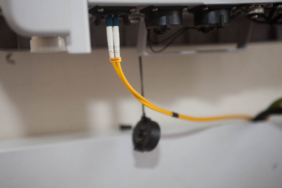
And this is a new connection, an optical fiber in an armored cable, it is very flexible and easy to install and maintain:
With the introduction of fiber, several other important benefits emerged: energy consumption decreased by several percent throughout the network (because the unit began to cool naturally outside), copper consumption for cables decreased, plus we began to go less often to remove bullets from the cable. Yes, it sounds ridiculous, but as soon as the hunting season begins, we begin regular failures due to a "shot feeder path". It's much more difficult to get into the optical fiber, because snipers are not yet mature enough, apparently.
And here is another conclusion without an armored braid, look how thin:
It is not always possible to use remote controlled modules (RRU) around the antennas themselves - in the southern regions of free cooling it may not be enough (but this is quite rare). In the north, winter helps a lot. For example, a photo of my colleague from Arkhangelsk, this is a block with an open lid.

Now let's go back to Moscow, go back to our room and look at the next cupboard. These are power supplies.

Below are the uninterruptible power supply (UPS) batteries, in which the base station is able to work for several hours if there are problems with electricity. If this problem occurs, we use the energy of a diesel generator.

Also, the base station can be powered from other sources, such as wind turbines or solar panels. During the restoration of communications after the floods in Krymsk, the generators were very helpful: the emergency team connected them to the station for several hours. During this time, the UPS batteries were charged to a sufficient level to give "rest" to the generator. The cycle was repeated until the city grid was restored.
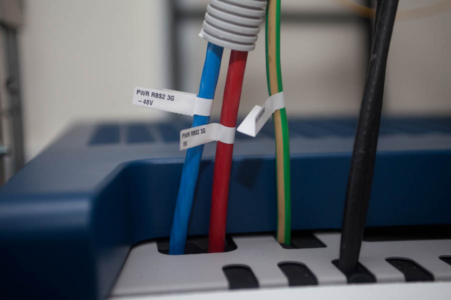
Base stations use 48 V.
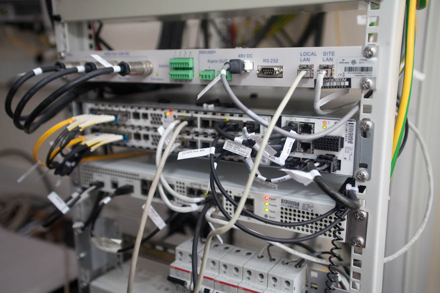
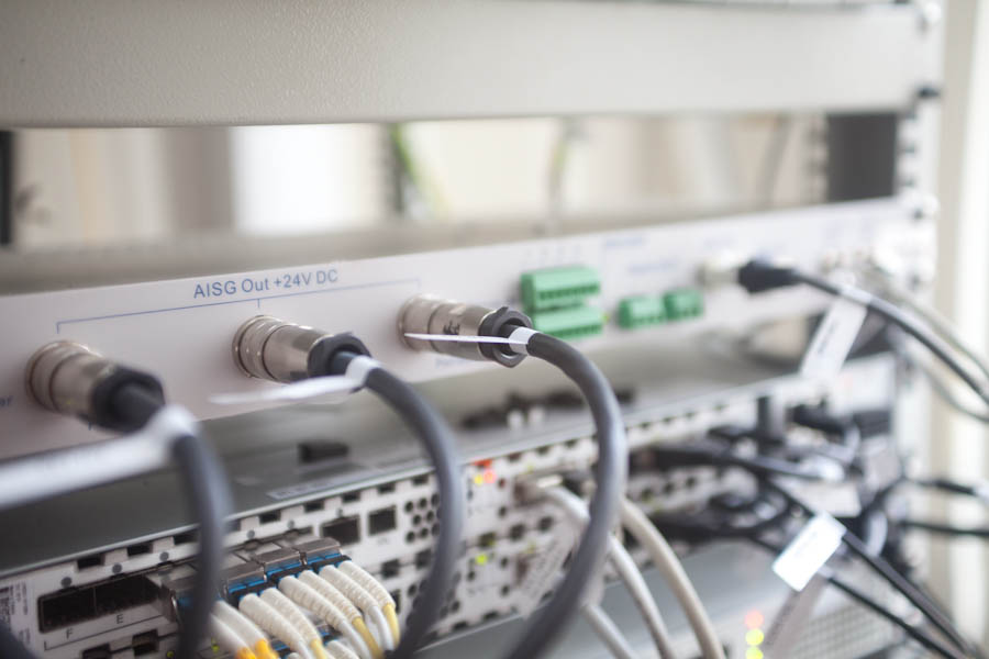
Opposite these cabinets there is a standard 19-inch rack in which several units are installed. So now looks like a modern base station, in this case, 3G and LTE. In addition, we know the antenna motor control unit, with which you can remotely change the electric tilt angle and transmit information to the control server.
The motor control device has been used for several years and has proven to be a reliable device that does not require much attention and time for maintenance.
You can connect to each motor at any base station remotely via a web interface or console and receive data on its status or give control commands. Previously, the antenna tilt angle could be changed only manually using the device shown in this photo.
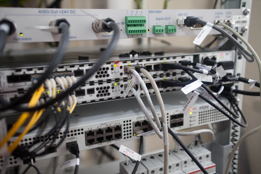
This is an LTE base station - its control part (second unit on top):
And this is the LNA control unit - a low-noise amplifier. The phone transmitter is weak, so the signal coming from it must be amplified, if possible, without distortion. This unit is just designed for this.

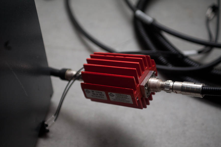
This is one of the devices that is used for testing equipment - the agreed load (a test device that allows you to check some parameters of a base station without putting it on the air):
Now up again! This is how the base station antennas usually look at the city.

In addition to antennas for transmitting a cellular signal, there is an antenna for transmitting information flows between base stations. This is a radio relay antenna. It is used where there is no possibility of transmitting information between base stations using optical links. There are several ways to transmit information channels. It can be transmitted in any way - from the optical cable and ending with a two-way satellite antenna with a satellite modem (like in our port in Dickson). This is a radio relay antenna:
Optical fiber comes from the BS below and looks like this:
Next, the fiber goes to remote radio-controlled units (transceivers) that are already familiar to you. This is, for example, a three-band antenna. Three antennas of 900, 1800 and 2100 bands are installed in its case. It differs from other antennas in its large size and weight (which makes its maintenance a little difficult). This antenna is equipped with a triple control motor.
Above the antenna you can see the pins. These are lightning rods:

Typically, repair of base stations and scheduled maintenance is done by contractors. But our department also constantly takes part in the repair and maintenance of base stations and antennas, so we also have our own equipment for measuring. In the photo - equipment. Below it are thick black cables - these are feeder jumpers. The feeder is heavy, it bends poorly, it is difficult to connect it. Therefore, such an elastic short adapter is used.
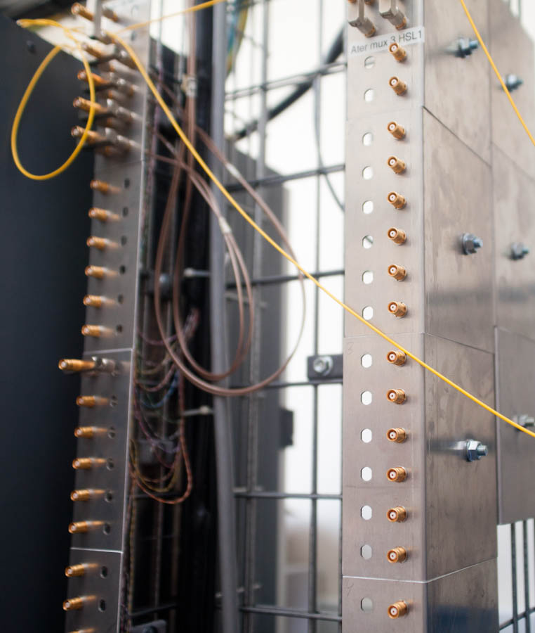
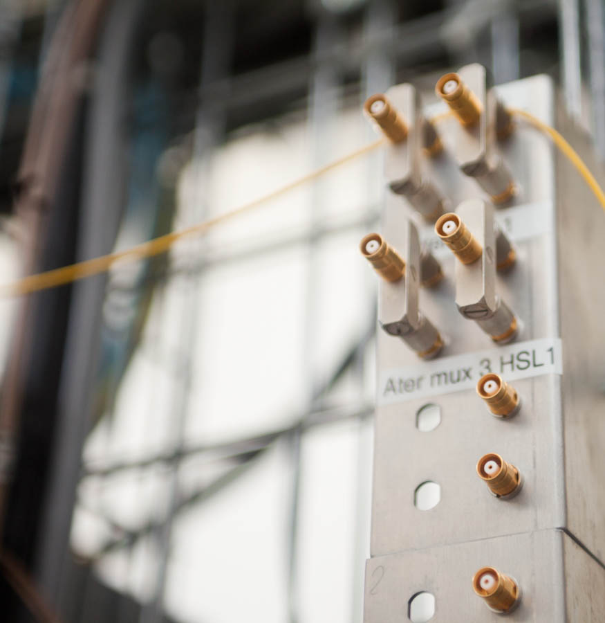
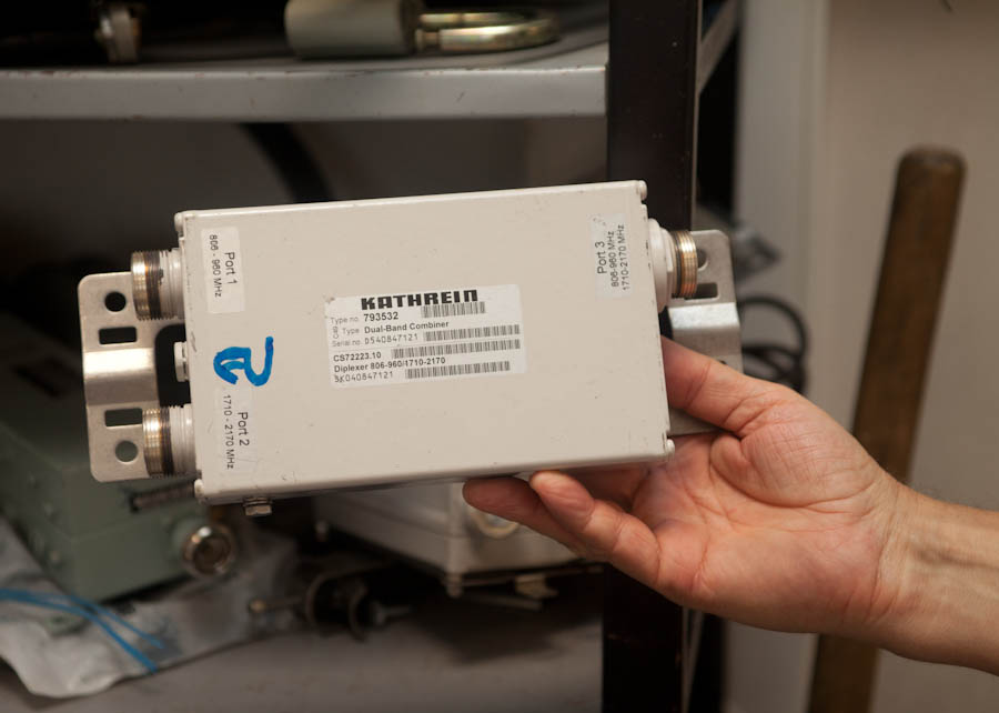
Sometimes it happens that one cable needs to transmit signals to the antenna in several bands, for example, 900 and 2170. Where the second cable cannot be laid for various reasons, a combiner is used. The principle of operation is a multiplexer and a demultiplexer. The quality of the line suffers somewhat, but you have to sacrifice something.
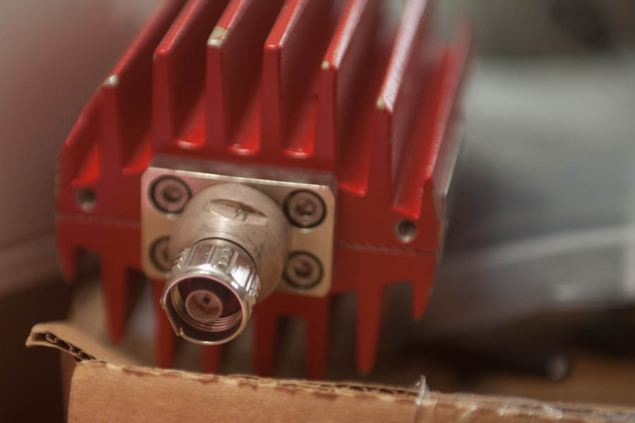
Here are the connectors installed on the feeders.

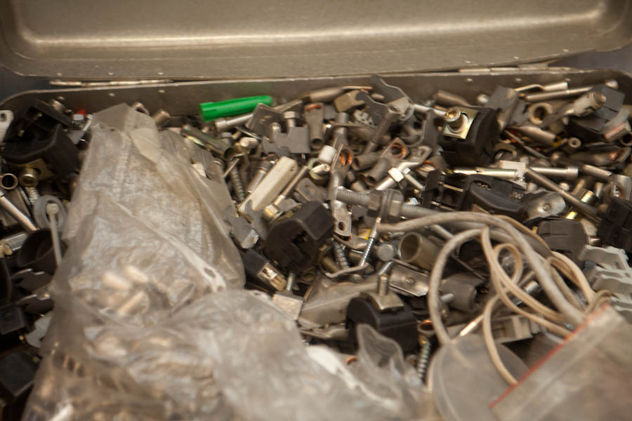
A very important thing for installation: a large suitcase with all sorts of fasteners and fittings for various purposes.
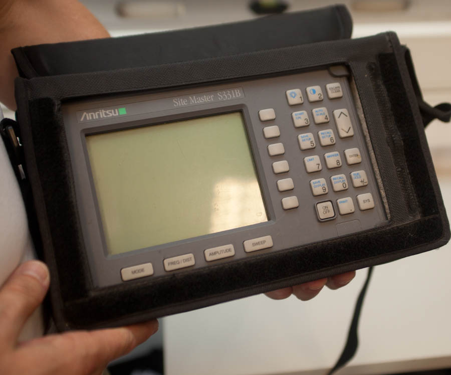
And this is a very useful device for measuring the standing wave ratio in antenna-feeder systems. With it, we check the performance of antennas and feeder paths. It helps us troubleshoot and repair.
About this, as well as about what has changed since the transition to new technologies, I will describe below. Now we will go to the base station in our office. It is not quite normal: on the one hand, it is an operating base station, on the other - it is also used to test and test new equipment.
This is how BS antennas look like; their position can be controlled remotely.
')
Antenna Motor Controller (Top Rack Unit)
Be careful , there are a lot of photo traffic below.
Short educational program
Many believe that the antennas installed on the roof, and are the base station. This is not entirely accurate - they represent one of its elements, specifically, a device for receiving and transmitting a cellular signal from the subscriber to the subscriber, then to the base station itself, to the controller and other control devices.
Here is the signal path (very simplistic):
1) Your signal is received by antennas at one of the sectors of the base station;
2) Passes through the amplifier, where the level of the received and transmitted signal is equalized (from the weak transmitter of the telephone);
3) Enhanced remote controllable radio module;
4) Through the base station goes on to the controller, where the processing and switching takes place;
5) Data is processed and transmitted to voice and packet traffic switches, connecting subscribers to each other and to the Internet.
Photo
Below is a photo of the room with the equipment of base stations. Usually such rooms are much smaller than ours, and in containers for installation in open areas and even less space. In addition to the base station itself, there are many auxiliary equipment in the room, such as a cooling system, an alarm, a fire extinguishing system, and uninterruptible power supplies that the base station can operate for some time without external power supply.
On the right, a cellular network “dinosaur” is looking at us - a wardrobe with a 2G station. In the center - more modern equipment that supports the 3G standard.
Here are the empty controller cells:
Another “exhibit” is fixed on the wall - one of the first base stations intended for organizing communication inside the premises, the so-called micro cells.
Another old device is a packet switching unit, DDF for two megabit streams.
This is where he inserted “elephants” connecting traffic flows. The device is really a bit like an elephant.
But let's look at the working equipment. This is what the old base stations look like from the inside:
On this equipment, the amplifiers are located in the base station itself, using signal transmission to the antennas over thick RF cables. More modern solutions use fiber and antenna units themselves.
Looking at this picture, you can understand what is the difference between the modern base station device (on the right) and what was.
In the second case, the radio modules are installed next to the antennas:
That's just the same radio module in the room. Here it is for the convenience of testing:
Previously, the feeder path was raised to the roof. It is about two of my fingers thick and practically does not bend with your hands. The connectors are large, often oxidized, get wet. Here he is:
And this is a new connection, an optical fiber in an armored cable, it is very flexible and easy to install and maintain:
With the introduction of fiber, several other important benefits emerged: energy consumption decreased by several percent throughout the network (because the unit began to cool naturally outside), copper consumption for cables decreased, plus we began to go less often to remove bullets from the cable. Yes, it sounds ridiculous, but as soon as the hunting season begins, we begin regular failures due to a "shot feeder path". It's much more difficult to get into the optical fiber, because snipers are not yet mature enough, apparently.
And here is another conclusion without an armored braid, look how thin:
It is not always possible to use remote controlled modules (RRU) around the antennas themselves - in the southern regions of free cooling it may not be enough (but this is quite rare). In the north, winter helps a lot. For example, a photo of my colleague from Arkhangelsk, this is a block with an open lid.
Now let's go back to Moscow, go back to our room and look at the next cupboard. These are power supplies.
Below are the uninterruptible power supply (UPS) batteries, in which the base station is able to work for several hours if there are problems with electricity. If this problem occurs, we use the energy of a diesel generator.
Also, the base station can be powered from other sources, such as wind turbines or solar panels. During the restoration of communications after the floods in Krymsk, the generators were very helpful: the emergency team connected them to the station for several hours. During this time, the UPS batteries were charged to a sufficient level to give "rest" to the generator. The cycle was repeated until the city grid was restored.
Base stations use 48 V.
Opposite these cabinets there is a standard 19-inch rack in which several units are installed. So now looks like a modern base station, in this case, 3G and LTE. In addition, we know the antenna motor control unit, with which you can remotely change the electric tilt angle and transmit information to the control server.
The motor control device has been used for several years and has proven to be a reliable device that does not require much attention and time for maintenance.
You can connect to each motor at any base station remotely via a web interface or console and receive data on its status or give control commands. Previously, the antenna tilt angle could be changed only manually using the device shown in this photo.
This is an LTE base station - its control part (second unit on top):
And this is the LNA control unit - a low-noise amplifier. The phone transmitter is weak, so the signal coming from it must be amplified, if possible, without distortion. This unit is just designed for this.
This is one of the devices that is used for testing equipment - the agreed load (a test device that allows you to check some parameters of a base station without putting it on the air):
Now up again! This is how the base station antennas usually look at the city.
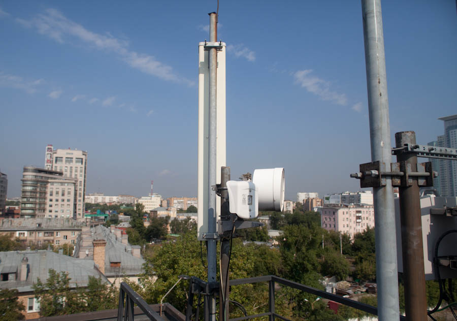
In addition to antennas for transmitting a cellular signal, there is an antenna for transmitting information flows between base stations. This is a radio relay antenna. It is used where there is no possibility of transmitting information between base stations using optical links. There are several ways to transmit information channels. It can be transmitted in any way - from the optical cable and ending with a two-way satellite antenna with a satellite modem (like in our port in Dickson). This is a radio relay antenna:
Optical fiber comes from the BS below and looks like this:
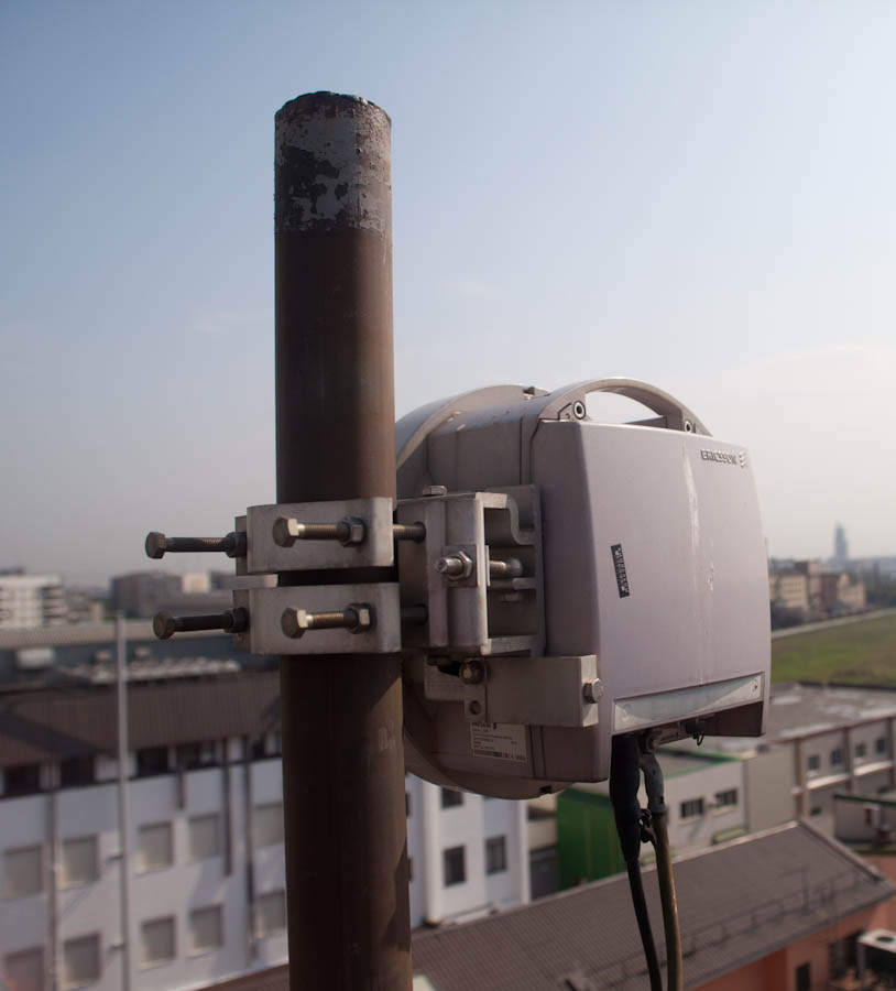
Next, the fiber goes to remote radio-controlled units (transceivers) that are already familiar to you. This is, for example, a three-band antenna. Three antennas of 900, 1800 and 2100 bands are installed in its case. It differs from other antennas in its large size and weight (which makes its maintenance a little difficult). This antenna is equipped with a triple control motor.
Above the antenna you can see the pins. These are lightning rods:
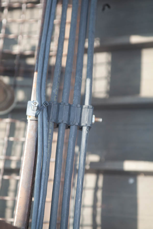
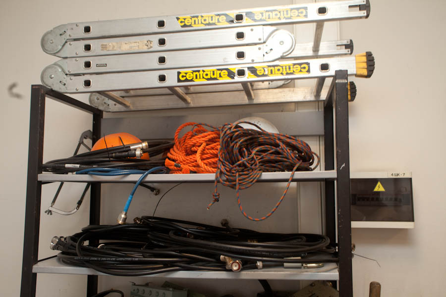
Typically, repair of base stations and scheduled maintenance is done by contractors. But our department also constantly takes part in the repair and maintenance of base stations and antennas, so we also have our own equipment for measuring. In the photo - equipment. Below it are thick black cables - these are feeder jumpers. The feeder is heavy, it bends poorly, it is difficult to connect it. Therefore, such an elastic short adapter is used.
Sometimes it happens that one cable needs to transmit signals to the antenna in several bands, for example, 900 and 2170. Where the second cable cannot be laid for various reasons, a combiner is used. The principle of operation is a multiplexer and a demultiplexer. The quality of the line suffers somewhat, but you have to sacrifice something.
Here are the connectors installed on the feeders.
A very important thing for installation: a large suitcase with all sorts of fasteners and fittings for various purposes.
And this is a very useful device for measuring the standing wave ratio in antenna-feeder systems. With it, we check the performance of antennas and feeder paths. It helps us troubleshoot and repair.
Links
- Here, my colleague has details on the evolution of antennas
- About our first base station and a man in a sweater
- Repeaters and femtocells
- Energy saving on BS , distributed BS architecture and any exotic nutrition.
- The story of the restoration of the network in Krymsk , where several stations were flooded.
- Post about mounting on a closed facility in the north.
Source: https://habr.com/ru/post/192430/
All Articles