Enclosed ecosystem in Russian
Hello, Habr!
Recently I came across an interesting article on the Internet, in terms of gardening, about an Englishman who put a Tradescantia in a jar 53 years ago. He corked a bottle and, after watering 40 years ago, no longer opened it. Ideas came to him out of curiosity. To this day, the plant lives, grows and absorbs oxygen. Tradescantia formed an ecosystem: during photosynthesis, oxygen is formed, the air inside the vessel is moistened and moisture falls out, the fallen leaves rot, releasing CO 2 . But for photosynthesis, you also need light, so you need to constantly push the bottle to the window and unfold it so that the leaves grow evenly. I added some electronics for the houseplant, and this is what came of it.
As already mentioned, in the process of photosynthesis, the most important is light. But not any!
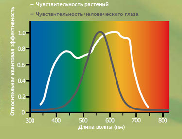
')
For plants, the most important is blue-green and yellow-red. Wavelengths are respectively from 440 to 550 nm and from 600 to 650 nm. I went to the store and bought 4 red, 2 blue and 2 green LEDs (after reading the article on Radiokot). Then he placed them under the lid of the jar, fastening it on a piece of cardboard, and connected them in parallel (for 2 red 1 blue and 1 green).
Since LEDs of different colors of a luminescence have different supply voltage, put resistors.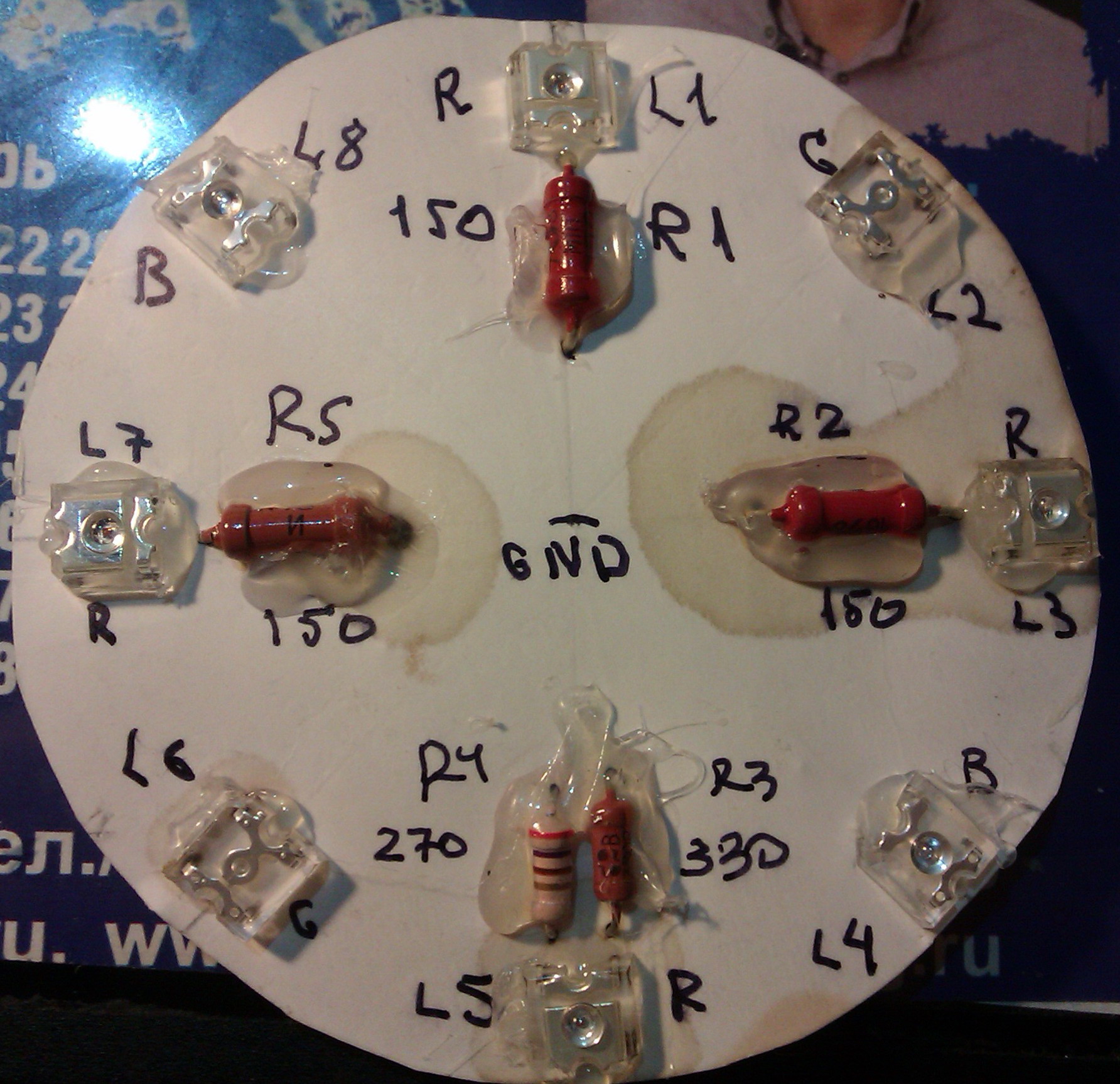 In the lid I made a hole for the wires and strengthened the cardboard box with the LEDs under the lid, after having inserted the wires into the hole. For greater isolation from the outside world, the hole can be sealed.
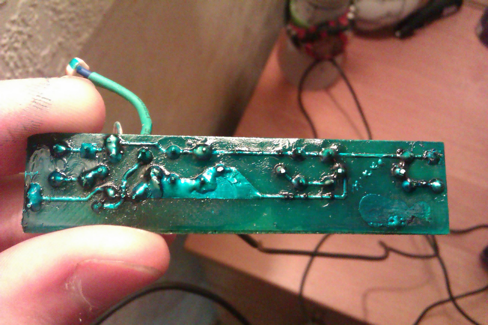
Audit of the lighting module dated 07/01/13.
The module was specially coated with a thick layer of Zaponlak to prevent corrosion of the terminals of the elements and copper on the board.
I have already done the main, that is, the highlighting, so I turn to useful additions.
1. In order for the light to burn only when the plant is in the shade, you need to add a photocell.
Connection diagram: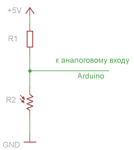
To make the pot completely clever, let's connect the Arduino to it. Analog InPut on the circuit - any analog input from the Arduino. On the PWM (or PWM) output we will hang LEDs, the brightness of which will vary depending on the brightness of the photoresistor. But first, let's find out what values the voltage divider will produce.
In my circuit, I used a photoresistor from the electronic designer of the Contender. He has a shadow resistance of 120 kΩ. The calculation of the resistor R1 is made according to the formula: R
The minimum value of illumination from my divider is about 100 (let's call them conditional units), the maximum is about 755 cu
Knowing these values, you can write a program for the Arduino - controller.
Also note that the maximum current through the Arduine digital Inputs / Outputs should not exceed 40mA .
2. Instead of a digital method for determining the level of illumination, you can use analog. By adding a zener diode and a transistor to the divider, we get everything the same as with the processor, only in a smaller volume. Scheme:
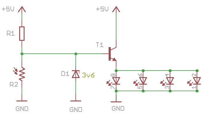
Zener D1 - any power at 3.6 V. T1 transistor - any NPN.
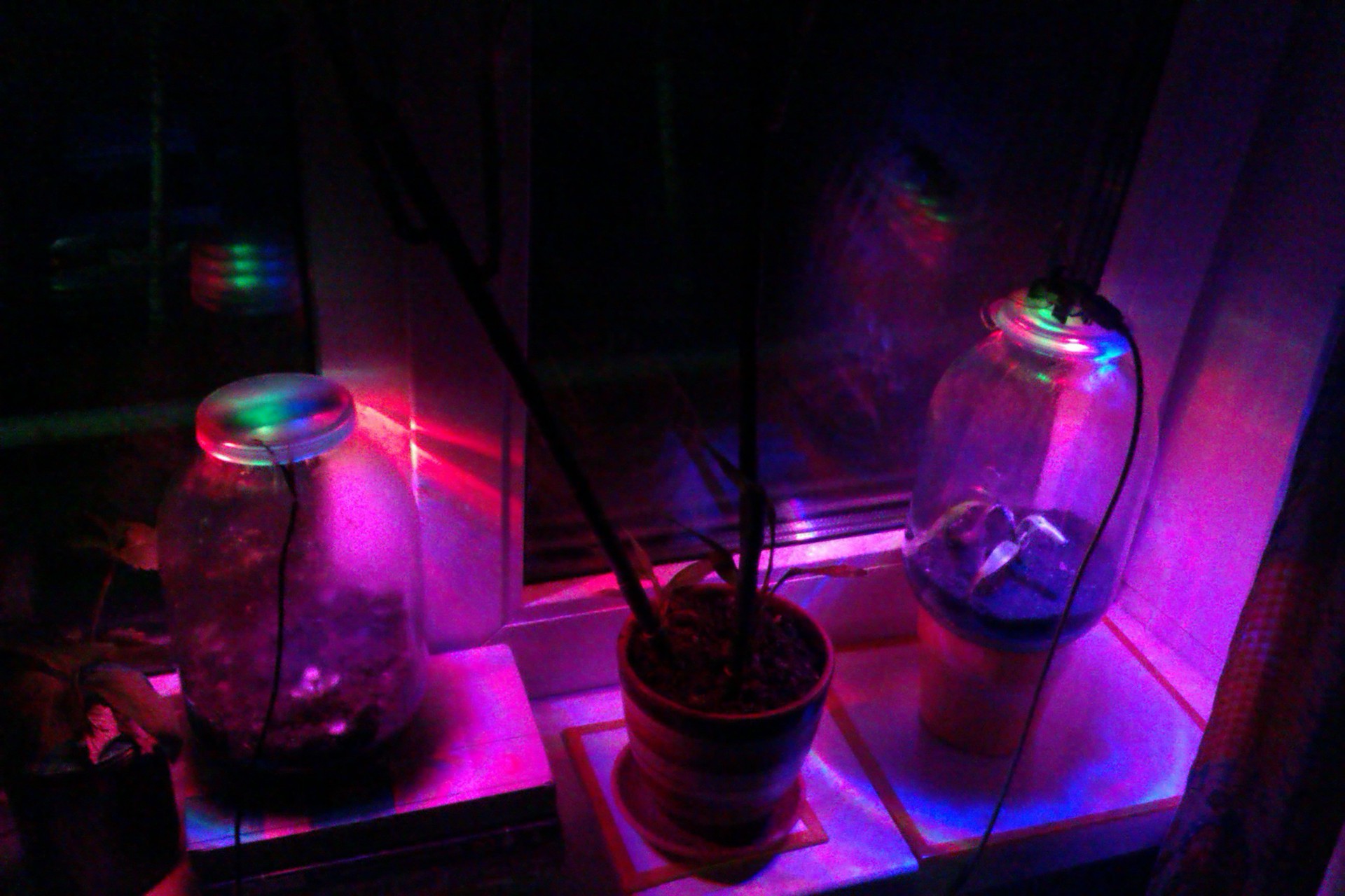
PS It would look much better if the wires did not stick out. The design itself will be more technological if we put a coil at the bottom of the can and power the backlight without wires (like wireless charging from phones ).
The photo below shows the first experimental bank. The plant was planted in it 01.06.13.

Subsequently, it was decided to refuse this bank, since the plant did not have enough room for growth (also, the steel cover, with a high degree of probability, in 40 years of use, will rust :)).
Instead of a small liter jar, the plants were planted in large - 3-liter. The cover was also replaced with a polyethylene one.
PSS Landing date: 30.06.2013 (01.07.13 a bank was opened to replace the lighting module).
Photo 1: 07/10/13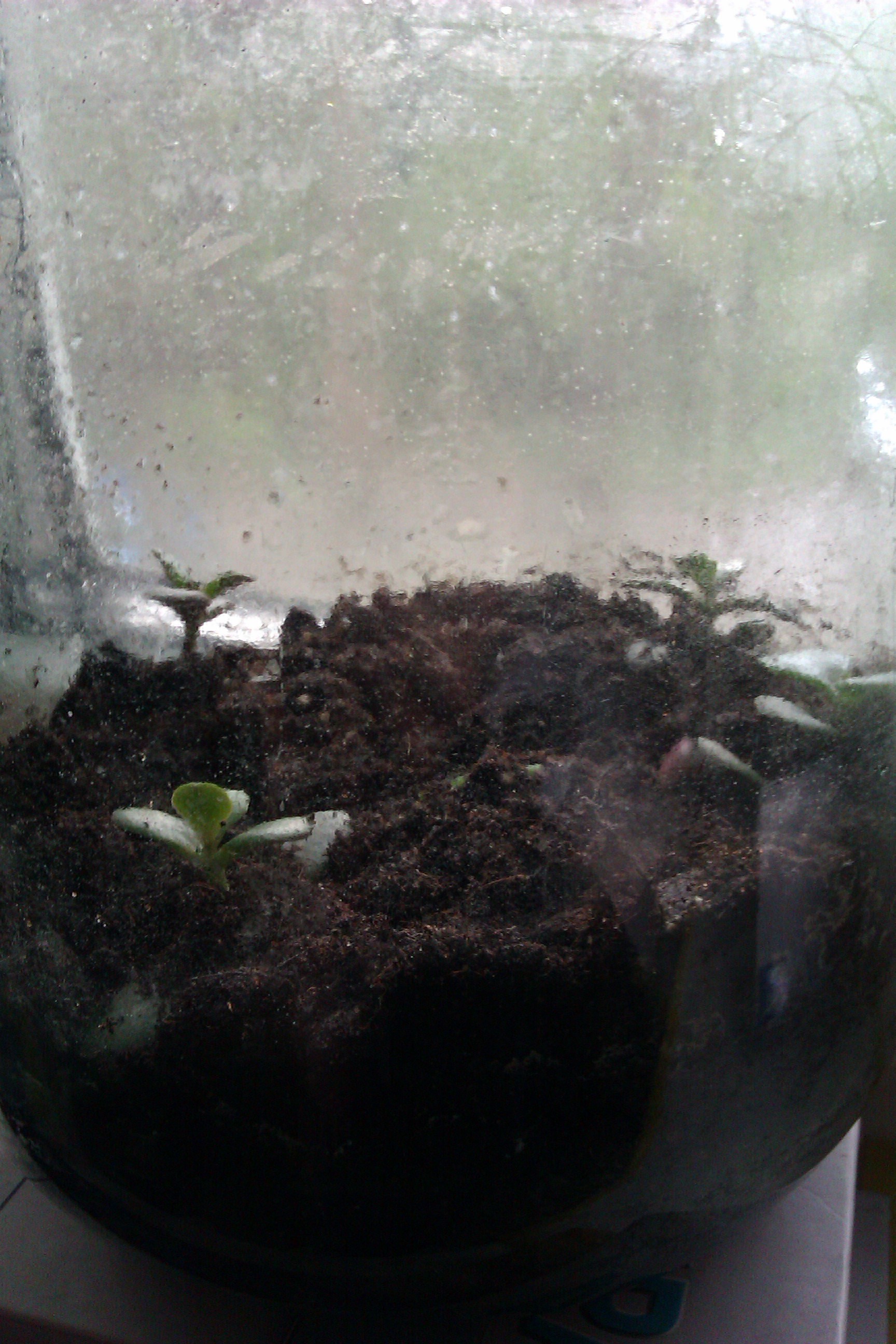
Photo 2: 07/17/13. The photo below shows how vegetation began to appear on the walls. This indicates that the simplest plant species also feel well in the system.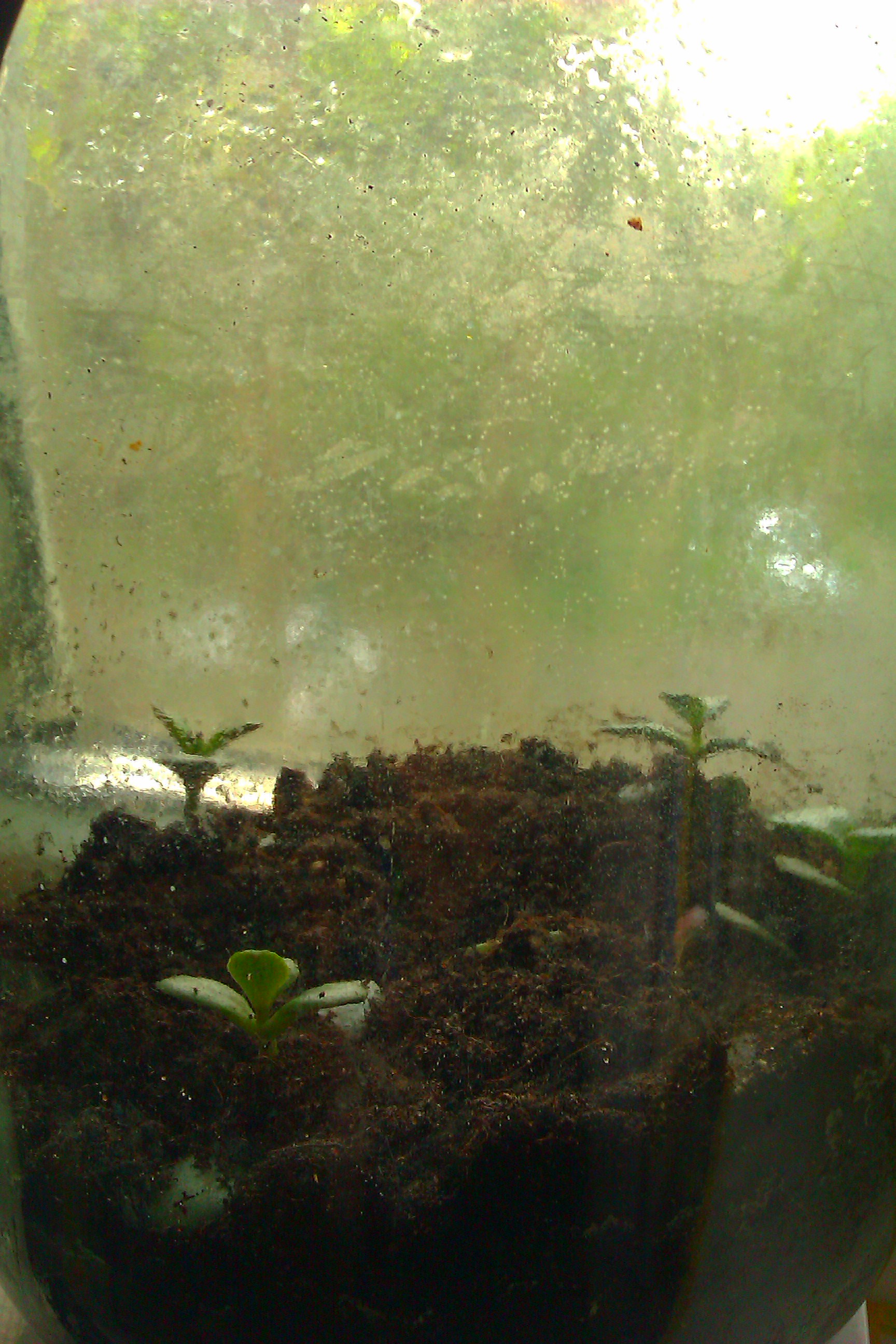
Photo 3: 09/02/13
Also, for the experiment, a mandarin bone (previously not kept in a wet gauze, etc.) was planted in a money tree jar. As you can see in the photo above, it is now sprouted.
With the accumulation of experimental data, information will be laid out here.
Recently I came across an interesting article on the Internet, in terms of gardening, about an Englishman who put a Tradescantia in a jar 53 years ago. He corked a bottle and, after watering 40 years ago, no longer opened it. Ideas came to him out of curiosity. To this day, the plant lives, grows and absorbs oxygen. Tradescantia formed an ecosystem: during photosynthesis, oxygen is formed, the air inside the vessel is moistened and moisture falls out, the fallen leaves rot, releasing CO 2 . But for photosynthesis, you also need light, so you need to constantly push the bottle to the window and unfold it so that the leaves grow evenly. I added some electronics for the houseplant, and this is what came of it.
Stage One
As already mentioned, in the process of photosynthesis, the most important is light. But not any!
')
For plants, the most important is blue-green and yellow-red. Wavelengths are respectively from 440 to 550 nm and from 600 to 650 nm. I went to the store and bought 4 red, 2 blue and 2 green LEDs (after reading the article on Radiokot). Then he placed them under the lid of the jar, fastening it on a piece of cardboard, and connected them in parallel (for 2 red 1 blue and 1 green).
Since LEDs of different colors of a luminescence have different supply voltage, put resistors.
In the lid I made a hole for the wires and strengthened the cardboard box with the LEDs under the lid, after having inserted the wires into the hole. For greater isolation from the outside world, the hole can be sealed. Audit of the lighting module dated 07/01/13.
The module was specially coated with a thick layer of Zaponlak to prevent corrosion of the terminals of the elements and copper on the board.
Stage Two
I have already done the main, that is, the highlighting, so I turn to useful additions.
1. In order for the light to burn only when the plant is in the shade, you need to add a photocell.
Connection diagram:
To make the pot completely clever, let's connect the Arduino to it. Analog InPut on the circuit - any analog input from the Arduino. On the PWM (or PWM) output we will hang LEDs, the brightness of which will vary depending on the brightness of the photoresistor. But first, let's find out what values the voltage divider will produce.
Code
int sensor =0; // Arduino A0 void setup() { Serial.begin(9600); } void loop() { Serial.println(analogRead(sensor)); delay(1000); // } In my circuit, I used a photoresistor from the electronic designer of the Contender. He has a shadow resistance of 120 kΩ. The calculation of the resistor R1 is made according to the formula: R
1 = V in * R 2 : V out -R 2 ; V in on the scheme - + 5V, V out - “to the analog input of the Arduino” (I hope everyone well remembers the order of actions: first, the actions of the first degree - multiplication and division, and then the second - addition and subtraction). Also, it should be remembered that the resistance of the photoresistor may vary nonlinearly .The minimum value of illumination from my divider is about 100 (let's call them conditional units), the maximum is about 755 cu
Knowing these values, you can write a program for the Arduino - controller.
Code
int sensor = 0; // 0 int ledPin = 9; // 9 void setup () { analogReference(DEFAULT); pinMode(ledPin, OUTPUT); //Serial.begin(9600); // .. . } void loop() { int val = analogRead(sensor); val = constrain(val, 130, 755); // . // < 130, 130, > 755, 755. int ledLevel = map(val, 130, 755, 0, 255); // .. // 8- . analogWrite(ledPin, ledLevel); // Serial.println(analogRead(ledLevel)); // .. . } Also note that the maximum current through the Arduine digital Inputs / Outputs should not exceed 40mA .
2. Instead of a digital method for determining the level of illumination, you can use analog. By adding a zener diode and a transistor to the divider, we get everything the same as with the processor, only in a smaller volume. Scheme:
Zener D1 - any power at 3.6 V. T1 transistor - any NPN.
PS It would look much better if the wires did not stick out. The design itself will be more technological if we put a coil at the bottom of the can and power the backlight without wires (like wireless charging from phones ).
The photo below shows the first experimental bank. The plant was planted in it 01.06.13.
Subsequently, it was decided to refuse this bank, since the plant did not have enough room for growth (also, the steel cover, with a high degree of probability, in 40 years of use, will rust :)).
Instead of a small liter jar, the plants were planted in large - 3-liter. The cover was also replaced with a polyethylene one.
PSS Landing date: 30.06.2013 (01.07.13 a bank was opened to replace the lighting module).
Photo 1: 07/10/13
Photo 2: 07/17/13. The photo below shows how vegetation began to appear on the walls. This indicates that the simplest plant species also feel well in the system.
Photo 3: 09/02/13
Also, for the experiment, a mandarin bone (previously not kept in a wet gauze, etc.) was planted in a money tree jar. As you can see in the photo above, it is now sprouted.
With the accumulation of experimental data, information will be laid out here.
List of sources
- Video tutorials on Arduino by Jeremy Bloom (Jeremy Blum) in the translation of Amperka (amperka.ru).
- Phytolamp
Source: https://habr.com/ru/post/192168/
All Articles