Create autonomous robot Frank. Part two
It took a little time and I have significant progress. If you have not read the background - welcome to “Creating an Autonomous Robot Frank. Part One .
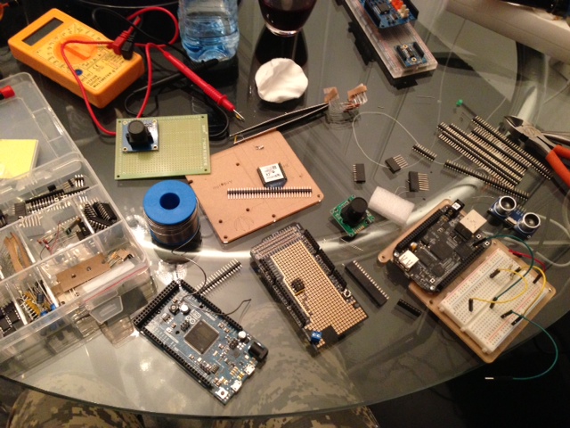
So, in the first part I assembled a platform based on Lego Technic and HiTech servo motors. Having ditched the only shield for prototyping for Arduino, I waited for me to get a replacement, plus a new solder, instead of the environmentally friendly one that I had - without any lead. Also, I had at my disposal a pair of XBee for wireless communication, with which it was necessary to figure out Arduino Due, which I wanted to experiment with.
')
It turns out that lead-free solder is very difficult to solder, so I ordered another S-Sn60Pb39Cu2 2.5% Flux from Felder. The difference is amazing. It melts immediately and fits perfectly on the contacts. This has accelerated the creation of the board many times.
In order. At first I made my shield for controlling servo motors. Experiments with breadboard, of course, are required to make sure that everything works, but it always looks disgusting. In order to solder the board, I ordered a prototyping board from DFRobot for the Arduino Mega , which fit perfectly with the Arduino Due. To control the servo-motors, it is necessary to connect the yellow wire of the motor to the PWM outputs of the Arduino via a resistor. It should be noted that the Arduino Due 12 PWM outputs, which allows you to connect a lot of servo-motors without additional controllers. In practice, of course, this must be checked. It is possible that the board does not have enough timers to smoothly control 12 motors. Plus, the ground must be connected to the battery and the battery ground should be combined with the ground from the Arduino. I wrote about this in more detail in the previous article. The board was clean enough and there was still a lot of room for other components - for example XBee.
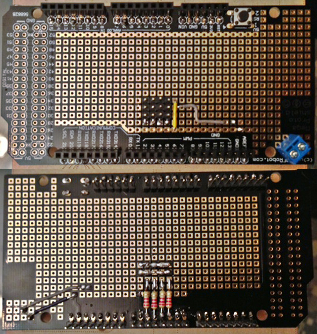
As you can see, the board has four outputs for servo motors and a separate input for external power. It looks quite clean and very convenient to connect.
That's all, the simple thing is over and the experiments with XBee began. Naturally, taking them out of the box and plug, nothing worked. An Internet search gave only a couple of articles about the fact that they first need to be configured. Software for configuring XBee, of course, is written under Windows, and I have a Mac. What to do? Finally, I found an article that describes how this can be done through a serial interface.
Included with the XBee are two small cards, which plug in wireless modules. Both boards can be connected to the Arduino, pre-soldering the legs and using the breadboard. One of the boards has a USB output (USB-to-Serial).

Since I was planning to interact and exchange information between Frank and my laptop, I started by writing a simple program to communicate with the XBee via a serial interface. To do this, I downloaded the latest version of Qt (5.1), in which the QSerialPort class appeared, allowing you to communicate with external devices via the serial port. The program looks like a terminal so far, but in the future I will expand it to fully manage Frank via the XBee connected to my computer. All that the program is doing at the moment - it sends and receives messages on the serial port, which must be entered manually.

Source Code Since everything is written using Qt, it should work on any computer. Compiling requires Qt5.1. The project file was generated by QtCreator.
First you need to determine the name of the XBee connected to the computer. To do this, look at the list of devices in the / dev folder and look for something similar to tty.usbserial-A9014B88 (as it is called by me). In the code, we change the line “port = new QSerialPort (" usbserial-A9014B88 ");" your device name (without "tty.").
If you yourself have not configured the XBee before, then you need to change “port-> setBaudRate (19200);” to 9600 or just comment out this line, since this speed is by default written in the device. Next, run the program by connecting the first module and enter "+++". Three pluses wake the device for further commands. In response, you should receive "OK", which will be displayed in the terminal window. After a while (I still did not understand what) the device goes into sleep mode, so do not tighten it with the other commands. In order to wake him up again, send back three plus points.
Next, send the configuration to the first module. "ATID4000, DH0, DL1, MY0, BD4, WR, CN". This changes its ID to 4000 (can be any number), communication speed to 19200 and its address to “0”. For two devices to communicate with each other, their ID must match, and for one device the address must be “0” and the other one “1”. After you send this command, you should come back 7 "OK" (or so). If something goes wrong, then one of “OK” will be “ERROR”.
Now we can pull the chip out of the board and put the second chip there, having previously disconnected the board from the computer. Repeating all the same commands, except that MY0 should be MY1 "ATID4000, DH0, DL1, MY1, BD4, WR, CN". Do not forget that now both devices operate at a frequency of 19200. Therefore, with further connection in the source code of the program, you must specify this speed when connecting - “port-> setBaudRate (19200);”.
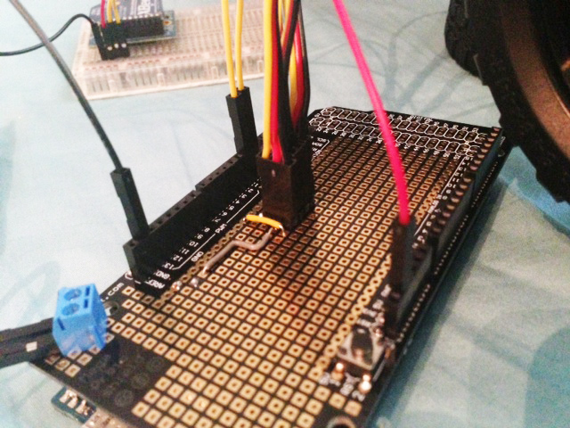
Now it remains to connect one device to the computer (you can simply leave the one that is already connected), and the second to the Arduino. I will again resort to the prototyping board, but most likely, today I solder XBee to my prototype shield.
The connection is quite simple - it is necessary to connect VSS to the ground of the Arduino, VCC from 3.3V, DOUT to the RX (port 0 to Arduino Due), and DIN to TX (1 port). On other boards, there may be other ports - just find the RX and TX (serial interface). Now we need to make them send messages to each other.
Again, everything was not so simple. SofwareSerial have not yet ported to ArduinoDue - it means that you can use only the hardware interface, and most of the examples on the Internet simply do not work. The fact that I have an XBee Series1 has reduced the number of examples available on the Internet to a minimum. This library helped a lot . If you have Arduino Due, then you need to download "xbee-arduino-0.3.zip", since version 0.4 works through SoftwareSerial. Install the library in Arduino (Sketch-> Import Library-> Add Library) and specify the folder in which lies what you downloaded and unzipped. After that click (Sketch-> Import Library-> XBee), and you will get the line "#include <XBee.h>".
Now we can load this sketch into the Arduino.
#include <XBee.h> // XBEE Code XBee xbee = XBee(); unsigned long start = millis(); uint8_t payload[] = { 0, 0 }; Tx16Request tx = Tx16Request(0x4000, payload, sizeof(payload)); void setup() { // XBee Code Serial.begin(19200); xbee.setSerial(Serial); } void loop() { // XBee Code if (millis() - start > 15000) { // Wait for boot and connection to establish xbee.send(tx); } delay(1000); } uint8_t payload[] = { 0, 0 }; - this is an array of data that XBee will send.Tx16Request tx = Tx16Request(0x4000, payload, sizeof(payload)); - This is a request to send information. Pay attention to 0x4000 - this value should correspond to the ID that we set earlier when setting up a pair of XBee.All he does is send two characters with the ASCII code “0” to another XBee. By running iFrank, you can see how empty characters appear in the terminal window. This is certainly not so interesting, but the goal was to check the connection between the modules. By the next article, I hope to understand the camera, the exchange of information between the computer and the Arduino, solar panels, as well as write controls on Qt.
Assembly now everything looks like this:

Source: https://habr.com/ru/post/191902/
All Articles