Calculation of the booster circuit for maximum battery power
The purpose of this article is to show how it is possible to calculate the mode of operation of the booster (from the English. Booster) voltage converter (DCB) of the direct current so as to extract the maximum possible power from the battery with a constant internal resistance.
Often, in practice, integrated circuits (ICs) are used, in which the received power is monitored at the hardware level (for example, SPV1040), but the price of such devices is quite high.
There are cases when you create a simple device on a battery, for example - an LED flashlight. I want the battery to be used rationally, but the cost of this should be adequate.
For simple circuits, where the load resistance and the internal resistance of the battery are known in advance, there is a method for calculating the operating mode of a booster voltage converter.
We will understand what kind of a converter.
The general scheme of a typical BPN is depicted in the figure:

')
Here are shown n batteries with their own booster units. In the particular case, you can do it alone.
When the key is closed, the current rushes to "minus". The current through the inductance increases (but it does not have to reach the magnitude of the short-circuit current, otherwise the energy will be wasted), the inductance accumulates energy.
Then the key is opened. The current through the inductance can not change instantly, it creates an additional EMF, giving the accumulated early energy to the circuit. So the voltage at the load at this point is greater than the battery gave.
A diode is needed so that the current from the capacitor at the output does not go back. Most often it is a schottky diode with a small voltage drop.
From the school course of physics, we know that the maximum power of the current source with non-zero internal resistance is achieved with equal input and external resistance.
We write the main currents of the circuit:

Here emf is the battery emf, r is the internal resistance, Rn is the load resistance.
Without going into details of the output, I will give the formulas for increasing and decreasing the current:
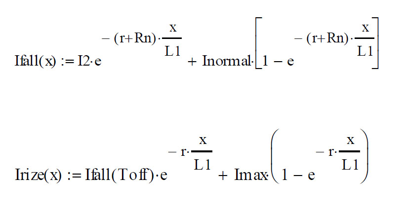
After some transformations we get the average values:
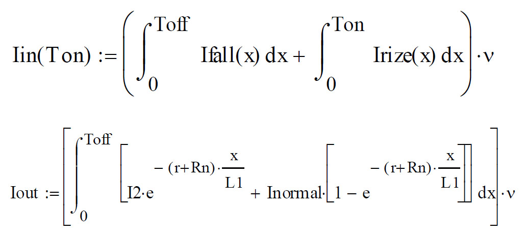
If the following conditions are met, the maximum power will be achieved:

This system can be solved numerically in mathematical programs, for example: MathCad, MathLab.
1. Use this method only for a known constant value Rin and a known load resistance;
2. Parallel to the battery, you need to turn on the capacitor;
3. After this scheme, use the DC-DC module;
4. It is best to install a cheap weak controller with support for generating PWM, for example: the ATtiny series, the ATmega series, you can find something from the PICs;
5. Because the circuit works as a current generator; it is possible to combine several blocks onto a common capacitor without matching.
Often, in practice, integrated circuits (ICs) are used, in which the received power is monitored at the hardware level (for example, SPV1040), but the price of such devices is quite high.
There are cases when you create a simple device on a battery, for example - an LED flashlight. I want the battery to be used rationally, but the cost of this should be adequate.
For simple circuits, where the load resistance and the internal resistance of the battery are known in advance, there is a method for calculating the operating mode of a booster voltage converter.
Booster voltage converter
We will understand what kind of a converter.
The general scheme of a typical BPN is depicted in the figure:
')
Here are shown n batteries with their own booster units. In the particular case, you can do it alone.
When the key is closed, the current rushes to "minus". The current through the inductance increases (but it does not have to reach the magnitude of the short-circuit current, otherwise the energy will be wasted), the inductance accumulates energy.
Then the key is opened. The current through the inductance can not change instantly, it creates an additional EMF, giving the accumulated early energy to the circuit. So the voltage at the load at this point is greater than the battery gave.
A diode is needed so that the current from the capacitor at the output does not go back. Most often it is a schottky diode with a small voltage drop.
Maximum power
From the school course of physics, we know that the maximum power of the current source with non-zero internal resistance is achieved with equal input and external resistance.
We write the main currents of the circuit:
Here emf is the battery emf, r is the internal resistance, Rn is the load resistance.
Without going into details of the output, I will give the formulas for increasing and decreasing the current:
After some transformations we get the average values:
If the following conditions are met, the maximum power will be achieved:
This system can be solved numerically in mathematical programs, for example: MathCad, MathLab.
Recommendations for practical use:
1. Use this method only for a known constant value Rin and a known load resistance;
2. Parallel to the battery, you need to turn on the capacitor;
3. After this scheme, use the DC-DC module;
4. It is best to install a cheap weak controller with support for generating PWM, for example: the ATtiny series, the ATmega series, you can find something from the PICs;
5. Because the circuit works as a current generator; it is possible to combine several blocks onto a common capacitor without matching.
Source: https://habr.com/ru/post/191428/
All Articles