Binary watch with alarm clock on Atmega48 (EvILeg-1124)
To build such things as binary watches come in several ways, in my opinion. Or just a desire to have such an unusual toy, either for general development or for training, which is necessary for professional growth in a chosen field. So why not combine business with pleasure, given that there is a lot of useful material online.
The basis for the development of the idea of assembling binary watches was the article published on March 9, 2012, entitled “Binary clock do-it-yourself (Mega32, DS1307)” . I hasten to thank the author of the article, since it served as the starting point for my variation on the theme of binary clocks.
The principal difference is that the clock shows time not in the purely binary number system, but in the binary-decimal representation. That is, the highest tetrade byte is responsible for tens of hours / minutes / units, and the youngest one, respectively. Thus, the appearance of the clock becomes the same as the appearance of the widget of the same name in the free KDE desktop environment . Also, the functionality of the clock is extended by the alarm clock, so the clock is not only able to perform a direct function of timing, but also an equally useful function of awakening the owner (Fig. 1).
')
This watch model was given the name EvILeg-1124.
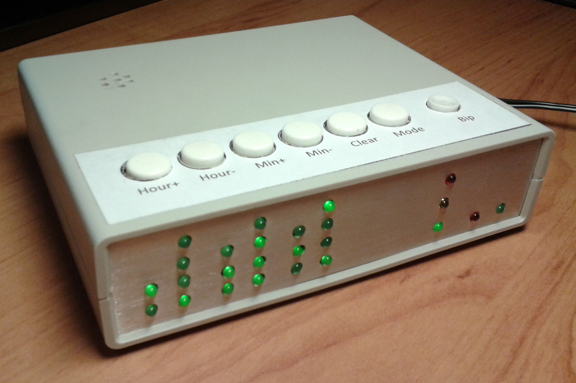
Figure 1 - The appearance of the clock EvILeg-1124
Clock
To implement the functions of time counting, the DS1307 chip (Fig.2) was powered by a CR2032 battery, however this is not surprising, considering that this chip is the most optimal for developing skills with microcontrollers when solving a similar task, like assembling clocks. The advantage of this microchip is that there is a large amount of material on the Internet to connect this chip to AVR microcontrollers on the I2C bus, on the basis of which familiarity with this serial bus protocol takes place, on which up to 128 devices can be installed, which will be very useful when developing a large project.
Figure 2 - DS1307 pinout pinout
Schematic solution
Atmega48PU was taken as the controlling microcontroller, which has a sufficient number of legs (28, the option was taken in a DIP package) and flash memory, although it still seems somewhat redundant for this project, since with 4 KB of memory available, only 1124 bytes were used, which is reflected in the name of this watch model. Atmega48 pinout is shown in Figure 3.
Figure 3 - Atmega48 pinout in DIP package
The following functions were assigned to the microcontroller legs:
The schematic diagram and the boards were prepared in the DipTrace development package.
A schematic diagram showing the circuit design of the implementation of the described functional is shown in Figure 4.

Figure 4 - Schematic diagram of the clock
Software solution
The firmware of the microcontroller is written entirely in the Assembler programming language in the Atmel Studio 6.1 integrated development environment. The microcontroller firmware was implemented by the ATAVRISP2 programmer.
The logic of the firmware is as follows:
When turned on, the microcontroller polls the clock and immediately starts displaying the time on the display. Interrupt INT0, which is activated by a pulse from the output of the SQW / OUT chip DS1307, time is read once every one second. The display is scanned by timer interrupt 0. Also on the clock panel there are LEDs of the modes (green, yellow and red; these LEDs are highlighted in Figure 5), each of which is responsible for its own clock behavior mode. This is reflected in the reaction of the clock to pressing the buttons.

Figure 5 - Front Panel Appearance
Watch behavior modes are as follows:
To handle the buttons, timer 1 is used, which sets a delay of approximately 1 second, during which the microcontroller does not respond to signals sent to the output with an INT1 interrupt, which allows you to eliminate button bounce and program the DS1307 time and alarm time setting that is more comfortable for perception.
Clock assembly
The fabrication of the boards and the soldering of the elements will not be cited in the article, since there are more worthy articles on this topic in the network.
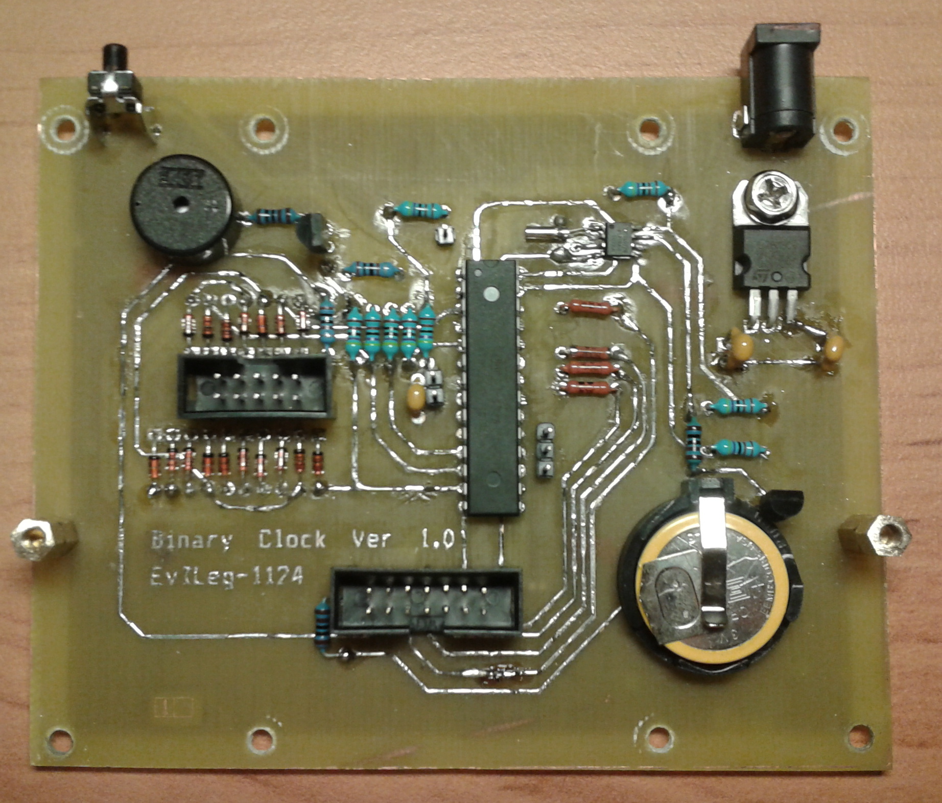
The clock is made up of three boards:
The watches are assembled in a conventional case for REA, which can be bought at a store specializing in electronics.
In the process of assembling and debugging the clock, there were also problems with the power supply, namely, the purchase of an unsuccessful unstabilized power supply, which, with the stated nominal value of 4.5V, actually gave out 8.32V, as a result of which the test microcontroller failed. After that, it was decided to assemble a simple power supply scheme on a voltage stabilizer 7805 (the culprit of the brave microcontroller who died by death is presented in the last photo). However, now the clock can be powered with a constant voltage from 5 to 30 volts.


Project files
The source archive of the project from Atmel Studio and DipTrace, the hex file, the printed circuit boards and the circuit diagram are converted to jpeg / rar and uploaded as a photo showing the LED.
Windows users need to open the picture in the Winrar program to get the contents of the archive
Conclusion / Epilogue
A demonstration of the operation of the device is shown in the following video.
To implement the project, material from various sources was used, but the greatest amount of useful material was drawn from the resource “Electronics for All” , for the existence of which I express gratitude to its owner.
This project will be most useful to those who study the programming of microcontrollers at Assembler, since the program code is written completely in this programming language and the comments to the program code are given in the most detailed form, that problems with understanding the process should not arise.
The basis for the development of the idea of assembling binary watches was the article published on March 9, 2012, entitled “Binary clock do-it-yourself (Mega32, DS1307)” . I hasten to thank the author of the article, since it served as the starting point for my variation on the theme of binary clocks.
The principal difference is that the clock shows time not in the purely binary number system, but in the binary-decimal representation. That is, the highest tetrade byte is responsible for tens of hours / minutes / units, and the youngest one, respectively. Thus, the appearance of the clock becomes the same as the appearance of the widget of the same name in the free KDE desktop environment . Also, the functionality of the clock is extended by the alarm clock, so the clock is not only able to perform a direct function of timing, but also an equally useful function of awakening the owner (Fig. 1).
')
This watch model was given the name EvILeg-1124.
Figure 1 - The appearance of the clock EvILeg-1124
Clock
To implement the functions of time counting, the DS1307 chip (Fig.2) was powered by a CR2032 battery, however this is not surprising, considering that this chip is the most optimal for developing skills with microcontrollers when solving a similar task, like assembling clocks. The advantage of this microchip is that there is a large amount of material on the Internet to connect this chip to AVR microcontrollers on the I2C bus, on the basis of which familiarity with this serial bus protocol takes place, on which up to 128 devices can be installed, which will be very useful when developing a large project.
Figure 2 - DS1307 pinout pinout
Schematic solution
Atmega48PU was taken as the controlling microcontroller, which has a sufficient number of legs (28, the option was taken in a DIP package) and flash memory, although it still seems somewhat redundant for this project, since with 4 KB of memory available, only 1124 bytes were used, which is reflected in the name of this watch model. Atmega48 pinout is shown in Figure 3.
Figure 3 - Atmega48 pinout in DIP package
The following functions were assigned to the microcontroller legs:
- Leg # 1 - is responsible for resetting the RESET controller by default (restarting the controller if it hangs);
- Leg number 2 - is responsible for connecting the alarm clock "beeper";
- Leg number 3 - is responsible for the activation of the alarm;
- Leg # 4 is connected to the output of the DS1307 chip, on which a 1 Hz signal is generated, on the falling front of which the INT0 interrupt present on this leg of the microcontroller is working. This interrupt is the time reading from the chip DS1307;
- Leg # 5 is responsible for testing the INT1 interrupt that is present on this leg of the microcontroller. This interrupt is responsible for processing the six buttons connected to legs # 11, 12, and 13. The buttons are polled at a low level on this foot;
- The legs number 11, 12, 13 - as mentioned above, are responsible for the buttons of the clock. Each button generates its own identification code, according to which the INT1 interrupt handler decides what action must be taken;
- Legs №9, 14-19, 23-26 - are responsible for the dynamic LED indication, namely the display of hours / minutes / seconds and the operating modes of the clock;
- Feet # 27, 28 - are responsible for data exchange with the DS1307 chip via the I2C bus, due to the hardware implementation of the TWI interface on these feet.
(TWI (Two Wire Interface) or TWSI (Two Wire Serial Interface) is essentially the same I2C bus, but uses a different name for licensing reasons)
The schematic diagram and the boards were prepared in the DipTrace development package.
A schematic diagram showing the circuit design of the implementation of the described functional is shown in Figure 4.
Figure 4 - Schematic diagram of the clock
Software solution
The firmware of the microcontroller is written entirely in the Assembler programming language in the Atmel Studio 6.1 integrated development environment. The microcontroller firmware was implemented by the ATAVRISP2 programmer.
The logic of the firmware is as follows:
When turned on, the microcontroller polls the clock and immediately starts displaying the time on the display. Interrupt INT0, which is activated by a pulse from the output of the SQW / OUT chip DS1307, time is read once every one second. The display is scanned by timer interrupt 0. Also on the clock panel there are LEDs of the modes (green, yellow and red; these LEDs are highlighted in Figure 5), each of which is responsible for its own clock behavior mode. This is reflected in the reaction of the clock to pressing the buttons.
Figure 5 - Front Panel Appearance
Watch behavior modes are as follows:
- Mode №1 - the green LED is on, in this mode only two buttons respond to external influences, namely, the alarm button and the Mode button;
- Mode №2 - the yellow LED is on, in this mode all buttons respond to external influences and the time of the real-time clock itself (RTC chip) is adjusted, of course, the clock is set in real time without stopping;
- Mode number 3 - the top red LED is on, in this mode all buttons respond to external influences and the alarm time is set, the configured time is recorded in the non-volatile EEPROM memory, therefore, in the event of a power outage, the time set on the alarm clock will not fail ;
- Mode No. 4 - the green and lower red LEDs are lit, in this mode the alarm is activated with the Bip button, while no button reacts to external influences, except for the Bip button itself, which is the only one with a latching button.
To handle the buttons, timer 1 is used, which sets a delay of approximately 1 second, during which the microcontroller does not respond to signals sent to the output with an INT1 interrupt, which allows you to eliminate button bounce and program the DS1307 time and alarm time setting that is more comfortable for perception.
Clock assembly
The fabrication of the boards and the soldering of the elements will not be cited in the article, since there are more worthy articles on this topic in the network.
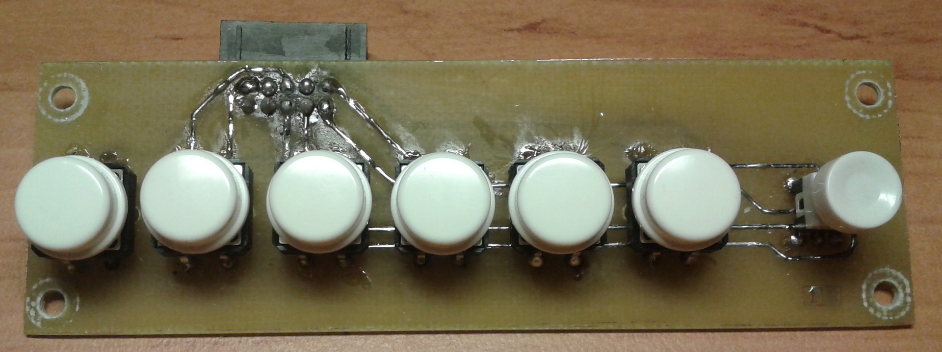
The clock is made up of three boards:
- The first one is the main board on which the microcontroller is located, the DS1307 clock and the entire main piping of the microcontroller;
- The second is a board with LEDs;
- The third one is a board with clock control buttons;
The watches are assembled in a conventional case for REA, which can be bought at a store specializing in electronics.
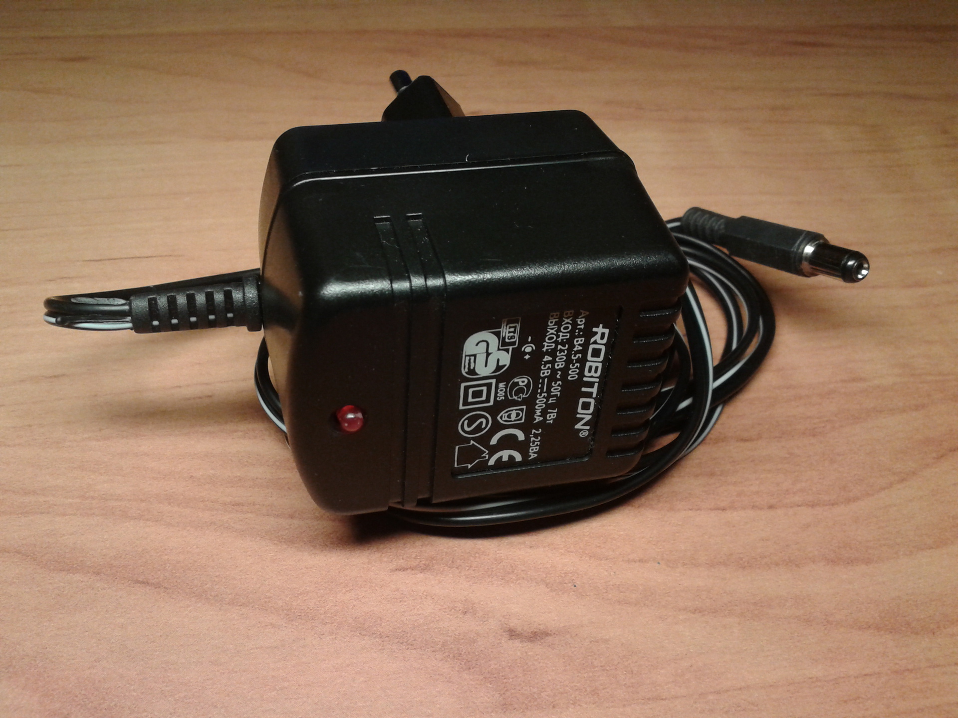
In the process of assembling and debugging the clock, there were also problems with the power supply, namely, the purchase of an unsuccessful unstabilized power supply, which, with the stated nominal value of 4.5V, actually gave out 8.32V, as a result of which the test microcontroller failed. After that, it was decided to assemble a simple power supply scheme on a voltage stabilizer 7805 (the culprit of the brave microcontroller who died by death is presented in the last photo). However, now the clock can be powered with a constant voltage from 5 to 30 volts.
Project files
The source archive of the project from Atmel Studio and DipTrace, the hex file, the printed circuit boards and the circuit diagram are converted to jpeg / rar and uploaded as a photo showing the LED.
Windows users need to open the picture in the Winrar program to get the contents of the archive
Conclusion / Epilogue
A demonstration of the operation of the device is shown in the following video.
To implement the project, material from various sources was used, but the greatest amount of useful material was drawn from the resource “Electronics for All” , for the existence of which I express gratitude to its owner.
This project will be most useful to those who study the programming of microcontrollers at Assembler, since the program code is written completely in this programming language and the comments to the program code are given in the most detailed form, that problems with understanding the process should not arise.
Source: https://habr.com/ru/post/190830/
All Articles