Do-it-yourself AVR LAN tester
The problem of testing a newly laid local network is always relevant. Once I got into the hands of a piece of hardware called the “Rapport II”, which, generally speaking, is a tester for CCTV systems, but it also knows how to twist a pair. That piece of iron had already died a long time ago, but the impression was left: when testing a twisted pair, it showed not just a polarity reversal and unplugging, but an exact crimping pattern! For example, for a crossover, it looked 1 → 3, 2 → 6, 3 → 1, and so on.
But to pay about 800 non-Russian rubles for a device in which I really will use only one function? Dismiss! How does it work, maybe it's easier to do it yourself? Google in hand, and ... sheer disappointment. The search output consists of 80% of the flashing lights with the LEDs on the shift register / AVR / PIC / its own version, and 20% of the profound discussions of forum gurus on the topics “buy% name_cruise_leaning% and don’t worry”. Therefore, I want to offer the habrasoobshchestvu its solution to this problem in the style of DIY. Anyone interested - I ask under the cat (carefully, a certain amount of photos!).
Determining the exact cable crimping pattern is necessary.
All information is displayed by the tester. No flashing LEDs on the counterpart. Suppose that the counterpart is in the hands of a monkey, and not even a circus one, and only thanks to the latest technologies did the monkey learn to use a perforator and cross the cable in the sockets. Or, speaking a little more scientifically: the reciprocal part is completely passive.
Principle of operation: the counterpart is a set of resistances of various denominations. Let's measure them. Knowing their ratings and decoupling the mating part, we can find out exactly how the cable is crossed. Below is a diagram of the device (all illustrations are clickable). Specific denominations of resistances were chosen rather in view of the presence in the store than consciously, although it turned out to be a piece of the Fibonacci series.
')
Fig. 1. Tester layout
Fig. 2. Scheme mate
The heart of the circuit is an ATMega16 microcontroller. Why precisely he? The dispute "AVR vs PIC" is a typical holivar, so I’ll just say: let arbitrariness be my AVR. And of their entire Mega16 line, the cheapest crystal has an 8-channel ADC on board. I frankly did not want to complicate the circuit with switches of analog signals. An important plus: this model can be bought even in my castle, where in the whole city there is one store of electronic components with prices 150-500% from Moscow.
The microcontroller port A is the ADC inputs, we have an ISP on the port B and a pair of service functions, we use port C to generate test signals, and port D to communicate with the user through an HD44780-compatible display.
We feed the circuit from the “Krona” type battery, through the stabilizer LP2950, DA1 according to the circuit. Why not PWM, and the usual linear stabilizer, even low-dropout? The current consumption is small, on one battery I spent all the testing and debugging of the circuit, I launched a couple of real objects for about fifty ports - until it was discharged. But high-frequency interference, which is a satellite of any PIM, can reduce the accuracy of the ADC. Complicate the scheme, again, I do not want. Why choose LP2950? He was in the store.
Protect the input circuits using suppressors VD1.1 - VD1.8, I took 1,56,8. Of course, they will not save them from getting into 220V, but 60B from any telephone line will be able to repay them.
Chain VD2 - R4 is used to detect the discharge of the battery. On the Zener diode it drops 5.1V. Thus, when the battery voltage drops below 6V, a log will appear on PB2. 0. Here the mind would need a Schmitt trigger, but it was not.
Information output using HD44780-compatible display, I came across WH-1604A-YYH-CT #. Connection diagram is typical and does not require explanation. It should say only about the nominal resistance R5, which sets the brightness of the backlight. The higher the rating, the longer the battery will live - the rest of the circuit consumes less than 5 mA, the main consumer is the display backlight. But if you overdo it, in the dark you will not see anything on the screen. I stopped at 100 ohms.
For writing the program, I used the AVR Studio 4 environment, the C language. Below I will describe the algorithm of work, but I will not show the code, and there are reasons for that. Firstly, it is somewhat terrible (a picture with a horse, a rainbow vomiting). Secondly, since this is DIY, then the implementation of the algorithms described below is not a sin to write for yourself - but what kind of DIY is this? Well, thirdly, if you don’t want to write, then compiled .hex is present in applications.
Describe the standard procedures such as working with the ADC , the implementation of the exchange with HD44780-compatible display and the like obvious things I do not see the point. Everything has been said long before me.
The work of the tester is divided into several stages, which are repeated cyclically.
For each of the 8 lines we do the following. We supply + 5V from port C to it, keeping all other lines of the port in a high-impedance state, and measure the voltage on the other lines. If on all lines near zero values - the line under study is broken. If on some of the lines + 5V also appeared, it is a short circuit. Normally, we will see some intermediate values.
So we got to the most interesting. Having eliminated all the obviously faulty lines (broken and shorted wires), we will start measuring the resistance of the remaining lines (let them be N, 0 <= N <= 8). We introduce the notation:
R xy is the resistance between the x and y lines.
R x is the resistance value connected to line x.
Clearly, R xy = R x + R y
Measuring the resistance between the lines, we get a system of linear equations. Comparing the obtained values of R 1 ... R N with the reference, we find out the scheme of cross.
Resistance is easy to calculate. Let us feed a high level to line X, a low level to line Y, and leave the other lines of port C to Hi-Z. In the circuit (see Fig. 3), the voltage drop on the known resistance formed by the parallel connection of R1.Y and R2.Y according to the scheme is U 1 , and on the unknown R xy falls (U 2 - U 1 ). Therefore, R xy = (R 1 || R 2 ) * (U 2 - U 1 ) / U 1 .
Fig. 3. The principle of measurement of resistance
If N <3 - we are powerless. We can make only one measurement of resistance between them, while we have 2 unknowns - the resistance connected to each of them. A system in which the number of equations is less than the number of unknowns has an infinite set of solutions. We'll have to show the user question marks on these lines — they seem to be working, but it’s not possible to figure out the cross-connect pattern.
With N = 3, we have only one possible option. Measuring all the available resistances R 12 , R 13 , R 23 , we get the system:
R 1 + R 2 = R 12
R 1 + R 3 = R 13
R 2 + R 3 = R 23
It is easy to show that:
R 1 = 1/2 * (R 12 + R 13 - R 23 )
R 2 = R 12 - R 1
R 3 = R 13 - R 1 .
For larger values of N, we can make up a system of equations in a variety of ways, by measuring various resistances R xy . At first glance, there is no difference how to choose which resistances to measure. However, the devil lives in trifles. For example, N = 8, I will explain what I mean. In the first implementation of the algorithm, I did the measurements like this:
R 1 + R 2 = R 12
R 1 + R 3 = R 13
...
R 1 + R 8 = R 18
R 2 + R 3 = R 23
By adding the first two equations and subtracting the last, we get the same 2R 1 = R 12 + R 13 - R 23 , and find all other resistances from equations 1 - 7, where R 1 is already known.
The problem lies in the fact that in some types of cross-connect the value of R 1 turned out to be large (15 kΩ or more), and the error in measuring the resistance with its increase increases. As a result, it turned out that small relative to R 1 resistances with a nominal value of 1-2 kΩ were measured with an error of 70-80%! Obviously, to ensure good accuracy, we should design the system so that in place of R 1 there is another unknown, the lowest of all. To do this, we will have to perform all possible measurements (well, there are not so many of them, at worst 28). In fact, we have an 8 x 8 matrix, symmetric with respect to the main diagonal (it is clear that R xy = R yx ). Choose from all the results of the minimum, let it be R ij = R i + R j . In line i we find R ik , such that R ik > R ij , but less than other elements of the line. We get:
R i + R j = R ij
R i + R k = R ik
R j + R k = R jk
We solve and find the smallest among R i , R j , R k (suppose it turned out to be R i ). the remaining unknowns R x are found from R x = R ix - R i .
Smart and expensive pieces of iron measure the distance to the point of break with the help of TDR . Difficult, expensive, cool. Our possibilities are much more modest, and it’s not often necessary to know the position of a cliff to centimeters - usually understanding in the style “right next to me”, “at the other end”, “in the middle, where the wall has recently been dug” is more than enough. So - the measurement of cable capacitance.
We translate all the lines of port C, except for the one that is connected in the core where there is a break in Hi-Z. Serve on a + 5V core, charging it. Measure the voltage on it, this will be our initial U 0 . We translate all the lines in Hi-Z. The cable begins to discharge through a resistor R2.X with a resistance of 1 MΩ. After waiting 1 ms, we measure the voltage on this line U.

We must not forget that the circuit on the board, connector, etc. also have their own capacity, so the device needs to be calibrated for a couple of pieces of cable of different lengths. I did it with a zero length of 1710 pF, and the cable capacitance is 35 pF / m. The practice of use showed that even if it is lying, it is not much, by 10 percent. A situation like "where you didn’t finish the contact, in the cabinet on the patch panel or in the outlet? ”is solved instantly.
I use. Satisfied. Those who want to repeat my path can find here an archive with a printed circuit board in DipTrace format, a scheme in sPlan format, firmware MK, and another file with an example command line for avreal, where you can see fuse-bits.
Attention! To the author of the article at birth, an artistic feeling was cut out, as a future engineer was not needed. Connoisseurs of the undeveloped horizons, composition of the frame and any other white balance, please stop reading at this place and go directly to the comments, in order to avoid serious emotional trauma.
Begin the process.
Printed circuit board. Made with the help of LUT , tinning alloy Rose .
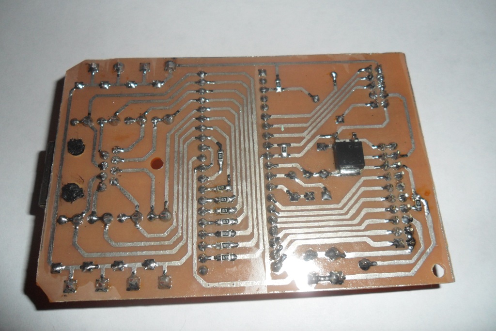
Ready to pay. We drill, solder, wash with alcohol (for whom the hand will rise - with ethyl, personally I washed with isopropyl). After debugging, varnish to protect against corrosion.
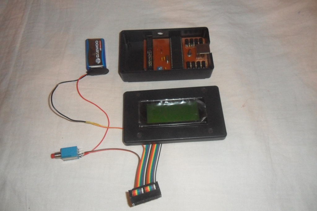
The board is installed in the case , the display is fixed, a loop of jolly colors is soldered to it. The hole for the display cut through the Dremel using a miniature cutting disc, however, there are other methods .
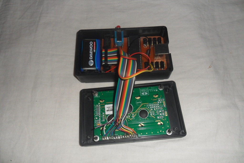
It remains to close the lid.
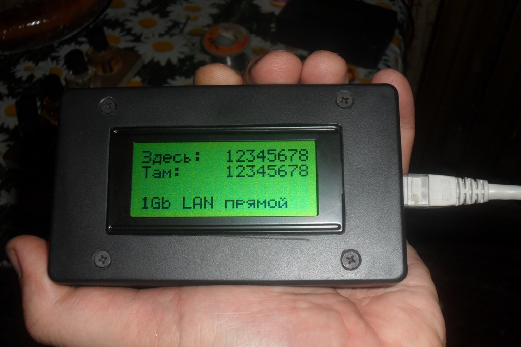
Test: straight factory patch cord, 0.5 m. The power button is located under the index finger on top of the case.
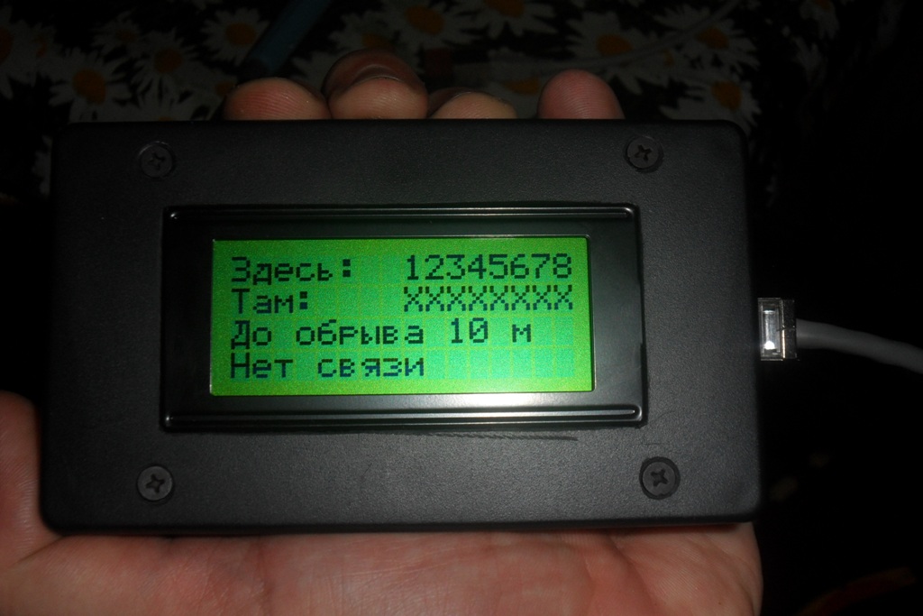
Test: cable length of 10 m, compressed on one side.
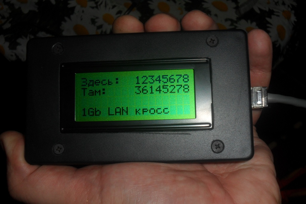
Test: homemade crossover, 10 m.
Upd. At the request of the hackers, I post the source. You can take it here .
But to pay about 800 non-Russian rubles for a device in which I really will use only one function? Dismiss! How does it work, maybe it's easier to do it yourself? Google in hand, and ... sheer disappointment. The search output consists of 80% of the flashing lights with the LEDs on the shift register / AVR / PIC / its own version, and 20% of the profound discussions of forum gurus on the topics “buy% name_cruise_leaning% and don’t worry”. Therefore, I want to offer the habrasoobshchestvu its solution to this problem in the style of DIY. Anyone interested - I ask under the cat (carefully, a certain amount of photos!).
Introductory
Determining the exact cable crimping pattern is necessary.
All information is displayed by the tester. No flashing LEDs on the counterpart. Suppose that the counterpart is in the hands of a monkey, and not even a circus one, and only thanks to the latest technologies did the monkey learn to use a perforator and cross the cable in the sockets. Or, speaking a little more scientifically: the reciprocal part is completely passive.
Hardware
Principle of operation: the counterpart is a set of resistances of various denominations. Let's measure them. Knowing their ratings and decoupling the mating part, we can find out exactly how the cable is crossed. Below is a diagram of the device (all illustrations are clickable). Specific denominations of resistances were chosen rather in view of the presence in the store than consciously, although it turned out to be a piece of the Fibonacci series.
')
Fig. 1. Tester layout
Fig. 2. Scheme mate
The heart of the circuit is an ATMega16 microcontroller. Why precisely he? The dispute "AVR vs PIC" is a typical holivar, so I’ll just say: let arbitrariness be my AVR. And of their entire Mega16 line, the cheapest crystal has an 8-channel ADC on board. I frankly did not want to complicate the circuit with switches of analog signals. An important plus: this model can be bought even in my castle, where in the whole city there is one store of electronic components with prices 150-500% from Moscow.
The microcontroller port A is the ADC inputs, we have an ISP on the port B and a pair of service functions, we use port C to generate test signals, and port D to communicate with the user through an HD44780-compatible display.
We feed the circuit from the “Krona” type battery, through the stabilizer LP2950, DA1 according to the circuit. Why not PWM, and the usual linear stabilizer, even low-dropout? The current consumption is small, on one battery I spent all the testing and debugging of the circuit, I launched a couple of real objects for about fifty ports - until it was discharged. But high-frequency interference, which is a satellite of any PIM, can reduce the accuracy of the ADC. Complicate the scheme, again, I do not want. Why choose LP2950? He was in the store.
Protect the input circuits using suppressors VD1.1 - VD1.8, I took 1,56,8. Of course, they will not save them from getting into 220V, but 60B from any telephone line will be able to repay them.
Chain VD2 - R4 is used to detect the discharge of the battery. On the Zener diode it drops 5.1V. Thus, when the battery voltage drops below 6V, a log will appear on PB2. 0. Here the mind would need a Schmitt trigger, but it was not.
Information output using HD44780-compatible display, I came across WH-1604A-YYH-CT #. Connection diagram is typical and does not require explanation. It should say only about the nominal resistance R5, which sets the brightness of the backlight. The higher the rating, the longer the battery will live - the rest of the circuit consumes less than 5 mA, the main consumer is the display backlight. But if you overdo it, in the dark you will not see anything on the screen. I stopped at 100 ohms.
Software part
For writing the program, I used the AVR Studio 4 environment, the C language. Below I will describe the algorithm of work, but I will not show the code, and there are reasons for that. Firstly, it is somewhat terrible (a picture with a horse, a rainbow vomiting). Secondly, since this is DIY, then the implementation of the algorithms described below is not a sin to write for yourself - but what kind of DIY is this? Well, thirdly, if you don’t want to write, then compiled .hex is present in applications.
Describe the standard procedures such as working with the ADC , the implementation of the exchange with HD44780-compatible display and the like obvious things I do not see the point. Everything has been said long before me.
The work of the tester is divided into several stages, which are repeated cyclically.
Stage 1. Initial checks
- check whether any active equipment is connected to the line. All control lines (port C, recall) translate the state into Hi-Z, measure the voltage on all lines. They should be near zero. Otherwise, we understand that on the other side of the wire anything is connected, but not our counterpart, and it does not make sense to continue further. But it makes sense to inform the user that "there is tension on the line!".
- check the signal level on PB2. If there is 0, then the battery is low. We will report a problem to the user, if everything is OK - we go further.
Stage 2. Check the integrity of the lines and the presence of short circuits
For each of the 8 lines we do the following. We supply + 5V from port C to it, keeping all other lines of the port in a high-impedance state, and measure the voltage on the other lines. If on all lines near zero values - the line under study is broken. If on some of the lines + 5V also appeared, it is a short circuit. Normally, we will see some intermediate values.
Stage 3. Clarification of the scheme of cross
So we got to the most interesting. Having eliminated all the obviously faulty lines (broken and shorted wires), we will start measuring the resistance of the remaining lines (let them be N, 0 <= N <= 8). We introduce the notation:
R xy is the resistance between the x and y lines.
R x is the resistance value connected to line x.
Clearly, R xy = R x + R y
Measuring the resistance between the lines, we get a system of linear equations. Comparing the obtained values of R 1 ... R N with the reference, we find out the scheme of cross.
Resistance is easy to calculate. Let us feed a high level to line X, a low level to line Y, and leave the other lines of port C to Hi-Z. In the circuit (see Fig. 3), the voltage drop on the known resistance formed by the parallel connection of R1.Y and R2.Y according to the scheme is U 1 , and on the unknown R xy falls (U 2 - U 1 ). Therefore, R xy = (R 1 || R 2 ) * (U 2 - U 1 ) / U 1 .
Fig. 3. The principle of measurement of resistance
If N <3 - we are powerless. We can make only one measurement of resistance between them, while we have 2 unknowns - the resistance connected to each of them. A system in which the number of equations is less than the number of unknowns has an infinite set of solutions. We'll have to show the user question marks on these lines — they seem to be working, but it’s not possible to figure out the cross-connect pattern.
With N = 3, we have only one possible option. Measuring all the available resistances R 12 , R 13 , R 23 , we get the system:
R 1 + R 2 = R 12
R 1 + R 3 = R 13
R 2 + R 3 = R 23
It is easy to show that:
R 1 = 1/2 * (R 12 + R 13 - R 23 )
R 2 = R 12 - R 1
R 3 = R 13 - R 1 .
For larger values of N, we can make up a system of equations in a variety of ways, by measuring various resistances R xy . At first glance, there is no difference how to choose which resistances to measure. However, the devil lives in trifles. For example, N = 8, I will explain what I mean. In the first implementation of the algorithm, I did the measurements like this:
R 1 + R 2 = R 12
R 1 + R 3 = R 13
...
R 1 + R 8 = R 18
R 2 + R 3 = R 23
By adding the first two equations and subtracting the last, we get the same 2R 1 = R 12 + R 13 - R 23 , and find all other resistances from equations 1 - 7, where R 1 is already known.
The problem lies in the fact that in some types of cross-connect the value of R 1 turned out to be large (15 kΩ or more), and the error in measuring the resistance with its increase increases. As a result, it turned out that small relative to R 1 resistances with a nominal value of 1-2 kΩ were measured with an error of 70-80%! Obviously, to ensure good accuracy, we should design the system so that in place of R 1 there is another unknown, the lowest of all. To do this, we will have to perform all possible measurements (well, there are not so many of them, at worst 28). In fact, we have an 8 x 8 matrix, symmetric with respect to the main diagonal (it is clear that R xy = R yx ). Choose from all the results of the minimum, let it be R ij = R i + R j . In line i we find R ik , such that R ik > R ij , but less than other elements of the line. We get:
R i + R j = R ij
R i + R k = R ik
R j + R k = R jk
We solve and find the smallest among R i , R j , R k (suppose it turned out to be R i ). the remaining unknowns R x are found from R x = R ix - R i .
Step 4. Determination of the break point, if any
Smart and expensive pieces of iron measure the distance to the point of break with the help of TDR . Difficult, expensive, cool. Our possibilities are much more modest, and it’s not often necessary to know the position of a cliff to centimeters - usually understanding in the style “right next to me”, “at the other end”, “in the middle, where the wall has recently been dug” is more than enough. So - the measurement of cable capacitance.
We translate all the lines of port C, except for the one that is connected in the core where there is a break in Hi-Z. Serve on a + 5V core, charging it. Measure the voltage on it, this will be our initial U 0 . We translate all the lines in Hi-Z. The cable begins to discharge through a resistor R2.X with a resistance of 1 MΩ. After waiting 1 ms, we measure the voltage on this line U.
We must not forget that the circuit on the board, connector, etc. also have their own capacity, so the device needs to be calibrated for a couple of pieces of cable of different lengths. I did it with a zero length of 1710 pF, and the cable capacitance is 35 pF / m. The practice of use showed that even if it is lying, it is not much, by 10 percent. A situation like "where you didn’t finish the contact, in the cabinet on the patch panel or in the outlet? ”is solved instantly.
Total
I use. Satisfied. Those who want to repeat my path can find here an archive with a printed circuit board in DipTrace format, a scheme in sPlan format, firmware MK, and another file with an example command line for avreal, where you can see fuse-bits.
Process photo
Attention! To the author of the article at birth, an artistic feeling was cut out, as a future engineer was not needed. Connoisseurs of the undeveloped horizons, composition of the frame and any other white balance, please stop reading at this place and go directly to the comments, in order to avoid serious emotional trauma.
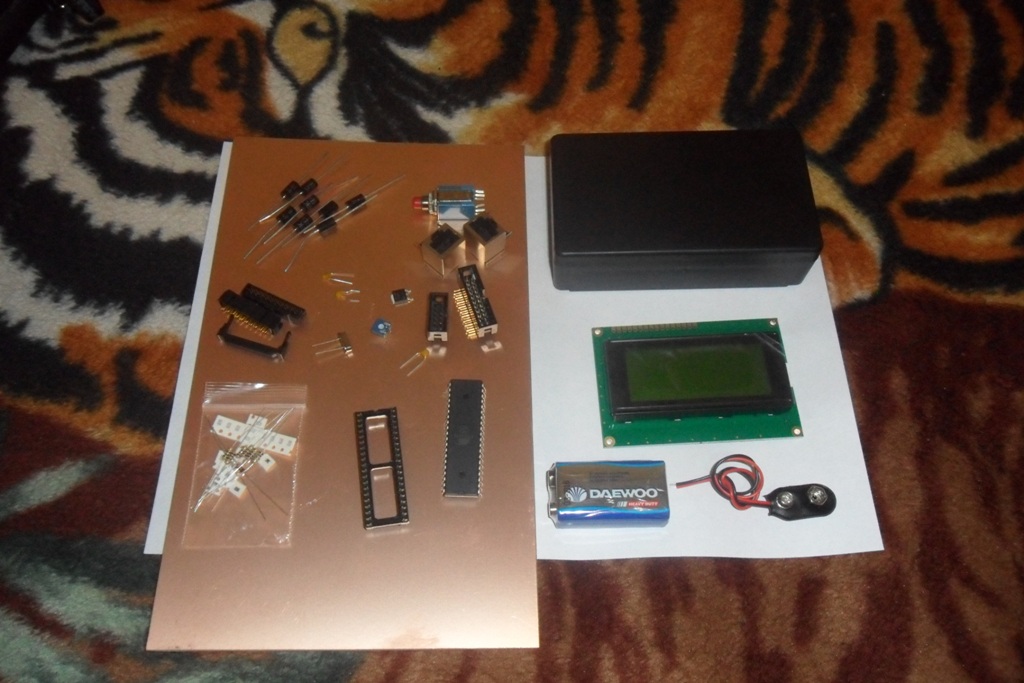
Begin the process.
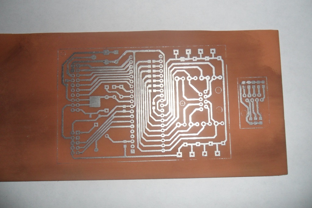
Printed circuit board. Made with the help of LUT , tinning alloy Rose .
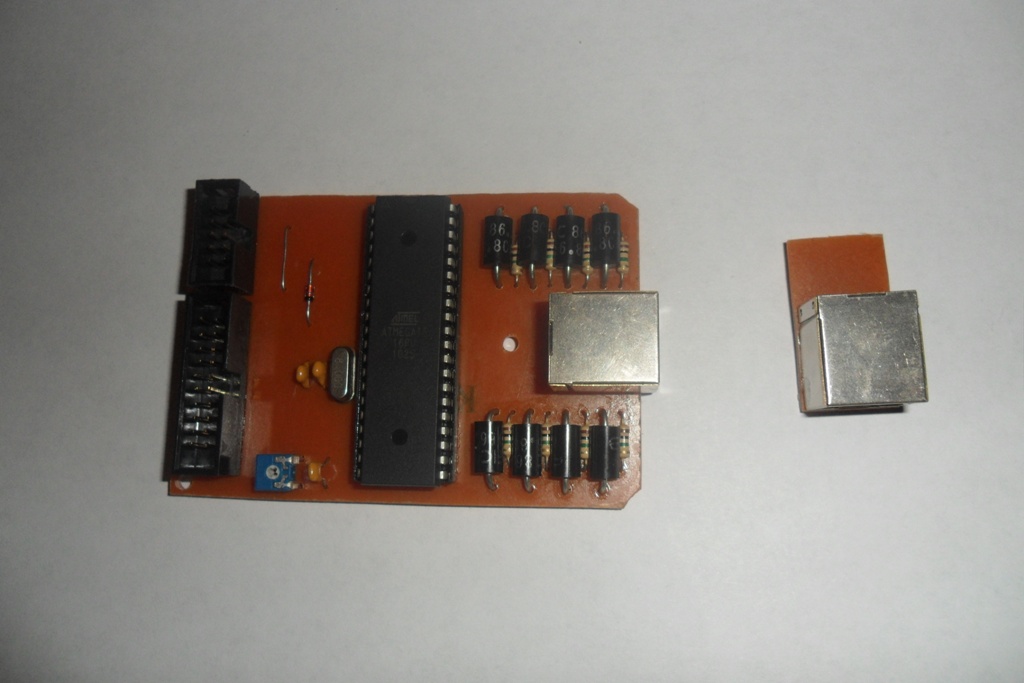
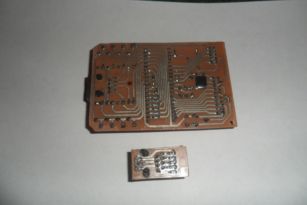
Ready to pay. We drill, solder, wash with alcohol (for whom the hand will rise - with ethyl, personally I washed with isopropyl). After debugging, varnish to protect against corrosion.
The board is installed in the case , the display is fixed, a loop of jolly colors is soldered to it. The hole for the display cut through the Dremel using a miniature cutting disc, however, there are other methods .
It remains to close the lid.
Test: straight factory patch cord, 0.5 m. The power button is located under the index finger on top of the case.
Test: cable length of 10 m, compressed on one side.
Test: homemade crossover, 10 m.
Upd. At the request of the hackers, I post the source. You can take it here .
Source: https://habr.com/ru/post/190632/
All Articles