Acceleration Arduino. Under liquid nitrogen. 20 ⇒ 65.3Mhz @ -196 ° C
 Before the article starts, you should immediately answer 2 questions, don't go to the fortuneteller - they will be asked:
1) What is the practical meaning of this? Understand how electronics behaves at cryogenic temperatures, and it’s just interesting how much AVR can be squeezed out of 20 MHz :-) We managed to figure out a moment that is extremely important for overclocking desktop processors with cryogenic cooling.
2) Why Arduino, because there is a bunch of microcontrollers faster, and i7 in general tears all? Exactly. There are a lot of much more modern microcontrollers, which are 2-3 orders of magnitude faster (and I have them). However, Arduino has received great fame among fans, because it was decided to torment her. And for practical applications, it is certainly cheaper and easier to take faster microcontrollers (Cortex-M3, M4).
')
Overclocking a microcontroller under liquid nitrogen promises to be somewhat more difficult than overclocking “desktop” processors - after all, there are no stability tests, no programmable clock frequency generator, or supply voltage control. And the components on the Arduino, as practice has shown, do not withstand cryogenic temperatures - and they will have to be dealt with individually. Fortunately, all these problems were solved.
A liquid nitrogen
I have long wanted to reach it. It turned out that several companies sell it in Moscow. The closest of all was the scientific research institute KM , where nitrogen is 50 rubles per liter. Some companies are not wincing for 5 liters asking 950 rubles - with them, of course, we are not on the way.Liquid nitrogen is obtained literally from the air — by liquefying it and dividing it on a distillation column, or vice versa — first by releasing the nitrogen from the air with special filters, and then liquefying. As it turned out, even small plants for the production of liquid nitrogen (10 liters per day) are sold. The cost of production for electricity - 5-10 rubles per liter. Now I know exactly what I want for my birthday!
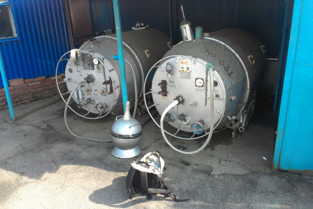
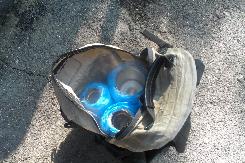
Nitrogen can be transferred in ordinary steel thermos (glass can crack from a sharp drop in temperature). After additional insulation (+1 centimeter of thermal insulation and polyethylene to protect against condensation), nitrogen was boiled away in 30 hours, which is basically enough for work. It is quite expensive to buy a special Dewar vessel, although nitrogen from small (~ 5 liters) “regular” Dewar vessels boils away in 25 days. You also need to remember that in no case can not hermetically close the liquid nitrogen - will tear to shreds.
At physics.stackexchange.com/ it was suggested that thermal insulation should be done the other way around - wear on top, not bottom. To evaporate nitrogen cooled the outer wall of the thermos.

Stress Testing
I had to write a test that tests reading / writing in SRAM, reading from flash, arithmetic operations and program flow test (with branches). The idea of the tests — a sequence of commands was found that takes the system out of the initial state, and then after a certain number of steps — leads to the original one. Download the completed stress test here .Watch tests
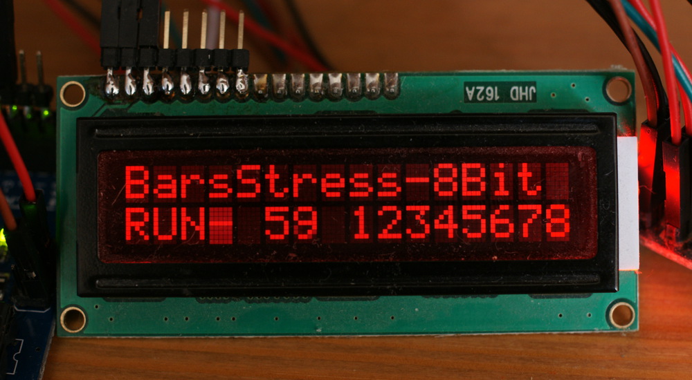
void run_flow_test() { for(int repeat=0;repeat<250;repeat++)//We are aiming at ~10 benches per second { //Program flow check //Magic loop which after 93 itterations yields same value for(unsigned char i=0;i<93;i++) { flow_check=(flow_check<<1) + (flow_check>>7) + 25; if(flow_check&8) flow_check^=4; else flow_check^=16; flow_check=flow_check ^ 192 + 1; } } } void run_mul_test() { for(int repeat=0;repeat<350;repeat++)//We are aiming at ~10 benches per second { //Multiplication check for(unsigned char i=0;i<64;i++) { mul_check=mul_check*(mul_check-1); mul_check=mul_check*(mul_check+1)+2; } } } void run_flash_test() { for(int repeat=0;repeat<1000;repeat++)//We are aiming at ~10 benches per second { //flash_check for(unsigned char i=0;i<16;i++) { flash_check=(flash_check ^ svalue1) + svalue2; flash_check=(flash_check<<((svalue3+flash_check)&7)) + (flash_check>>((svalue3+flash_check)&7)) + svalue4; } } } void run_sram_test() { for(int repeat=0;repeat<10;repeat++)//We are aiming at ~10 benches per second { //SRAM check for(int i=0;i<2405;i++) { value1=(value1+value2+value3+value4+sram_check)&1; value2=(value2+value1+value3+value4+sram_check)&1+1; value3=(value3+value1+value2+value4+sram_check)&1+2; value4=(value4+value1+value2+value3+sram_check)&1+3; sram_check=(sram_check<<1)+(sram_check>>7)+value1+value2+value3+value4; } } } The HD44780 screen connected in a standard way on a 4-bit bus in the second line displays the iteration number of the loop, and 8 hexadecimal digits of the checksums. The first 2 are the SRAM test, then Flash, arithmetic and program flow. If everything is ok, then the checksum should be 12345678. An error in the checksums accumulates. Also, the error code is displayed by blinking of the LED on the board: monotonous blinking is all ok, 1 flash is a SRAM error, 2 is Flash, etc. With tests at ~ -100 ° C - usually found a program flow test error, at -196 ° C - a test with reading / writing SRAM memory.
It was assumed that when the voltage rises, I will have to turn off the display, and rely only on the LED. However, it turned out the opposite - the LED at liquid nitrogen temperature stopped working (due to the expansion of the band gap, the required voltage for ignition was higher than the supply voltage, more on that below).
Clock Generator
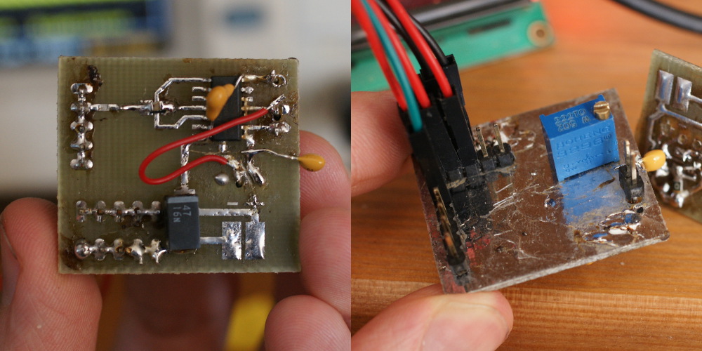
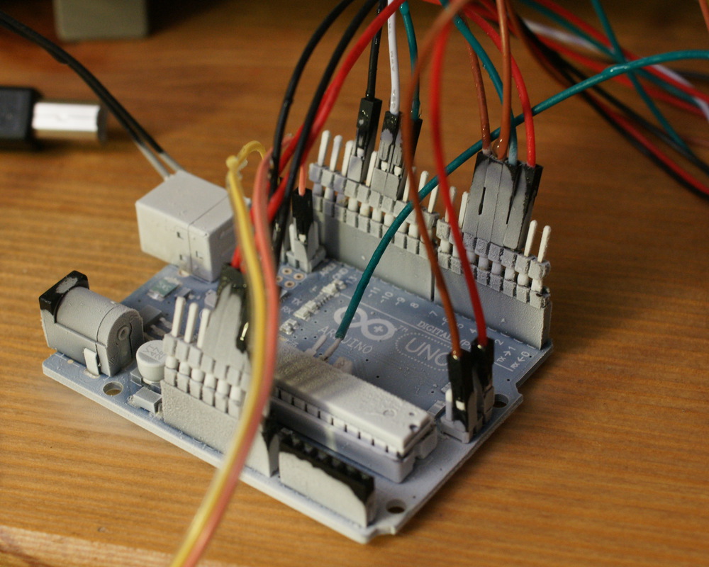
Arduino by default works from quartz. Quartz on the first harmonic usually does not work above 30 MHz, so working with an external generator is inevitable. In order not to solder the Arduin board itself, I turned off 2 legs, to which quartz is connected, and soldered the contact to an external clock frequency. Well, it was necessary to change the fusae for working from an external generator, for which a separate programmer is needed (in my case, the TL866CS MiniPro ). Of course, I thought about this after bending the legs, and the microcontroller had to be installed with crutches in the programmer. In the picture to the left - the Chinese DCDC module on the LM2596 is also visible, with which I changed the supply voltage.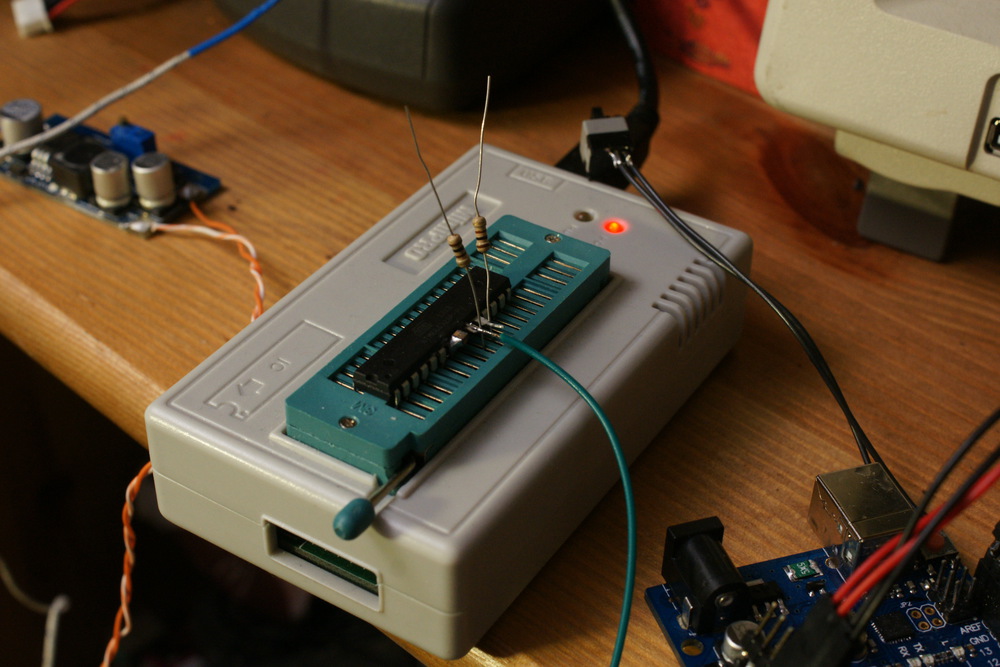
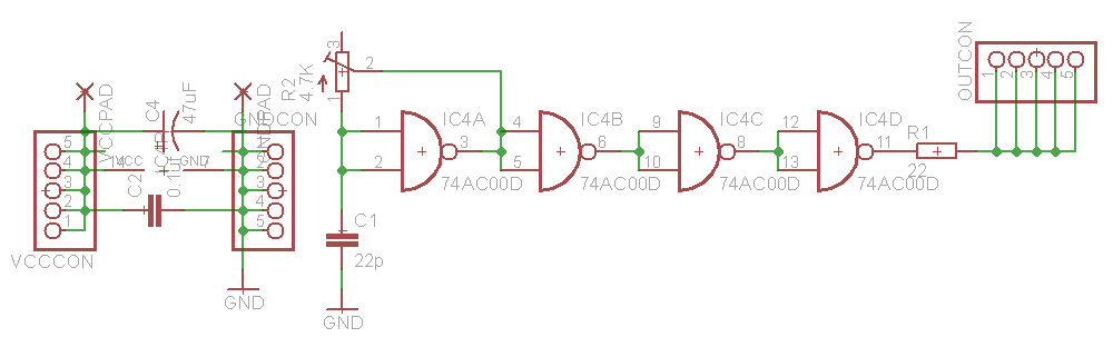
I certainly did not have a signal generator up to 100 MHz - this is not a cheap deal. A tunable generator capable of generating in the required range (16-100 MHz) with a duty cycle of 50% could only be collected from the 4th attempt. It turned out that many generators on logic elements either have a very low maximum frequency or are unstable at high frequencies (some pulses accidentally become shorter / wider). In the end, the following scheme reliably generated over the entire required range. The output resistor R1 is partially sequentially terminated, so that the overshot of the clock signal on the side of the microcontroller is not so scary. We have to work at a higher voltage, so the chip can be burned (with a “sharp” signal with an amplitude of 8V, instantaneous “outliers” on the microcontroller side would be up to 16 volts).
Features of the electronics at cryogenic temperatures
When cooled to -196 degrees, the resistance of metals drops dramatically. For example, for copper - the coil had a resistance of 56.3 ohms at room temperature and only 6.6 ohms when cooled (a drop of 8.5 times).The behavior of capacitors is much more complicated: electrolytic capacitors lose ~ 500,000 times when electrolyte freezes. Ceramic capacitors - depending on the dielectric: the cheapest Y5V - lose almost all capacity when cooled, X7R - lose 66% of capacity and NP0 (C0G) - no more than 1% capacity change (but such capacitors with a capacity of more than 1000 pF are rare). Accordingly, if the decoupling power capacitors were with a Y5V dielectric, then the circuit could lose stability during cooling. You can check the type of dielectric and when heated to 100-150 degrees - the effect on the capacitance is about the same. To eliminate this problem - capacitors with X7R and NP0 insulators were soldered directly onto the microcontroller's power legs.
For semiconductors, the band gap increases, and the electron / hole mobility changes (here the relationship is complex). In practice, this leads to the fact that, for example, silicon diodes - have a voltage drop of not 0.6-0.7 V, but 1.1. This is especially true for analog circuits in which there are many bipolar transistors.
Due to the increase in the width of the forbidden zone - the color of the glow of the LEDs changes, it becomes shorter. This is especially noticeable on orange / yellow LEDs - they turn green. In this case, the required supply voltage greatly increases, and in this case, there was not enough supply voltage to turn it on.
Why chips can start to work faster when cooled? The speed of the CMOS-logic is limited by the speed of charge / discharge of parasitic capacitors (the capacitance of the gate transistors and metal connections). And since when the temperature decreases, the resistance of metals decreases - the speed of work can increase, especially if the circuit has a speed-critical section - these were some kind of long chains.
Those. liquid nitrogen is needed not to remove a large amount of heat (it does this worse than ordinary water with its heat capacity), but to improve the characteristics of the microcircuit by reducing the resistance of internal metal compounds.
Direct overclocking with a dramatic start
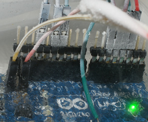
After all these preparations - slowly pour Arduino with liquid nitrogen, I hear the connections crunching there, and suddenly the screen lights go out, and then the board “hangs”. I thought it was the end. Then it turned out that if we slightly raise the board above the nitrogen so that it does not cool so much, the backlight will light up again and the board will work. I hardly managed to overclock it, up to ~ 50 MHz. But of course the result was not reliable, because The temperature of the microcontroller was variable.Suddenly, looking at how the board stops when it is lowered into nitrogen and continues to work when it is warming up, an idea came: what if it comes to protection against too low supply voltage? Disconnected Brown-out detection - and the microcontroller began to work stably when lowering into liquid nitrogen! With the screen, it turned out that the backlight was connected to the 3.3V linear regulator on the board (the power pins were running out) - and as the temperature dropped, it seemed that the protection also worked, the voltage dropped strongly. I connected it directly to 5V - and it also worked.
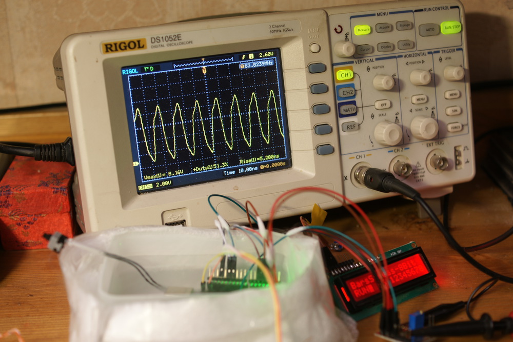
Stable work was about 50 MHz - and I began to increase the voltage. It turned out that above 8 Volt - the system stopped working, and 7.5-8 Volts ensured absolutely stable operation at a frequency of 65.3 MHz. For comparison, at room temperature and 5V - the maximum stable frequency is 32.5 MHz, and at 8V - 37 MHz.
At a frequency of 65 MHz, the test worked stably for more than an hour, for a total of 3 liters of nitrogen was taken for overclocking.
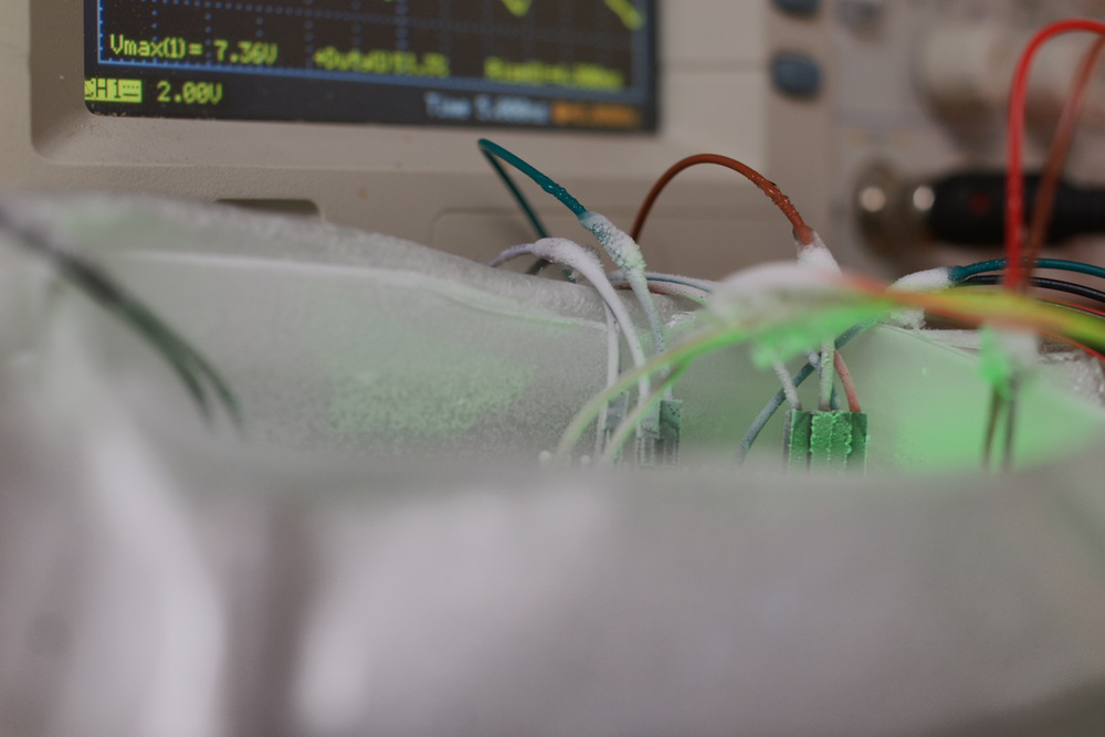
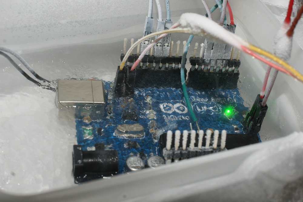
On the air - the board is instantly covered with frost:
In the video, the test at a frequency of 65 MHz begins at 7:12, the type of work of the Arduino under a layer of liquid nitrogen - at 9.00.
And the remains of liquid nitrogen will meet face to face with hot water:
Summary
- Arduino under liquid nitrogen accelerates and runs stably for more than an hour at a frequency of 65.3 MHz, and in air only up to 32.5-37 MHz. The AVR works quietly for a short time at a voltage of 8 volts.
- It was possible to figure out how the parameters of electronic components change during deep cooling: a drop in resistance of metals by ~ 8.5 times, a drop in the capacitance of capacitors (electrolytes, Y5V ceramics - thousands of times, X7R - by 2/3. Capacity NP0 does not change), an increase in the band gap of semiconductors (increase in voltage drop of diodes, change in LED color, very large changes in the operation of analog circuits)
- When overclocking "large" processors - you need to carefully monitor the temperature of the capacitors (electrolytes and cheap ceramic dielectric Y5V). It should not fall below zero - even if for this it is necessary to install additional heating. Otherwise, they will lose almost all capacity, and the processor will lose stability.
- None of the Arduino suffered in the process of writing an article. After warming and drying - continued to work, as before :-)
Ps . From other experiments with liquid nitrogen - phosphorescence of sugar with green light . And if you break the fruit - remove the fragments BEFORE they turned into fruit porridge scattered throughout the room

PS : If anyone knows where to get samples of superconductors - write . What I found is monstrously expensive.
PS : Talk on Reddit
Source: https://habr.com/ru/post/190180/
All Articles