ARMs for the little ones: what time is it?
Today we will deal with two important questions: how to write more efficient code with CMSIS and how to correctly calculate the speed of the processor. We will start with the second part and study the processes that occur in LPC1114 to generate a clock frequency.
Clock frequency - the main source of "labor" in the processor, its generator can be compared with the heart of a person. Different processor components can use different frequencies, which, however, usually arise in the same chip (or resonator).
')
Most processors have a built-in resonator and the ability to connect an external resonator or crystal. Why is this done? Basically, to reduce the cost of the processor. The built-in resonator typically has an error of about 1%, which may be enough for many tasks, but there are even more tasks for which such accuracy is unacceptable. In fact, if we consider, for example, the time on the built-in resonator, the error per day can reach 14 minutes. If you transmit a packet over the network about once every half hour, this is absolutely not a critical error. Another thing, if you make an alarm clock.
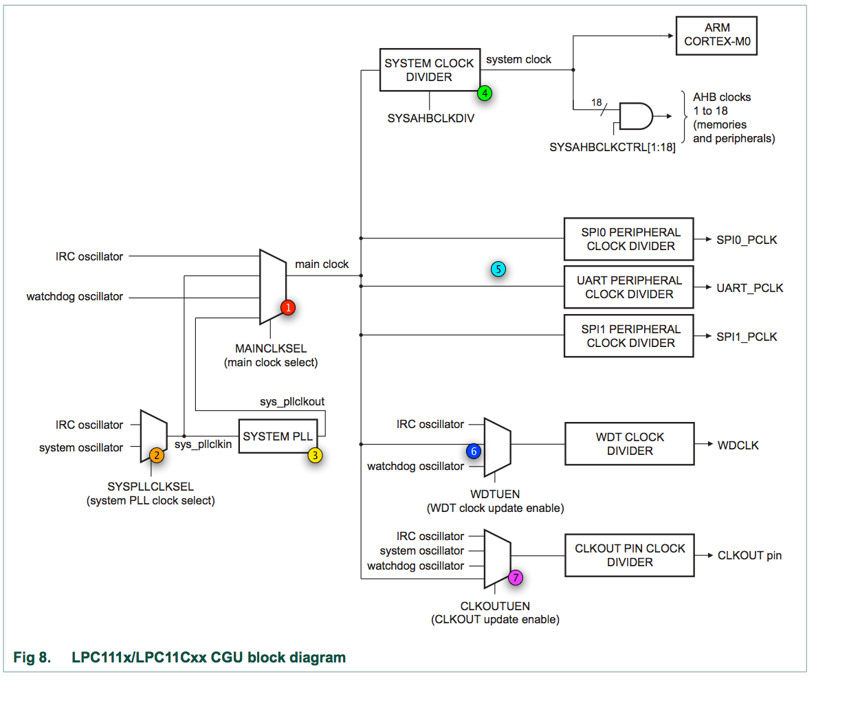
(image from LPC111x User Manual )
Above is an overview of the clock generator, divided into components. Now we will deal with each of them separately.
⓵ Primary frequency
MAINCLKSEL sets the basic frequency on which almost everyone else depends. It can be based on one of several sources.First, it is IRC - internal resonator. The operating frequency is 12 MHz (in fact, it can be tuned in small limits), the error is about 1%. It is from here that the processor clock frequency is generated at the time of launch, so that the entire boot code is executed at a clock frequency of 12 MHz. The variant is as simple as possible (you don’t need to do anything at all so that it works), it does not require additional external components. Unfortunately, it has its own problems: the resonator, as I already mentioned, is somewhat inaccurate, moreover, it is not particularly interesting for us to drive the core at 12 MHz, when it works fine at 50 MHz.
Secondly, the main frequency can be set from another internal generator - watchdog oscillator, which is usually used for watchdog operation. This oscillator operates at speeds (programmatically adjustable) from 9.4 kHz to 2.3 MHz with an error of ± 40% - it would not seem like the best solution for the fundamental frequency. On the other hand, this is exactly the wonderful and energy efficient solution if you need to put the kernel into sleep mode, while leaving some part of the periphery working.
Third, we can get the fundamental frequency from the system oscillator before or after the PLL . We will not now delve into the specifics of the PLL, since this is quite a voluminous topic. I advise those interested to study the section “3.11 System PLL functional description”.
⓶ System Oscillator
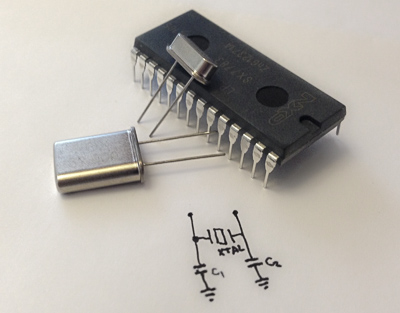
The system oscillator is that part of the processor that will not work without hardware modifications, it lacks the main working force of the oscillator - a crystal (or a quartz resonator) that needs to be connected outside, for which any modern processor has XTALIN / XTALOUT pins.
Specifically, the LPC1114 (however, like the other processors of the LPC111x line) supports crystals with an oscillation frequency from 1 MHz to 25 MHz. In addition to the crystal itself, you will also need two capacitors, the values of which depend on the parameters of the selected crystal. Here I refer you to the datasheet , where in section 12.3 (XTAL input) there is both a wiring diagram and a table with recommended capacitors. In the test circuit, I tried to use a crystal with a frequency of 12 MHz, a load capacity of 20 pF and two 39 pF capacitors, but this mode of operation will not be considered further.
If you have a reliable external clock source, then you can skip the system oscillator, then the clock frequency is taken from the pin XTALIN.
The system oscillator can be used directly as a generator of the main frequency, or it can be previously passed through the PLL.
⓷ PLL
Without going into electrical mechanics, a PLL is a device that multiplies and then divides the input clock frequency. The PLL input can receive the frequency from the IRC or the system oscillator, and the output will be used for the fundamental frequency.
Configuring the PLL parameters is potentially dangerous for the processor internals, because I recommend the NXP-based utility (successfully converted and running to Google Drive) to select the necessary parameters, just set the oscillator frequency at the input and the total frequency you want to receive, and it will calculate the possible options.
The network has an interesting note on how to raise the IRC frequency to generate 50 MHz at the PLL output, but to debug this result, you need an oscilloscope.
⓸ System frequency
Usually, the core (the fact that Cortex-M0) operates at the main frequency, but, if necessary, the main frequency can be divided (up to 255), resulting in a total system frequency. In addition to the core itself, flash memory, RAM and all peripherals will work at this frequency, with the exception of SPI and UART. Keep in mind that the maximum frequency here is 50 MHz.
⓹ And what about SPI and UART?
Due to the specifics of these interfaces, they have their own dedicated frequency dividers, for example, with UART it allows you to select the desired bitrate.
Despite a certain non-obviousness of the circuit, not the main frequency, but the system frequency falls at the input of the divider.
Calculation of the bitrate divider is quite a difficult task, so once again I send you to the instruction - “13.5.15 UART Fractional Divider Register (U0FDR - 0x4000 8028)”. There is both a calculation formula and an explanation for an additional fractional argument, as well as a block diagram for finding the right parameters for a given bit rate and a couple of examples.
In SPI, everything is somehow significantly simpler, most likely because the master on the bus sets the frequency, and the rest of the devices work on it — absentee synchronization is not required. So the only thing we can do is set a divider. The important point is that when the processor is running in master mode, the minimum divider is 2, i.e., at a system frequency of 48 MHz, the data transfer rate on SPI will be 24 MHz.
UPD : as valeriyk correctly noted, this divider is not the only thing that affects the output frequency. For SPI, for example, the carrier frequency is calculated by the formula:
PCLK / (CPSDVSR * (SCR + 1)) , where PCLK is the periphery frequency; CPSDVSR - “predivider”; SCR is the number of prescaler cycles per output bit.⓺ Watchdog on guard of vital activity
Watchdog, by its very nature, is an isolated component. Therefore, a system, IRC or a separate oscillator can be used as the leading frequency. In the same way, watchdog has its own dedicated divider.
Why do you need a separate clock for watchdog? If the program accidentally breaks the main generator, of course! Then she will still have a chance to be reset by the watchdog timer.
⓻ Out
Finally, the processor can generate a clock output on the CLKOUT pin (one of the alternative functions for GPIO 0.1). As the leading frequency, we can use any of the available to us: from oscillators (IRC, system or watchdog) or system frequency (after the PLL, if it is on). And, of course, your divider.
A bit about mbed
We looked at the clock generation process in LPC1114 in detail, but what about LPC1768? In fact, each processor line can be (and most likely it will have its own special approach, so the instructions on this topic should be studied very carefully. The LPC1768 also has an internal oscillator - IRC, but it works at 12 MHz. Besides it has (main) oscillator identical to the system oscillator. On mbed, a 12 MHz crystal is connected to it. Finally, there is a real-time clock (RTC) oscillator, but the crystal is not connected to it.
Also, in addition to the main PLL, there is an additional one that is used to generate a working USB frequency. All peripheral components have independent adjustable dividers with respect to the operating frequency.
Practical nuances of changing frequency
Changing the working clock frequency entails several consequences. The most obvious is the need to reconfigure timers. Also, you will need to reinitialize the peripherals working with protocols where it is important to fix the carrier frequency (UART, USB). Finally, the number of ticks to access flash memory also plays an important role. The default value of LPC1114 is 3 clocks (operating frequency up to 50 MHz, see the FLASHCFG register documentation), which is quite enough for our tasks. But the default value of LPC1768 is 4 clocks, with an operating frequency of up to 80 MHz, which is not enough for us.
However, operating at a higher frequency is likely to be beneficial. Embedded processors spend most of their time in sleep mode, so the faster they work out the wakefulness cycle, the less energy they will spend in the end.
For the work!
Now we have the necessary theoretical baggage, and we are ready to apply this knowledge in practice - to make the LED blink deterministically, 1 time per second.
As you saw earlier, a lot of tasks are performed in the same type - by writing and reading registers (in general, all tasks are performed exactly this way). ARM took care of the fact that tasks that are not tied to a specific processor can be performed by the same C code, for this CMSIS exists - a set of drivers for the processor core. Vendors usually extend it with drivers for the rest of the periphery.
The difficult moment with CMSIS is that sometimes it is not quite clear where to find the current version. The basic set of files can be downloaded directly from ARM , at the time of writing, version 3.01 is available there. In addition to the header files, ARM provides a library for versatile complex calculations on DSP (which is still not in our hardware). The situation is worse with drivers from specific manufacturers. In NXP, for example, CMSIS for LPC1114 is based on CMSIS 1.30, and for LPC1768 - on 2.10. Moreover, in the set of peripheral drivers there are obvious errors in the code. And drivers for TI chips have to be thoroughly searched in Google.
Two important conclusions can be drawn from this: first, the driver code is almost all open, so “trust but verify”: the instruction and datasheet are your main literature on working with peripherals. Secondly, there is almost nothing in the drivers that you couldn’t write yourself, that is, it is a great and often working reference material. The main thing - do not forget to treat it critically, if something looks strange - smoke the instructions on the processor.
The source code is now somewhat more structured. Although as a result it has grown significantly in the number of files, it is now much easier to maintain several different platforms. Sources for today's example are available on GitHub: farcaller / arm-demos (pull requests for new architectures are welcome!).
The source tree is not yet fully combed, in particular, I did not get rid of primitive
boot.s and memmap.ld . The next part will be entirely devoted to the issues of the linker (including garbage collection and proper initialization of .data and .bss), where we will tackle all the controversial issues to the end. The whole code is divided into three categories: app/ contains the “application” files - the actual working code of the example itself. It is decorated in the style of arduino, through the functions setup() and loop() . Platform platform/ stores descriptions of different platforms and platform-specific functions (except platform/common , whose files are linked to all platforms). Finally, in cpu/ are CMSIS for specific processors.This whole harvester is going to be a funny little Rakefile. Probably, it would be possible to get by with make, but I would like to put everything neatly into one file, so you’ll need Ruby no older than version 1.9 to build examples.
Work on the clock
To accomplish our task (remember, we need to flash the LED exactly once a second) we would need some kind of timer. Fortunately, there are several timers in LPC-shny processors, we will work with the most unified - SysTick. This timer is described directly in CMSIS, that is, there is a high probability that it will be in any other processor. It is supposed to be used to measure time slices when switching tasks in the OS, but nothing prevents it from being used for simple tasks.
SysTick is a simple timer that counts down to zero from a given value, where it sets an overflow bit, jerks an interrupt, and starts counting from the beginning.
platform/common/systick.c : void platform_systick_setup(unsigned int load) { SysTick->CTRL = 0x04; SysTick->LOAD = load < 0xffffff ? load : 0xffffff; SysTick->VAL = 0; SysTick->CTRL = 0x05; } To begin with about syntax. These wonderful structures are accessible to us from CMSIS, it is no longer necessary to remember where the registers are located, and access to the fields is realized much more clearly.
To initialize the timer, we write 4 to the control register. This turns off the timer, if it was turned on, turns off the interrupt, and sets SysTick to use the processor frequency (remember, the default is 12 MHz). Next, we load the starting point of reference into the SYST_RVR register, limiting the maximum to 16777215, reset the current register value to zero and start the timer.
Now, how do we wait one second:
void platform_systick_wait() { volatile int i; i = SysTick->CTRL; while((i & 0x00010000) == 0) { i = SysTick->CTRL; } } We read the COUNTFLAG value from the SYST_CSR register. COUNTFLAG is set to one when the counter goes to a new circle, and is reset to zero when reading. Thus, we will be in a loop until the counter overflows.
Let's look in other files of our project.
app/systick-blink.c : #include "platform.h" void setup() { platform_led_setup(); #if PLATFORM == MBED platform_systick_setup(4000000); #elif PLATFORM == PROTOBOARD platform_systick_setup(12000000); #else #error Unknown platform #endif } void loop() { platform_led_toggle(1); platform_systick_wait(); platform_led_toggle(0); platform_systick_wait(); } It's all quite clear. Initialize the “driver” of the LED and the timer, and in the cycle we turn on / off the LED with a delay. Depending on the platform, we use a different start value for the timer (IRC on mbed and protoboard work for us at different frequencies). And how does the code of the LED itself?
platform/protoboard/led.c : #include "LPC11xx.h" #define LED_PIN (1<<9) void platform_led_setup() { LPC_GPIO1->DIR |= LED_PIN; } void platform_led_toggle(int on) { LPC_GPIO1->MASKED_ACCESS[LED_PIN] = on ? LED_PIN : 0; } As you can see, with CMSIS everything became really more readable. The only interesting point is that instead of the general register of the GPIO, we now use a register with a mask. It allows you to set GPIO bits for specific pins with a mask, i.e., you can simply write the desired value without thinking about maintaining the state of neighboring pins. More details (and in pictures) about this can be found in the instructions: "12.4.1 Write / read data operation".
For comparison, here is the code for mbed.
platform/mbed/led.c : #include "LPC17xx.h" #define LED_PIN (1<<18) #define LED_PIN_IN_B2 (1<<2) void platform_led_setup() { LPC_GPIO1->FIODIR |= LED_PIN; } void platform_led_toggle(int on) { LPC_GPIO1->FIOMASK2 |= ~LED_PIN_IN_B2; if (on) { LPC_GPIO1->FIOSET2 = LED_PIN_IN_B2; } else { LPC_GPIO1->FIOCLR2 = LED_PIN_IN_B2; } } As you can see, it is very similar. LPC1768 does not have the ability to set the mask directly in the pointer address, but there is a byte access to the registers, which generates a slightly more efficient assembler listing.
You can
rake build_protoboard project with the rake build_protoboard or rake build_mbed . You can even immediately flash the device: rake upload_protoboard TTY=/dev/ftdi/tty/device or rake upload_mbed MOUNT=/Volumes/MBED respectively. Now the LEDs blink identically on both devices.Play frequency?
It seems that we have decided the task - the LED flashes at the correct interval, but something else remains behind the scenes. The maximum operating frequency of the LPC1114 is 50 MHz, and the LPC1768 has even more - 100 MHz, it turns out that we are driving them hardly a third of the power!
It is time to do the correct platform initialization.
platform/protoboard/init.c : #define CLOCK_MODE_IRC 0 // 12 MHz #define CLOCK_MODE_IRC_WITH_PLL 1 // 48 MHz #define CLOCK_MODE_SYS_WITH_PLL 2 // 48 MHz with external 12MHz crystal #define CLOCK_MODE CLOCK_MODE_IRC Three LPC1114 templates are available in the source code: standard 12 MHz from IRC, 48 MHz from IRC passed through the PLL, and 48 MHz from the system oscillator passed through the PLL. The latter option requires additional hardware support, but we are considering it, since this is a very relevant mode of use.
void platform_init() { // set up system oscillator and toggle PLL to point at it #if CLOCK_MODE == CLOCK_MODE_SYS_WITH_PLL int i; // power up system oscillator LPC_SYSCON->PDRUNCFG &= ~(1 << 5); // oscillator is not bypassed, runs at 1-20MHz range LPC_SYSCON->SYSOSCCTRL = 0; // allow circutry to settle down for (i = 0; i < 200; ++i) __NOP(); // set PLL clock source to system oscillator LPC_SYSCON->SYSPLLCLKSEL = 1; // wait for PLL clock source to be updated LPC_SYSCON->SYSPLLCLKUEN = 1; LPC_SYSCON->SYSPLLCLKUEN = 0; LPC_SYSCON->SYSPLLCLKUEN = 1; while (!(LPC_SYSCON->SYSPLLCLKUEN & 1)) ; #endif If we work from the system oscillator, it must be correctly initialized, and first of all - to include. As we discussed earlier, the oscillator can be skipped if an already generated clock signal is present at the XTALIN input.
After the initial initialization, a small delay should be made. Next, we transfer the PLL to work from the system oscillator (instead of IRC), for this there is an interesting mechanism: we write 0, we write 1, we wait - the register will start to return 1.
// set up PLL if it's used #if CLOCK_MODE == CLOCK_MODE_IRC_WITH_PLL || CLOCK_MODE == CLOCK_MODE_SYS_WITH_PLL // set up PLL dividers LPC_SYSCON->SYSPLLCTRL = 0x23; // M = 3, P = 12MHz // PLLout = 12MHz * (M+1) / P = 48MHz // power up PLL LPC_SYSCON->PDRUNCFG &= ~(1 << 7); // wait until PLL is locked while (!(LPC_SYSCON->SYSPLLSTAT & 1)) ; // switch main clock to be driven from PLL LPC_SYSCON->MAINCLKSEL = 3; // wait for main clock source to be updated LPC_SYSCON->MAINCLKUEN = 1; LPC_SYSCON->MAINCLKUEN = 0; LPC_SYSCON->MAINCLKUEN = 1; while (!(LPC_SYSCON->MAINCLKUEN & 1)) ; #endif The second part initializes the PLL, which at this stage receives a signal from either the IRC or the system oscillator at the input. We adjust the dividers according to the formula from the instruction, turn on the PLL and wait until it is blocked. The main frequency after loading works from IRC, we transfer it to work from the output of the PLL and wait until this change is “fixed”.
At 48 MHz for SysTick we need 48000000 cycles, but this is more than its maximum value. One solution is to wait for several timer cycles, which is implemented in the
platform_systick_wait_loop function (another option would be to use the 32-bit CT32B0 timer).LPC1768 code, again, is generally similar. The important point here is that the output from the PLL should be at least 275 MHz, when the input to the processor is no more than 100 MHz. In general, we carefully check the dividers. It is also important to note that we increase the number of ticks needed to access flash memory, because we will work at a frequency that deducts than the default value.
platform/mbed/init.c : // if we go for clock > 80 MHz, we need to set up flash access time LPC_SC->FLASHCFG = (LPC_SC->FLASHCFG & 0xFFF) | 0x4000; // 4 cpu clocks The code shown in the example is relevant only for LPC1768 on mbed, since it is tied to a specific frequency of the crystal. Moreover, if you are working with LPC1768 "directly", then its bootloader starts with IRC with the PLL turned on , so you need to turn it off in its initializer.
Summing up
I also wanted to tell you today about CLKOUT and how you can control the frequency with a logic analyzer or an oscilloscope, but the article would be too big. CLKOUT, 32-bit timers, interrupts, and sleep modes — all of this will be in future releases.
I was reached by a box with Stellaris LaunchPad, I’ll think about how best it would be to add another architecture without inflating the story. , LPC1114 , .
«», .
PS , pfactum . , :-).
 This work is available under the Creative Commons Attribution-NonCommercial-NoDerivs 3.0 Unported license . The program text of the examples is available under the Unlicense license (unless otherwise indicated in the headers of the files). .
Source: https://habr.com/ru/post/190032/
All Articles