Tricky network issues
It has long been the idea to put together interesting questions about networks.
What unites them is that they are all fairly simple, but sometimes we don’t think about them (I didn’t think about them anyway).
In general, I collected them, knocked them out, and found the answers.
So, blitz poll:
')
According to the 802.3 standard, we have:
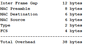
Why, when calculating overhead, Ethernet overhead is taken as 14 bytes, not 38 or 18 (Dest + Source + Legth + FCS).
On the other hand, Ethernet II is now generally accepted.
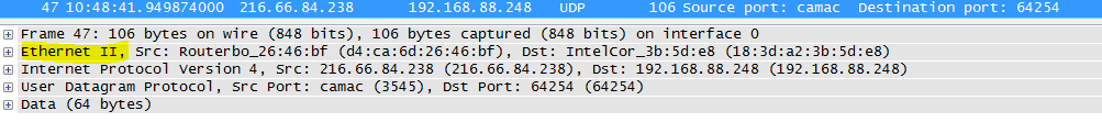
What is the difference between Ethernet II frames and 802.3 frames and why is it even II?
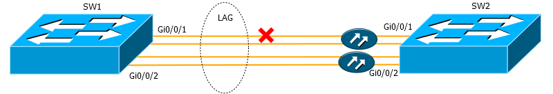
Here the switches are connected by two optical interfaces integrated into the LAG. Two optical cables are used as the medium - one for reception and the other for transmission. What happens after a single cable breaks?
And why such a ping does not work:

1. te2-4 PAO2 bl (69 22 1 3 209) 1 160 1 060 1 029 4.ar5.PAO2.gblx.net (69.22.153.209) 1.160 ms 1.060 ms 1.029 ms
2. 192.205.34.245 (192.205.34.245) 3.984 ms 3.810 ms 3.786 ms
3. tbr1 sffca ip att net (12 123 12 25) 74 848 ms 74 859 ms 74 936 ms tbr1.sffca.ip.att.net (12.123.12.25) 74.848 ms 74.859 ms 74.936 ms
4. cr1.sffca.ip.att.net (12.122.19.1) 74.344 ms 74.612 ms 74.072 ms
5. cr1.cgp ( ) cil.ip.att.net (12.122.4.122) 74.827 ms 75.061 ms 74.640 ms
6. cr2.cgcil.ip.att.net (12.122.2.54) 75.279 ms 74.839 ms 75.238 ms
7. cr1.n54ny.ip.att.net (12.122.1.1) 74.667 ms 74.501 ms 77.266 ms
8. gbr7.n54ny.ip.att.net (12.122.4.133) 74.443 ms 74.357 ms 75.397 ms
9. ar3.n54ny.ip.att.net (12.123.0.77) 74.648 ms 74.369 ms 74.415 ms
10.12 126 0 29 (12 126 0 29) 76 104 76 283 76 174 12.126.0.29 (12.126.0.29) 76.104 ms 76.283 ms 76.174 ms
11.route-server.cbbtier3.att.net (12.0.1.28) 74.360 ms 74.303 ms 74.272 ms


1597 ) .
:
, , , . , , .
? ?
— . , ? 192.168.1.110/24 , 192.168.1.0/24. .
— . , , . .
, , ?
, , , , .
:
? .
UPD :
.
What unites them is that they are all fairly simple, but sometimes we don’t think about them (I didn’t think about them anyway).
In general, I collected them, knocked them out, and found the answers.
So, blitz poll:
Let's start with the lowest levels and the simplest questions.
')
IN 1. Why is such a strange order chosen for the twisted pair: the blue pair by 4-5, breaking the green one, which is 3, 6?
Answer
O1 : This is done for the sake of a two-pin telephone connector. Thus, for example, both a telephone cable and a twisted pair cable can be inserted into the patch panel.
It is possible even to bring the network and telephony through one cable, but I did not tell you that!
habrahabr.ru/post/158177 .
It is possible even to bring the network and telephony through one cable, but I did not tell you that!
habrahabr.ru/post/158177 .
AT 2. In the Ethernet standard, there is always a gap between frames called the IFG (Inter Frame Gap) that is 12 bytes long. What is it for, and why is it present in modern standards?
Answer
O2 : IFG was used extensively in the heyday of CSMA / CD. This is a pause that the sending device must make before sending the frame to avoid collisions.
The fact is that when several hosts are connected to the hub, there is a high probability that they will start sending data at one time, and a collision will occur or one station will occupy the monopoly channel.
When using IFG while one host is waiting, the other can send.
Generally speaking, IFG is measured in microseconds. Its duration for Fast Ethernet is 0.96 microseconds.
Already in gigabit CSMA / CD is only conditionally, but in 10G it is not at all. This is because the collision domain of modern switches is limited to a single interface / cable, plus they work in full duplex mode.
So why are we still losing the precious 12 bytes?
Just no one wants to change the standard.
Colorful description Search by words "Now what is not shown"
IN 3. What caused the limit on the length of the Ethernet segment and the minimum frame size?
Answer
O3 : Usually this fact is explained by the fact that attenuation and
The true reason lies in the same CSMA / CD mechanism.
In order for a line collision to be successfully detected, at the moment when the first bit is received on the remote side, the station must not yet finish transmitting the current portion of data.
I will explain on the fingers. We take a half-duplex network. Suppose station 1 starts transmitting data. Behind her, station 2 is trying to transmit something. It has not yet received a signal from Station 1 and therefore it can. The signal from station 2 will reach station 1 before it finishes transmitting its data. Both stations detect a collision and stop the transmission. All perfectly. The data is not lost and the next time they will definitely succeed.
Now suppose another situation. Station 1 transmitted a portion of the data and is preparing for the next one. But the signal has not reached station 2 yet, she understands that it is possible to transmit.
Yeah, somewhere in the middle they crossed. Station 2 understood this and stopped the transmission, and Station 1 received the corrupted data, while continuing to think that it had fulfilled its signal transmission task, and therefore undertakes the next batch.
As a result, the frame was lost, because they failed to collect it on the back side - they did not receive everything. Yes, higher protocols can detect this, re-request them again, but how many vain milliseconds will be spent for this?
This situation is excluded if the condition stated at the beginning is fulfilled: when the first bit at the end of the segment is received, the sender has not yet transmitted the last bit. Then nothing will be lost.
But back to the length of the segment. You probably already started to guess what the salt? The length must be such that this condition is satisfied.
So, discarding tricky ways of counting, 100 m is exactly the distance at which the distant side has not yet sent the last sending when receiving the first bit.
It remains to determine the size of this data block.
The minimum portion of data for the Fast Ethernet standard is 512 bits or 64 bytes - this is the so-called Slot time. Nothing this figure resembles? The minimum size of an Ethernet frame, perhaps? (For Gigabit Ethernet, this value is increased to 512 bytes).
Exactly these 64 bytes and should stretch the entire length of the segment.
I tried to understand this topic in more detail and prepared a separate material to make it easier for you to understand: 100 meters of Ethernet .
www.ixbt.com/comm/tech-fast-ethernet.shtml#_Toc91050385
AT 4. How Ethernet Overhead is Computed
According to the 802.3 standard, we have:
Why, when calculating overhead, Ethernet overhead is taken as 14 bytes, not 38 or 18 (Dest + Source + Legth + FCS).
Answer
4 : It is easy to understand why the Preamble and the IFG do not count. As you know, Ethernet combines the functions of the link and the physical layer of the OSI model. And while MAC DST, MAC SRC, Type, and FCS are the data link layer attributes, the preamble and the IFG are physical. It is logical that when processing a frame, the device focuses only on its useful length, without overhead bytes of the physical layer.
At the same time note that when calculating bandwidth capacity, the full length is still taken into account: 38 bytes + payload.
Good, but what about FCS? After all, it is most often not taken into account when calculating overhead costs (overhead) and only 14 bytes are added to the length of the payload (MAC DST + MAC SRC + Type).
Here the devil is in the details and to find the answer, you need to turn to the very essence of FCS - Frame Check Sequence. IP does not have built-in controls for the integrity of the source information, so these functions are assumed by TCP (general control - whether all data is delivered correctly) and Ethernet. The latter checks for damage every particular frame, calculate the checksum. That is, it takes the entire frame with the exception of the FCS field, processes it and compares the result with the original value of the checksum, if not the same, discards it. If it matches, the FCS field is cleared first, then the remaining frame is transmitted to higher authorities. In fact, this processing takes place in the gland at an early stage, and those processes that deal with the actual frame and calculate its size actually receive only 14 redundant bytes of the header.
Such an interesting arithmetic.
forum.nil.com/viewtopic.php?f=12&p=582
AT 5. Did you know that the real bit rate of fast ethernet is 125 Mb / s? Why is that?
Answer
O5 : Ethernet borrows from FDDI the 4B / 5B encoding method, when any four bits of the MAC sublayer are represented by five physical bits with alternating zeros and ones. For what it is done - already deep physics.
In this case, the source data should be transmitted at a speed of 100 Mb / s according to the Ethernet standard. Because of this excess bit, the actual speed is 25% more (5 more than 4 to 25%), which is, of course, 125 MB / s.
citforum.ru/nets/lvs/glava_5.shtml
In this case, the source data should be transmitted at a speed of 100 Mb / s according to the Ethernet standard. Because of this excess bit, the actual speed is 25% more (5 more than 4 to 25%), which is, of course, 125 MB / s.
citforum.ru/nets/lvs/glava_5.shtml
AT 6. Everyone knows that the 802 committee deals with LAN standards. Also, it is well known that Ethernet is 802.3
On the other hand, Ethernet II is now generally accepted.
What is the difference between Ethernet II frames and 802.3 frames and why is it even II?
Answer
O6 : 802.3 frames contain the Length field instead of the Type (EtherType) we are used to. Historically, there are several standards for Ethernet frames (besides those listed).
Then DEC, Intel and Xerox refined them to a universal, beautiful Ethernet II solution (Ethernet DIX by the first letters of the companies), which has become extremely popular - IP works on top of it.
The Length field has previously spoken about the total size of the payload, which was generally not very informative, and all the more such a frame could carry only one type of higher protocol. Length values can be up to 1500 (0x05dc).
In the Ethernet II frame, the Length field was abandoned and the rest 2 bytes were used under the Type (EtherType) field, which defines the type of the upstream protocol. To clearly distinguish them from 802.3, values above 1536 (0x0600) are taken.
For example, if the frame carries IPv4, the type will be 0x0800, ARP - 0x0806, VLAN (802.1q) - 0x8100, IPv6 - 0x86DD, QinQ - 0x9100, etc.
pascal.tsu.ru/other/frames.html#as-h4-2325214
We rise a little higher
AT 7. LACP is used to manage interfaces in the LAG. Can he track this situation
Here the switches are connected by two optical interfaces integrated into the LAG. Two optical cables are used as the medium - one for reception and the other for transmission. What happens after a single cable breaks?
Answer
A7 : Generally speaking LACP is the most efficient protocol. It decides whether to add or remove an interface from the LAG almost exclusively on the basis of what state the interface has - Up or Down.
If only one cable is broken, transmission in one direction will stop - the laser signal will disappear. As a rule, the switch, as soon as it stops seeing the signal from the remote side, switches the interface to the Down state. In the situation as in the figure, the SW2 signal stops seeing, because the cable is damaged, and translates the Gi0 / 0/1 interface into Down. At the same time, the SW1 signal also sees its Gi0 / 0/1 interface in Up.
On SW2, LACP removes Gi0 / 0/1 from the LAG, but not on SW1. Thus, there is a problem with data transfer.
To avoid such situations, you must use one of the UDLD (UniDirectional Link Detection) protocols, such as BFD or EFM OAM.
UPD: User Karroplan amended this question:
LACP perfectly identifies unidirectional links. Timeout is either 1 or 30 seconds - there are two mechanisms in lacp, fast and slow transmission.
UDLD / BFD is needed only to reduce the reaction time. Moreover, at one time I had to issue a separate RFC for BFD over LACP, since BFD is initially L3 protocol and perceives the entire PortChannel as one aggregated link and can determine only the fall of the entire link.
More higher
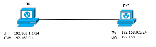
AT 8. Can ping each other two computers in such conditions
Answer
O8 : Yes, they can. Although the default gateway is on a different subnet, ARP requests will be sent in search of it.
That is, PC1 sends a broadcast ARP request, "Who is there 192.168.0.1?". PC2 gets it and, of course, replies that this is it. PC1 receives the ARP reply and inserts its MAC address and IP address into its table. Further, nothing prevents them from sharing data.
UPD: The user merlin-vrn gave a more accurate, comprehensive answer to this question:
The bottom line is that before adding such a route by default (not on the same subnet), you need to have a route to it in the routing table, which, of course, is not there initially. But Windows hidden adds it, so ping works.
That is, PC1 sends a broadcast ARP request, "Who is there 192.168.0.1?". PC2 gets it and, of course, replies that this is it. PC1 receives the ARP reply and inserts its MAC address and IP address into its table. Further, nothing prevents them from sharing data.
UPD: The user merlin-vrn gave a more accurate, comprehensive answer to this question:
How should PC1 get to 192.168.0.1?
1. We look, whether not the local address it. No, not local.
2. We look, whether there is no it in any of local area networks (here 192.168.1.0/24). No, it is not.
3. We are looking for a gateway and make an ARP request to it. And through which interface? Op-pa. Where to look for 192.168.0.1? We do not know.
You will say that "once the network card in the settings indicated 1, then through it and look for." Good. This is equivalent to the route “192.168.0.1/32 via network card1”, which, in fact, Windows will do.
Those. the configuration given in the example is actually arranged as follows:
PC1: 192.168.1.1/32, 192.168.0.1/32 via e0,
PC2: 192.168.0.1/32, 192.168.1.1/32 via e0.
Those. we have two computers and local routes “directly” to each other, even though it is on different subnets. Of course, will ping.
The bottom line is that before adding such a route by default (not on the same subnet), you need to have a route to it in the routing table, which, of course, is not there initially. But Windows hidden adds it, so ping works.
AT 9. What is the difference between Directed Broadcast (192.168.0.255) and Limited broadcast (255.255.255.255)
Answer
A9 : The packet sent to 255.255.255.255 is limited only by the network where it originated - the MAC address is set in ffff-ffff-ffff. If the packet is sent to 192.168.0.255, then first, according to all the routing rules, the packet reaches the destination network 192.168.0.0, and only then it is sent to all the hosts on this network.
Q10: Can the address 10.0.1.0 be used for the host address?
Answer
A10 : Yes, of course, it can, if for example, on the interface you have a configuration of 10.0.0.0/23. Then the range of available addresses will be 10.0.0.1-10.0.1.254 and all of them can be used. Including 10.0.0.255.
UPD: The second example is the use of the / 31 mask, when the network address and the broadcast address can be assigned to nodes.
UPD: The second example is the use of the / 31 mask, when the network address and the broadcast address can be assigned to nodes.
AT 11. What is fundamentally different from the usual reverse mask?
Answer
O11 : Naturally, a noticeable difference in the inversion of this mask, that is, zeros denotes the part that should be unchanged. But it does not matter in principle.
The significant difference is that here zeros can alternate with ones. That is, if the subnet mask cannot contain such a set: 10110001, then the reverse mask can.
Thus, for example, you can select hosts with the address 10.5..123 in all subnets, for example, and allow them access to the Internet. Or separate all even and odd even addresses and implement traffic distribution exactly in half based on the sender's address.
UPD: The difference also lies in the fact that the direct mask operates with networks, and the reverse - with hosts.
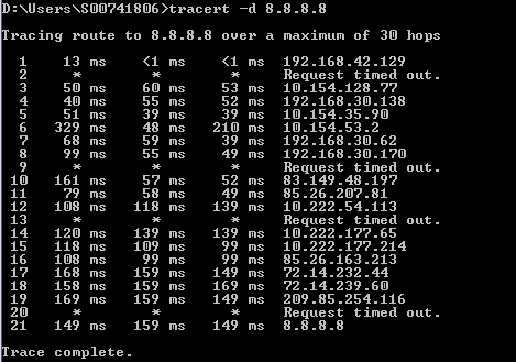
AT 12. What are the addresses for 169.254.0.0/16 (auto-tuning APIPA in Windows and nonzeroconf in unix)
And why such a ping does not work:
Answer
A12 : Network 169.254.0.0/16 was originally conceived as a Link-Local network.
Its essence lies in the fact that if the host does not have a static IP address and cannot receive it automatically, for example, from a DHCP server, then it itself assigns an address from the range 169.254.0.1-169.254.255.254. After that, he will be able to communicate with other hosts on this network that have the same addresses.
The address is chosen randomly due to the random number generator so that it does not match the already existing address (checked by ARP request).
An example of an application would be some kind of Ad-Hoc network, where stations have a task to communicate with each other.
But the key feature of such a network is that relationships are possible only between stations located in this segment, hence the Link-local phrase in the definition. Packets cannot be forwarded on the router. Moreover, even if the gateway’s address is specified by the hosts, according to the standard, it should not send packets to it under any circumstances.
This explains the fact that ping, as in the picture does not work. All according to RFC .
B13. Do you know how many addresses disappear except for the well-known private and 127/8 addresses?
Answer
O13 : In fact, we lose:
One class A network: 127.0.0.0/8
Single Class B Network: 169.254.0.0/16
One network / 10: 100.64.0.0/10
One network / 15: 198.18.0.0/15
Five networks of class C: 192.0.0.0/24, 192.0.2.0/24, 192.88.99.0/24, 198.51.100.0/24, 203.0.113.0/24.
And one network / 4: 240.0.0.0/4
Total 285410560 addresses.
Here we are wasteful .
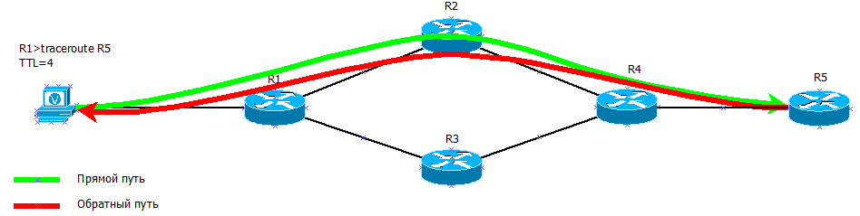
Why during the trace there can be such situations
B14 On one of the hops for all three tracing results, the delay is higher than the next
[eucariot]$ traceroute 8.8.8.8
traceroute to 8.8.8.8 (8.8.8.8), 30 hops max, 40 byte packets
...
6 vl545.mag02.lon01.atlas.cogentco.com (149.6.3.153) 11.464 ms 11.378 ms 11.347 ms
7 te0-7-0-5.ccr21.lon01.atlas.cogentco.com (154.54.74.109) 5.653 ms 4.725 ms 6.209 ms
8 te3-2.ccr01.lon18.atlas.cogentco.com (154.54.62.66) 4.951 ms te2-1.ccr01.lon18.atlas.cogentco.com (154.54.61.214) 5.050 ms te3-2.ccr01.lon18.atlas.cogentco.com (154.54.62.66) 5.086 ms
14: , , , /. , .
UPD: JDima :
, . , 3 , , , 2. ?
, . . , , .
, , — Round Trip Timer, .
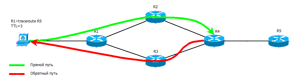
TTL=3 R4 , . R3 — 26- , 90 /. .
, traceroute TTL=4 .
UPD: JDima :
:
time exceeded , .
:
Cat6500. «» (, , , ssh ..) MSFC. MSFC PFC ( DFC ), . , MSFC.
TTL 0 PFC, , , ( time exceeded ( MPLS, )). MSFC. , ICMP , , .
, . , 3 , , , 2. ?
, . . , , .
, , — Round Trip Timer, .
TTL=3 R4 , . R3 — 26- , 90 /. .
, traceroute TTL=4 .
15. ( ). , ?
15: RFC , AS.
, - , , . , TTL expired , traceroute.
, .

.
, - , , . , TTL expired , traceroute.
, .
.
16. ?
1. te2-4 PAO2 bl (69 22 1 3 209) 1 160 1 060 1 029 4.ar5.PAO2.gblx.net (69.22.153.209) 1.160 ms 1.060 ms 1.029 ms
2. 192.205.34.245 (192.205.34.245) 3.984 ms 3.810 ms 3.786 ms
3. tbr1 sffca ip att net (12 123 12 25) 74 848 ms 74 859 ms 74 936 ms tbr1.sffca.ip.att.net (12.123.12.25) 74.848 ms 74.859 ms 74.936 ms
4. cr1.sffca.ip.att.net (12.122.19.1) 74.344 ms 74.612 ms 74.072 ms
5. cr1.cgp ( ) cil.ip.att.net (12.122.4.122) 74.827 ms 75.061 ms 74.640 ms
6. cr2.cgcil.ip.att.net (12.122.2.54) 75.279 ms 74.839 ms 75.238 ms
7. cr1.n54ny.ip.att.net (12.122.1.1) 74.667 ms 74.501 ms 77.266 ms
8. gbr7.n54ny.ip.att.net (12.122.4.133) 74.443 ms 74.357 ms 75.397 ms
9. ar3.n54ny.ip.att.net (12.123.0.77) 74.648 ms 74.369 ms 74.415 ms
10.12 126 0 29 (12 126 0 29) 76 104 76 283 76 174 12.126.0.29 (12.126.0.29) 76.104 ms 76.283 ms 76.174 ms
11.route-server.cbbtier3.att.net (12.0.1.28) 74.360 ms 74.303 ms 74.272 ms
16: , MPLS-.
, MPLS, IP-, .
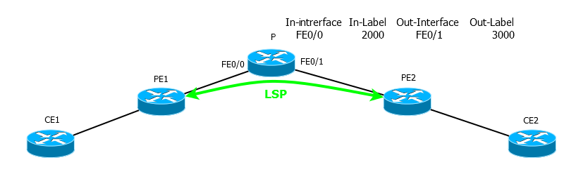
CE1 CE2. PE1 PE2 LSP.
CE1 TTL=2. P MPLS-, 2000. TTL 1, P , , TTL-expired CE1. ICMP-, CE1, ! MPLS 2000 3000 , FE0/1. .
E2, 2 IP.
2 MPLS .
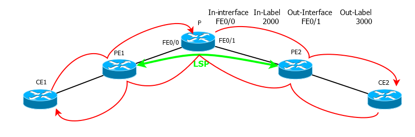
, 2 , .
TTL=3, PE2 2 , 1 — .
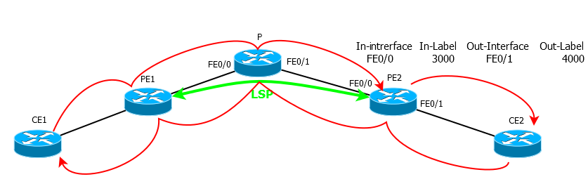
— - .
UPD: , «» TTL exceed 2, .
, MPLS, IP-, .
CE1 CE2. PE1 PE2 LSP.
CE1 TTL=2. P MPLS-, 2000. TTL 1, P , , TTL-expired CE1. ICMP-, CE1, ! MPLS 2000 3000 , FE0/1. .
E2, 2 IP.
2 MPLS .
, 2 , .
TTL=3, PE2 2 , 1 — .
— - .
UPD: , «» TTL exceed 2, .
17. cisco . ?
17: , ICMP- , ICMP-, . ICMP- , , ARP.
! :
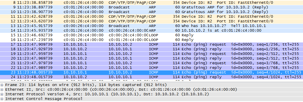
, ICMP- . ARP , ICMP . , 4 ICMP- 4 .
blog.ipspace.net/2007/04/why-is-first-ping-lost.html
! :
, ICMP- . ARP , ICMP . , 4 ICMP- 4 .
blog.ipspace.net/2007/04/why-is-first-ping-lost.html
18. , : A, B, C. 10/8, 172.16/12, 192.168/16?
18: , , — , . . IANA.
Dear YYY,
Thanks for contacting us.
We do not have the answer to your question and suggest you contact the authors of «Address Allocation for Private Internets» (RFC 1597), the document first setting these ranges aside. You can find details about the document here: www.rfc-editor.org/info/rfc1597
Kind regards,
1597 ) .
:
Dear YYY,
Thank you for your inquiry.
For more information about the private use space, see www.rfc-editor.org/rfc/rfc1918.txt.
As to why those specific blocks were chosen, we believe 10/8 was chosen because sri-nic.arpa (10.0.0.51) was embedded in pretty much every unix and multics system as the hardcoded source of hosts.txt and various other files. For the others, the decision was made that since a class A was allocated, there should be blocks of class Bs and Cs too. It could just be that those blocks were available.
Hope that helps.
Best regards,
Michelle Cotton
Manager, IANA Services
ICANN
- . .
, , , . , , .
? ?
— . , ? 192.168.1.110/24 , 192.168.1.0/24. .
— . , , . .
, , ?
, , , , .
:
? .
UPD :
, 4 «Interworking with TCP/IP» . , . , UNIX' , .. (192.168.1.255/24), — , «» .
. , , , . , ? ( 192.168.1/24, 192.168.1.110/24)
.
Source: https://habr.com/ru/post/189268/
All Articles