IR controller for domestic air conditioner or reverse engineering remote control
Greetings, dear habrachiteli! In this article, the first for me, I wanted to share my research and developments. Having air conditioning in my apartment, I felt the need to manage it when I was not at home. Returning from the cottage or just from work and turning on the air conditioner, you have to wait for a while until the heat subsides. And you want to come to the already light cool.
"That would be possible to remotely turn on the condition ..." - I thought.
So, I have a Panasonic CS-XE9DKE split system. The idea to control the air conditioner came down to creating "its" IR remote control. Let's call it "IR controller". And controlling the controller itself is the tenth task. And it depends on the specific place of application. For example, it would be more convenient for me to manage from a home server via WizFi200 (only to get it for reasonable money is problematic). My parents - by sending SMS (on SIM900) to the controller number. Other options are possible. But this is not the main thing I wanted to talk about.
So how does the native remote transmit the command? Having the TSOP17XX IR receiver available, I began to analyze the data stream from the console. It turned out that the remote control sends 2 parcels with a small pause. The first is the heading, the second is the command. The title was always the same.
')
After reviewing the existing IR coding systems (RC5, RC6, NEC, JVC, and others), it became clear that something else was used here, although the principle is similar.
Singhal looks like this:
(active level - low)
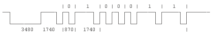
(bit values for an example, time in ms approximately)
At the beginning there is a pilot signal, followed by about half as long as the second pilot (pause), followed by the start bit, which is about 8 times shorter than the first pilot one. Next comes the bitstream. One bit is encoded by the length of the pause (high level). If the single pause is ZERO, if the pause is triple, this is ONE.
With only one button press, the remote sends 2 such packages. The first is the heading, the second is the command. The pause between the packages is about 10 ms.
Thus, the header contains 64 bits, or 8 bytes. First come the low bits.
The header data stream looks like this:
01000000000001000000011100100000000000000000000000000001100000
Or in bytes (HEX): 02 20 E0 40 00 00 00 06
It should be noted that the last byte is the checksum of all previous ones.
Now let's get a little distracted by the console itself. The remote has the following buttons:
There are also buttons for setting the current time, on and off timers (separately, independently).
The 3 buttons that are different from others are:
The point is that these buttons do not send all the settings, but enable / disable a specific mode. Those. These 3 modes can be turned on / off in any condition of the air conditioner.
Now back to the transfer protocol. Any command is preceded by a header.
Header bytes: 02 20 E0 40 00 00 00 06
Next comes the second package with the team.
Commands of three special buttons:
ion: 02 20 E0 04 80 48 33 01
oxyg: 02 20 E0 04 80 50 33 09
quiet: 02 20 E0 04 80 81 33 3A
I note that, as in the header, the last byte is a checksum.
But all the other buttons send a package with all the settings at once. And the format of this package is as follows:
Bit stream:
0100000000000100000001110010000000000000PNF1mmm00ccccc0000000001vvvvFFFF
hhhh0000nnnnnnnnnnnXfffffffffffY000010000000000010000000ttttttttt0000ssssssssss
Explanation of fields in order:
P - 1 if the ON / OFF button is pressed. When you click the other buttons here 0.
N - 1 if the on timer is set
F - 1 if off timer is set
mmm - mode (Mode). Auto - 0, heat - 4, cool - 3, dry - 2, fan - 6
ccccc - temperature. 16 to 30
vvvv - vertical direction. Auto - 15, 1 - to the ceiling, ... 5 - to the floor.
FFFF - fan speed. Auto - 10, F1 - 3, F2 - 4, F3 - 5, F4 - 6, F5 - 7
hhhh is the horizontal direction. Auto - 13, | | - 6, / / - 9, / | - 10, | \ - 11, \ \ - 12
nnnnnnnnnnn is the on time. The number of minutes in the day. (e.g. 16:00 = 960)
X - 1, if the set / reset timer button is pressed
fffffffffff - off time. The number of minutes in the day.
Y - 1 if the timer set / reset button is pressed
ttttttttttt - current time.
ssssssss - parcel checksum.
The signals X and Y are set to 1 only when the timers are set / reset, i.e. when SET or CANCEL is pressed directly. Not to be confused with N and F!
N and F - only report that the timers are on / off, while nnnnnnnnnnn or fffffffffff may be “not known” (0x600) at the moment. For example, when pressing the temperature increase button, if any timer is currently on, the value N / F is 1, and nnnnnnnnnnnn / fffffffffff c contains the specific time only for the on timer (for the off timer it contains 0x600). The air conditioner will change its N / F status only if the corresponding X / Y bit is 1.
If the on timer is not set, then the on time should be. 1536 = 0x600 = 0b11000000000. With the timer off time is similar. At least that is how the native remote is being sent.
Divide the bit stream into bytes and expand the bits:
Total command 19 bytes.
For testing, I assembled a circuit (borrowed here ) on a breadboard for solderless mounting. Components:
The difference between my circuit and the circuit by reference is that the LED is connected to PB1, and the base of the transistor is to PB3.
When the button is released on the PD7 port, timer 1 starts up in CTC mode with a signal output to PB1 / OC1A, as well as timer 2 with a output to PB3 / OC2 for the carrier frequency at which the main signal is modulated. Timers work with prescaler 8.
The current test implementation is able to send a header and a fixed command. But here I have a question - what should the depth of implementation of this controller be? After all, the controller can say “turn on cooling by 23 degrees”, or you can simply say “send the command” and transmit the entire bit stream with the already formed command. But you can also specify the timings. Then you can control various devices through one controller-emitter. I hope in the comments you will help me make a decision.
It is also planned to connect a pair of temperature sensors to monitor the room temperature and the airflow from the air conditioner. This is convenient for feedback (for example, SMS notification with current climate parameters) and control (did the air conditioner turn on?).
UPD
The story received a continuation in the article Wireless Controller of Household Air Conditioner in OpenHAB by Modbus via RF24Network .
"That would be possible to remotely turn on the condition ..." - I thought.
So, I have a Panasonic CS-XE9DKE split system. The idea to control the air conditioner came down to creating "its" IR remote control. Let's call it "IR controller". And controlling the controller itself is the tenth task. And it depends on the specific place of application. For example, it would be more convenient for me to manage from a home server via WizFi200 (only to get it for reasonable money is problematic). My parents - by sending SMS (on SIM900) to the controller number. Other options are possible. But this is not the main thing I wanted to talk about.
Reverse engineering
So how does the native remote transmit the command? Having the TSOP17XX IR receiver available, I began to analyze the data stream from the console. It turned out that the remote control sends 2 parcels with a small pause. The first is the heading, the second is the command. The title was always the same.
')
After reviewing the existing IR coding systems (RC5, RC6, NEC, JVC, and others), it became clear that something else was used here, although the principle is similar.
Singhal looks like this:
(active level - low)
(bit values for an example, time in ms approximately)
At the beginning there is a pilot signal, followed by about half as long as the second pilot (pause), followed by the start bit, which is about 8 times shorter than the first pilot one. Next comes the bitstream. One bit is encoded by the length of the pause (high level). If the single pause is ZERO, if the pause is triple, this is ONE.
With only one button press, the remote sends 2 such packages. The first is the heading, the second is the command. The pause between the packages is about 10 ms.
Thus, the header contains 64 bits, or 8 bytes. First come the low bits.
The header data stream looks like this:
01000000000001000000011100100000000000000000000000000001100000
Or in bytes (HEX): 02 20 E0 40 00 00 00 06
It should be noted that the last byte is the checksum of all previous ones.
Now let's get a little distracted by the console itself. The remote has the following buttons:
- ON / OFF (on / off)
- ± (temperature setting)
- O2 (oxygen generator)
- ion (ionizer)
- quiet (quiet mode)
- mode (auto, heat, cool, dry, fan)
- fan speed
- swing <> (horizontal direction)
- swing ^ v (vertical direction)
There are also buttons for setting the current time, on and off timers (separately, independently).
The 3 buttons that are different from others are:
- ion
- quiet
- O2
The point is that these buttons do not send all the settings, but enable / disable a specific mode. Those. These 3 modes can be turned on / off in any condition of the air conditioner.
Now back to the transfer protocol. Any command is preceded by a header.
Header bytes: 02 20 E0 40 00 00 00 06
Next comes the second package with the team.
Commands of three special buttons:
ion: 02 20 E0 04 80 48 33 01
oxyg: 02 20 E0 04 80 50 33 09
quiet: 02 20 E0 04 80 81 33 3A
I note that, as in the header, the last byte is a checksum.
But all the other buttons send a package with all the settings at once. And the format of this package is as follows:
Bit stream:
0100000000000100000001110010000000000000PNF1mmm00ccccc0000000001vvvvFFFF
hhhh0000nnnnnnnnnnnXfffffffffffY000010000000000010000000ttttttttt0000ssssssssss
Explanation of fields in order:
P - 1 if the ON / OFF button is pressed. When you click the other buttons here 0.
N - 1 if the on timer is set
F - 1 if off timer is set
mmm - mode (Mode). Auto - 0, heat - 4, cool - 3, dry - 2, fan - 6
ccccc - temperature. 16 to 30
vvvv - vertical direction. Auto - 15, 1 - to the ceiling, ... 5 - to the floor.
FFFF - fan speed. Auto - 10, F1 - 3, F2 - 4, F3 - 5, F4 - 6, F5 - 7
hhhh is the horizontal direction. Auto - 13, | | - 6, / / - 9, / | - 10, | \ - 11, \ \ - 12
nnnnnnnnnnn is the on time. The number of minutes in the day. (e.g. 16:00 = 960)
X - 1, if the set / reset timer button is pressed
fffffffffff - off time. The number of minutes in the day.
Y - 1 if the timer set / reset button is pressed
ttttttttttt - current time.
ssssssss - parcel checksum.
The signals X and Y are set to 1 only when the timers are set / reset, i.e. when SET or CANCEL is pressed directly. Not to be confused with N and F!
N and F - only report that the timers are on / off, while nnnnnnnnnnn or fffffffffff may be “not known” (0x600) at the moment. For example, when pressing the temperature increase button, if any timer is currently on, the value N / F is 1, and nnnnnnnnnnnn / fffffffffff c contains the specific time only for the on timer (for the off timer it contains 0x600). The air conditioner will change its N / F status only if the corresponding X / Y bit is 1.
If the on timer is not set, then the on time should be. 1536 = 0x600 = 0b11000000000. With the timer off time is similar. At least that is how the native remote is being sent.
Divide the bit stream into bytes and expand the bits:
 00000010 02
 00100000 20
 11100000 E0
 00000100 04
 00000000 00
 0mmm1FNP Mode << 4 + 8 + FlagOFF << 2 + FlagON << 1 + Power
 00ccccc0 Temperature << 1
 10,000,000 80
 FFFFvvvv Fan << 4 + Vert
 0000hhhh Horiz
 nnnnnnnn OnTime & 0xFF
 ffffXnnn OnTime >> 8 + OffTime & 0x0F + ChangeOn << 3
 Yfffffff OffTime >> 4 + ChangeOff << 7
 00010000 10
 00000000 00
 00000001 01
 tttttttt Time & 0xFF
 00000ttt Time >> 8
 ssssssss sum
Total command 19 bytes.
Controller
For testing, I assembled a circuit (borrowed here ) on a breadboard for solderless mounting. Components:
- atmega8
- IR diode
- kt361 transistor
- 470 resistor to transistor base
- resistor 220 limits diode current
- 10k resistor on RESET
The difference between my circuit and the circuit by reference is that the LED is connected to PB1, and the base of the transistor is to PB3.
When the button is released on the PD7 port, timer 1 starts up in CTC mode with a signal output to PB1 / OC1A, as well as timer 2 with a output to PB3 / OC2 for the carrier frequency at which the main signal is modulated. Timers work with prescaler 8.
Firmware
Source code for AVR Studio 4.
#include <avr/io.h> #include <avr/interrupt.h> #define F_CPU 8000000 #define LED_CARIER DDB3 #define LED_SIGNAL DDB1 #define BASE 480 #define PAUSE 10000 #define START_1 BASE*8 #define START_2 BASE*4 #define DELIM 520 #define PULSE1 BASE*3 #define PULSE0 BASE unsigned char state = 0; unsigned char byteIndex = 0; unsigned char frameIndex = 0; unsigned char bit = 0; unsigned char phase = 0; unsigned char packetLen = 0; unsigned char process = 0; char header[] = {0x02, 0x20, 0xE0, 0x04, 0x00, 0x00, 0x00, 0x06}; char cmd_ion[] = {0x02, 0x20, 0xE0, 0x04, 0x80, 0x48, 0x33, 0x01}; char cmd_oxygen[] = {0x02, 0x20, 0xE0, 0x04, 0x80, 0x50, 0x33, 0x09}; char cmd_quiet[] = {0x02, 0x20, 0xE0, 0x04, 0x80, 0x81, 0x33, 0x3A}; char* data; char* cmd; unsigned char cmdLen; void stop(); ISR(SIG_OUTPUT_COMPARE1A) { switch (state) { case 0: OCR1AH = START_2 / 256; OCR1AL = START_2 % 256; state = 1; break; case 1: OCR1AH = DELIM / 256; OCR1AL = DELIM % 256; state = 2; byteIndex = 0; frameIndex++; if (frameIndex == 1) { data = header; packetLen = 8; } else { data = cmd; packetLen = cmdLen; } bit = 0; phase = 0; break; case 2: if (byteIndex < packetLen) { if (phase == 0) { if (data[byteIndex]&(1 << bit)) { OCR1AH = PULSE1 / 256; OCR1AL = PULSE1 % 256; } else { OCR1AH = PULSE0 / 256; OCR1AL = PULSE0 % 256; } } else { OCR1AH = DELIM / 256; OCR1AL = DELIM % 256; bit++; if (bit == 8) { bit = 0; byteIndex++; } } phase = 1 - phase; } else { OCR1AH = PAUSE / 256; OCR1AL = PAUSE % 256; if (frameIndex == 2) { stop(); } else { state = 3; } } break; case 3: OCR1AH = START_1 / 256; OCR1AL = START_1 % 256; state = 0; break; } } void start() { state = 0; byteIndex = 0; frameIndex = 0; packetLen = sizeof (header); TCNT1H = 0; TCNT1L = 0; OCR1AH = START_1 / 256; OCR1AL = START_1 % 256; TCCR1A = (1 << COM1A0); TCCR1B = (1 << WGM12) | (1 << CS11); TCNT2 = 0; OCR2 = 13; TCCR2 = (1 << WGM21) | (1 << COM20) | (1 << CS21); TIMSK = (1 << OCIE1A); sei(); } void stop() { cli(); TCCR2 = (1 << WGM21) | (1 << COM20); TCCR1A = (1 << FOC1A); TCCR1B = (1 << WGM12) | (0 << CS12) | (0 << CS11) | (0 << CS10); TIMSK = 0; PORTB = (1 << LED_SIGNAL) | (1 << LED_CARIER); process = 0; } int main(void) { process = 0; PORTB = (1 << LED_SIGNAL) | (1 << LED_CARIER); DDRB = (1 << LED_SIGNAL) | (1 << LED_CARIER); PORTD = (1 << 7); // PD7 input, pull up DDRD = 0; while (1) { int but = (PIND & (1 << PD7)); if (process == 0 && but == 0) { process = 1; } else if (process == 1 && but != 0) { process = 2; cmd = cmd_oxygen; cmdLen = 8; start(); } } } Conclusion
The current test implementation is able to send a header and a fixed command. But here I have a question - what should the depth of implementation of this controller be? After all, the controller can say “turn on cooling by 23 degrees”, or you can simply say “send the command” and transmit the entire bit stream with the already formed command. But you can also specify the timings. Then you can control various devices through one controller-emitter. I hope in the comments you will help me make a decision.
It is also planned to connect a pair of temperature sensors to monitor the room temperature and the airflow from the air conditioner. This is convenient for feedback (for example, SMS notification with current climate parameters) and control (did the air conditioner turn on?).
UPD
The story received a continuation in the article Wireless Controller of Household Air Conditioner in OpenHAB by Modbus via RF24Network .
Source: https://habr.com/ru/post/189142/
All Articles