Raytracing render on C
Having experience in developing one of the high-level programming languages, as well as interest in tasks from various computer science fields, I finally found the opportunity to master another tool — the C programming language. Therefore, it was decided to implement a Ray tracing render from scratch (since I am fond of computer graphics since school times).
In this article I want to share my own approach and the results obtained.
Imagine that we have a camera (for simplicity, we assume that our camera is a material point). We also have a design plane, which is a set of pixels. Now, from the camera, to each pixel of the design plane, we will conduct vectors ( primary rays ) and for each beam find the nearest object of the scene that it intersects. Color that corresponds to the intersection point, you can paint the corresponding pixel on the design plane. Repeating this procedure for all points of the design plane - we will get an image of a three-dimensional scene. If we confine ourselves only to these operations, then the resulting algorithm will be called Ray casting .
')

The combination of the above techniques allows you to get quite realistic images. I also want to focus on the following features of the algorithm:
All objects are stored in a heap. Render operates with an array of pointers to 3D objects (in fact, all objects are still packed in a kd-tree, but for now we will assume that the tree is missing). At the moment there are 2 types of primitives: triangles and spheres.
The raytracing algorithm is independent of the geometry of the objects: the object structure is not important for the renderer, in fact only functions are needed to calculate the intersections of the figure with the ray.
In terms of OOP, this can be implemented using the concept of an interface : each object provides implementations of the corresponding methods, which allows processing various primitives in a unified way.
The C programming language has no syntactic constructs for programming in the OOP paradigm, but in this case structures and function pointers come to the rescue .
Render operates with generalized structures (Object3d) containing a pointer to the data area in which the actual parameters of the 3D object are stored, as well as pointers to functions that can correctly handle this data area.
This approach allows you to localize the code relating to each 3D primitive in a separate file. Consequently, it is quite easy to make changes to the structures of 3D objects (for example, add support for textures or normal maps), or even add new 3D primitives. At the same time - no need to make changes to the render code. It turned out something like encapsulation .
For the sake of justice, it is worth noting that such an architecture entails a lot of pointer juggling.
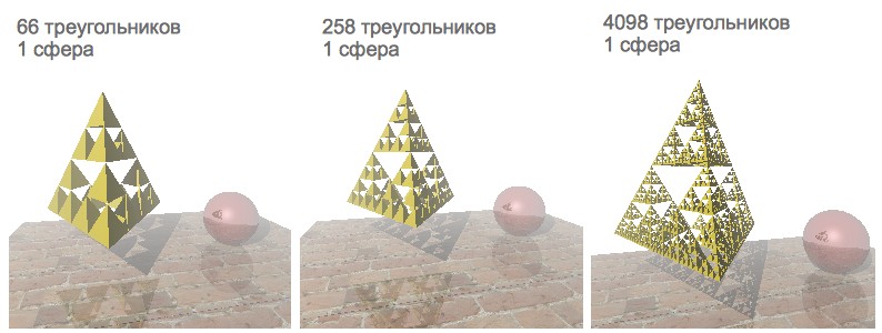
As a test case, I decided to visualize the scene with the “Sierpinski Pyramid” fractal, a mirror sphere and a stand with a texture. It is rather convenient to use the Sierpinski pyramid to test the rendering speed. By setting different levels of recursion, you can generate a different number of triangles:
Initially, the rendering speed was satisfactory only for those scenes that contained less than a thousand polygons. Since I have a 4-core processor - it was decided to speed up the rendering by paralleling.
First impression: Java Threads semantics is very close to pthreads. Therefore, there were no particular problems with understanding the POSIX model. It was decided to sip your Thread Pool :-)
Thread Pool contained a queue for the task. Each task was a structure containing a link to the function to be executed, as well as a link to the list of arguments. Access to the queue of tasks was regulated by means of mutex and condition variable. For convenience, the entire rendering is encapsulated in a separate function, one of whose arguments is the number of threads:
This function contained a code, a rendering rendering loop and a thread pool, whose duties included:
But, unfortunately, on a 2-core nuclear, the render periodically hung up or fell with an Abort trap 6 error (and on a 4-core nuclear, this has never been reproduced). I tried to fix this sad bug, but soon I found a more attractive solution.
OpenMP takes all the care of creating and distributing tasks, and also organizes a barrier to wait for the rendering to complete. Just add a few directives to parallelize the single-threaded code, and the hang bugs disappeared :-)
The rendering accelerated a bit, but, alas, scenes containing more than a thousand primitives were still rendered very slowly.
Calculating the intersection of a ray with primitives is a relatively resource-intensive procedure. The problem is that for each ray, the intersections with all primitives of the scene are checked (the closest primitive is searched for, crossed by the ray). Is it possible to somehow exclude those objects with which the ray does not exactly intersect?
Let's break the stage with the objects into two parts: “left” and “right” (we denote them as L and R, respectively):
Since we divide the scene into parts parallel to the coordinate axes, it is relatively quick to calculate which part of the scene the ray crosses. The following options are possible:
But, in exactly the same way, in order to reduce the number of viewed polygons - you can continue to recursively split the scene into smaller sections. The resulting hierarchical structure containing the segments of the scene, with primitives attached to them is called the kd-tree .
Let's, for example, consider the process of ray tracing 2 :

Thanks to the organization of the tree data structure, we have excluded those objects that are not necessarily intersected by a ray. But there is still a very important nuance - the effectiveness of a kd-tree depends on how we break the stage into parts. How to choose the right scene splitting sites?
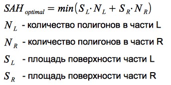
The probability of hitting the beam in any segment of the scene is proportional to the area of this segment. The more primitives are contained in the part of the scene - the more intersections will need to be calculated when the beam hits this segment. Thus, it is possible to formulate a partitioning criterion: it is necessary to minimize the product of the number of primitives and the area of the segment in which they are contained. This criterion is called Surface Area Heuristic (SAH):
Let's take a simple example, consider heuristics in action:
Thus, the use of SAH allows you to effectively separate the empty space and 3D objects - which has a very positive effect on the performance of the render.
The renderer has the ability to calculate the average number of intersections per 1 pixel of the image: every time the intersection of a ray with an object is calculated, the counter value increases, after the rendering is completed, the counter value is divided by the number of pixels in the image.
The results obtained vary for different scenes (since the construction of a kd-tree depends on the relative position of the primitives). The graphs show the dependence of the average number of intersections per 1 pixel of the image on the number of primitives:
It can be noted that this value is significantly less than the number of primitives contained in the scene (if there were no kd-tree, then a linear relationship would be obtained, since for each ray we would have to look for an intersection with all N primitives). In fact, using the kd-tree, we reduced the complexity of the raytracing algorithm from O (N) to O (log (N)).
For the sake of justice, it is worth noting that one of the drawbacks of this solution is the resource-intensive construction of the kd-tree. But for static scenes, this is not critical: we loaded the scene, waited until a tree was built - and you can go traveling with a camera around the scene :-)
Scene containing 16386 triangles:
Having learned to render a large number of primitives - there was a desire to load 3D models. A rather simple and widespread format was chosen - OBJ : the model is stored in a text file that contains a list of vertices and a list of polygons (each polygon is defined by points from the list of vertices).
In the process of writing the parser OBJ format, it was noted that many models also contain a list of normals for each vertex of the polygon. Vertex normal vectors can be interpolated to obtain a normal vector at any point of the polygon — this technique allows you to simulate smooth surfaces (see Phong shading ). This feature was fairly easy to implement within the current render architecture (you just needed to add normal vectors to the Triangle3d structure, and write a function that interpolates them for any point of the polygon).
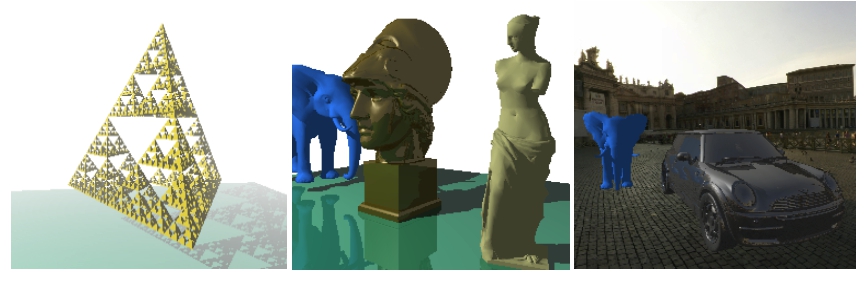
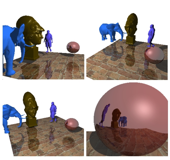
An example of a scene renderer containing about 19,000 polygons:

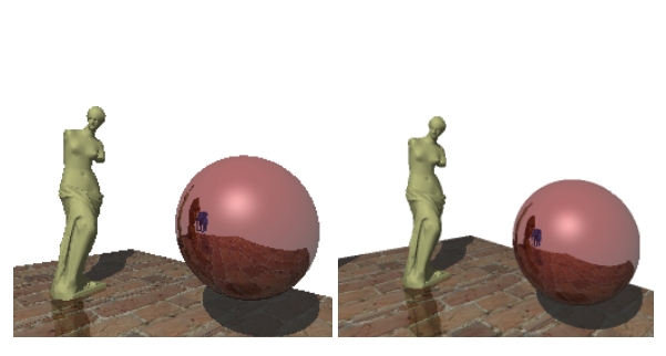
An example of a scene renderer containing approximately 22,000 polygons:
For the sake of interest, I decided to add a skybox and upload car models:
I am glad that I chose this task during the study of C - because, it allowed to learn various aspects of the language ecosystem, and get beautiful results.
Sources of render on githaba: github.com/lagodiuk/raytracing-render (in the project description - how to run the demo).
In the process of studying C, 2 books helped me a lot:
Also, I want to thank dmytrish for consultations on some of the nuances of C, and for the written frontend for rendering (using GLUT) - in order to display the scene in the window, and using the keyboard to move and rotate the camera.
I also want to recommend a very useful resource: ray-tracing.ru - here, in an accessible form, various algorithms used for photorealistic rendering are described (in particular, kd-trees and SAH).
PS
Several videos created during the rendering process:
UPD:
It turned out to speed up the construction of the tree. Details in the comments branch: habrahabr.ru/post/187720/#comment_6580722
UPD 2:
After discussion in this thread of comments: habrahabr.ru/post/187720/#comment_6579384 - anti-aliasing was implemented. Thank you all for the ideas. Now rendered images look more beautiful :)
In this article I want to share my own approach and the results obtained.
Some words about raytracing
Imagine that we have a camera (for simplicity, we assume that our camera is a material point). We also have a design plane, which is a set of pixels. Now, from the camera, to each pixel of the design plane, we will conduct vectors ( primary rays ) and for each beam find the nearest object of the scene that it intersects. Color that corresponds to the intersection point, you can paint the corresponding pixel on the design plane. Repeating this procedure for all points of the design plane - we will get an image of a three-dimensional scene. If we confine ourselves only to these operations, then the resulting algorithm will be called Ray casting .
')
Recursive Ray casting == Ray tracing
- From the point of intersection of the primary beam with the object of the scene, you can release a secondary beam - directed to the light source. If it intersects any object of the scene, then this point of the object is in the shadow. This technique allows to obtain geometrically correct shadows .
- If an object has a mirror surface, then according to the laws of geometric optics, it is possible to calculate the reflected beam - and start the ray tracing procedure for it (recursively). Then mix the resulting color from the specular color with its own surface color. This technique allows you to simulate mirror surfaces (in this way you can simulate transparent surfaces ).
- You can calculate the distance from the camera to the point of intersection of the beam with the object of the scene. The distance value can be used to simulate fog : the farther the object is from the camera, the lower the intensity of its color (for calculations, you can use, for example, the exponential function of decreasing intensity).
The combination of the above techniques allows you to get quite realistic images. I also want to focus on the following features of the algorithm:
- The color of each pixel can be calculated independently of the others (since the rays emitted from the camera have no effect on each other - they can be processed in parallel)
- The algorithm does not contain restrictions on the geometry of objects (you can use a rich set of primitives: planes, spheres, cylinders, etc.)
Render architecture
All objects are stored in a heap. Render operates with an array of pointers to 3D objects (in fact, all objects are still packed in a kd-tree, but for now we will assume that the tree is missing). At the moment there are 2 types of primitives: triangles and spheres.
How to teach render to operate with different primitives?
The raytracing algorithm is independent of the geometry of the objects: the object structure is not important for the renderer, in fact only functions are needed to calculate the intersections of the figure with the ray.
In terms of OOP, this can be implemented using the concept of an interface : each object provides implementations of the corresponding methods, which allows processing various primitives in a unified way.
The C programming language has no syntactic constructs for programming in the OOP paradigm, but in this case structures and function pointers come to the rescue .
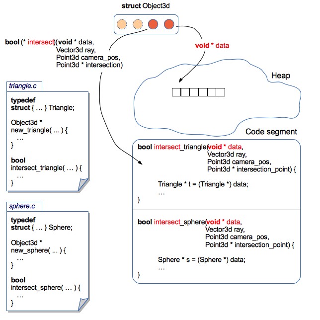
Render operates with generalized structures (Object3d) containing a pointer to the data area in which the actual parameters of the 3D object are stored, as well as pointers to functions that can correctly handle this data area.
Description of the structure of Object3d from the source of the render
typedef struct { // , // : , ( ), // : , , .. void * data; // , , // data Boolean (*intersect)(const void * data, const Point3d ray_start_point, const Vector3d ray, // Point3d * const intersection_point); // // // // :) Color (*get_color)(const void * data, const Point3d intersection_point); // ( ) // - // , - Vector3d (*get_normal_vector)(const void * data, const Point3d intersection_point); // Object3d // , // , void (*release_data)(void * data); } Object3d; This approach allows you to localize the code relating to each 3D primitive in a separate file. Consequently, it is quite easy to make changes to the structures of 3D objects (for example, add support for textures or normal maps), or even add new 3D primitives. At the same time - no need to make changes to the render code. It turned out something like encapsulation .
As an example: the sphere code from the source of the render
sphere.c
// ... typedef struct { Point3d center; Float radius; Color color; } Sphere; // ... // "" Object3d * new_sphere(const Point3d center, const Float radius, const Color color) { Sphere * sphere = malloc(sizeof(Sphere)); sphere->center = center; sphere->radius = radius; sphere->color = color; // 3D Object3d * obj = malloc(sizeof(Object3d)); obj->data = sphere; // , Sphere obj->get_color = get_sphere_color; obj->get_normal_vector = get_sphere_normal_vector; obj->intersect = intersect_sphere; obj->release_data = release_sphere_data; return obj; } // // static Color get_sphere_color(const void * data, const Point3d intersection_point) { const Sphere * sphere = data; return sphere->color; } // // Bump Mapping static Vector3d get_sphere_normal_vector(const void * data, const Point3d intersection_point) { const Sphere * sphere = data; // vector3dp - , Vector3d n = vector3dp(sphere->center, intersection_point); normalize_vector(&n); return n; } // static Boolean intersect_sphere(const void * data, const Point3d ray_start_point, const Vector3d ray, Point3d * const intersection_point) { const Sphere * sphere = data; // - // GitHub } // "" void release_sphere_data(void * data) { Sphere * sphere = data; // - free(sphere); } An example of how to operate with different primitives, regardless of their implementation
void example(void) { Object3d * objects[2]; // , (10, 20, 30) 100 objects[0] = new_sphere(point3d(10, 20, 30), 100, rgb(255, 0, 0)); // (0, 0, 0), (100, 0, 0) (0, 100, 0) objects[1] = new_triangle(point3d(0, 0, 0), point3d(100, 0, 0), point3d(0, 100, 0), rgb(0, 255, 0)); Point3d camera = point3d(0, 0, -100); Vector3d ray = vector3df(0, -1, 0); int i; for(i = 0; i < 2; i++) { Object3d * obj = objects[i]; Point3d intersection_point; if(obj->intersect(obj->data, camera, ray, &intersection_point)) { // Color c = obj->get_color(obj->data, intersection_point); // - :-) // , // , objects! } } } For the sake of justice, it is worth noting that such an architecture entails a lot of pointer juggling.
Rendering speed
As a test case, I decided to visualize the scene with the “Sierpinski Pyramid” fractal, a mirror sphere and a stand with a texture. It is rather convenient to use the Sierpinski pyramid to test the rendering speed. By setting different levels of recursion, you can generate a different number of triangles:
Initially, the rendering speed was satisfactory only for those scenes that contained less than a thousand polygons. Since I have a 4-core processor - it was decided to speed up the rendering by paralleling.
Posix threads
First impression: Java Threads semantics is very close to pthreads. Therefore, there were no particular problems with understanding the POSIX model. It was decided to sip your Thread Pool :-)
Thread Pool contained a queue for the task. Each task was a structure containing a link to the function to be executed, as well as a link to the list of arguments. Access to the queue of tasks was regulated by means of mutex and condition variable. For convenience, the entire rendering is encapsulated in a separate function, one of whose arguments is the number of threads:
The signature of the encapsulating rendering function
void render_scene(const Scene * const scene, const Camera * const camera, Canvas * canvas, const int num_threads); // Scene 3D , , // Camera , // Canvas 2 - This function contained a code, a rendering rendering loop and a thread pool, whose duties included:
- split the canvas into several pieces
- for each part of the canvas to form a separate task for rendering
- send all tasks to pool and wait for completion
But, unfortunately, on a 2-core nuclear, the render periodically hung up or fell with an Abort trap 6 error (and on a 4-core nuclear, this has never been reproduced). I tried to fix this sad bug, but soon I found a more attractive solution.
Openmp
OpenMP takes all the care of creating and distributing tasks, and also organizes a barrier to wait for the rendering to complete. Just add a few directives to parallelize the single-threaded code, and the hang bugs disappeared :-)
Source Rendering Function
void render_scene(const Scene * const scene, const Camera * const camera, Canvas * canvas, const int num_threads) { const int width = canvas->width; const int height = canvas->height; const Float focus = camera->focus; // omp_set_num_threads(num_threads); int x; int y; // , :-) #pragma omp parallel private(x, y) #pragma omp for collapse(2) schedule(dynamic, CHUNK) for(x = 0; x < width; x++) { for(y = 0; y < height; y++) { const Vector3d ray = vector3df(x, y, focus); const Color col = trace(scene, camera, ray); set_pixel(i, j, col, canvas); } } } The rendering accelerated a bit, but, alas, scenes containing more than a thousand primitives were still rendered very slowly.
Calculating the intersection of a ray with primitives is a relatively resource-intensive procedure. The problem is that for each ray, the intersections with all primitives of the scene are checked (the closest primitive is searched for, crossed by the ray). Is it possible to somehow exclude those objects with which the ray does not exactly intersect?
Kd-tree
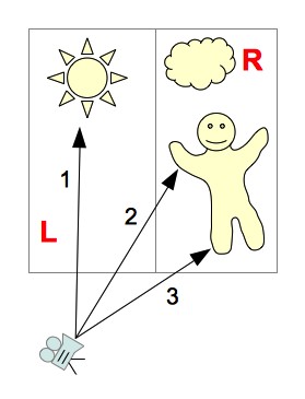
Let's break the stage with the objects into two parts: “left” and “right” (we denote them as L and R, respectively):
Since we divide the scene into parts parallel to the coordinate axes, it is relatively quick to calculate which part of the scene the ray crosses. The following options are possible:
- The beam crosses only part of the scene L
You can not view the objects contained in part R
(ray 1 in the picture) - The beam crosses only part of the scene R
Can not view objects contained in part L
(ray 3 in the picture) - The beam first crosses part of scene L, and then part of scene R
First we look at the objects belonging to the parts of the scene L - if the intersection was found, then the objects belonging to the parts of the scene R can be not viewed. If the beam does not intersect any object from part L - you will have to look at objects from part R
(ray 2 in the picture) - The beam first crosses part of scene R, and then part of scene L
The same logic of the search for intersections, as in the previous version (only first consider the part of the scene R)
But, in exactly the same way, in order to reduce the number of viewed polygons - you can continue to recursively split the scene into smaller sections. The resulting hierarchical structure containing the segments of the scene, with primitives attached to them is called the kd-tree .
Let's, for example, consider the process of ray tracing 2 :
- The beam first crosses the left segment of the scene (L), then the right - R
- From part L - the beam intersects only the LL segment
- LL segment contains no objects.
- Go to the right half of the scene - R
- In the right half of the scene, the beam first crosses the RL segment, and then the RR
- In part of the RL scene, the intersection of the beam with the object was found
- Tracing completed
Thanks to the organization of the tree data structure, we have excluded those objects that are not necessarily intersected by a ray. But there is still a very important nuance - the effectiveness of a kd-tree depends on how we break the stage into parts. How to choose the right scene splitting sites?
Surface Area Heuristic
The probability of hitting the beam in any segment of the scene is proportional to the area of this segment. The more primitives are contained in the part of the scene - the more intersections will need to be calculated when the beam hits this segment. Thus, it is possible to formulate a partitioning criterion: it is necessary to minimize the product of the number of primitives and the area of the segment in which they are contained. This criterion is called Surface Area Heuristic (SAH):
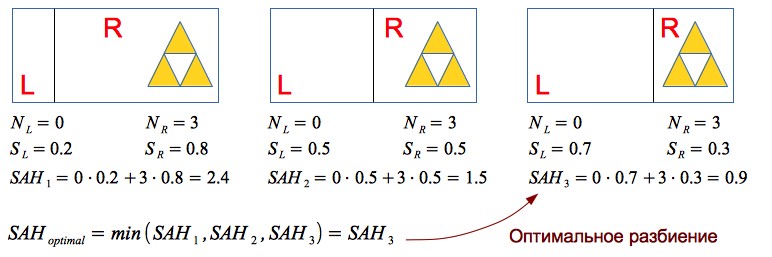
Let's take a simple example, consider heuristics in action:
Thus, the use of SAH allows you to effectively separate the empty space and 3D objects - which has a very positive effect on the performance of the render.
Observations
The renderer has the ability to calculate the average number of intersections per 1 pixel of the image: every time the intersection of a ray with an object is calculated, the counter value increases, after the rendering is completed, the counter value is divided by the number of pixels in the image.
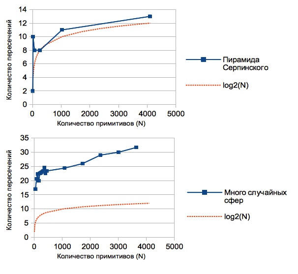
The results obtained vary for different scenes (since the construction of a kd-tree depends on the relative position of the primitives). The graphs show the dependence of the average number of intersections per 1 pixel of the image on the number of primitives:
It can be noted that this value is significantly less than the number of primitives contained in the scene (if there were no kd-tree, then a linear relationship would be obtained, since for each ray we would have to look for an intersection with all N primitives). In fact, using the kd-tree, we reduced the complexity of the raytracing algorithm from O (N) to O (log (N)).
For the sake of justice, it is worth noting that one of the drawbacks of this solution is the resource-intensive construction of the kd-tree. But for static scenes, this is not critical: we loaded the scene, waited until a tree was built - and you can go traveling with a camera around the scene :-)
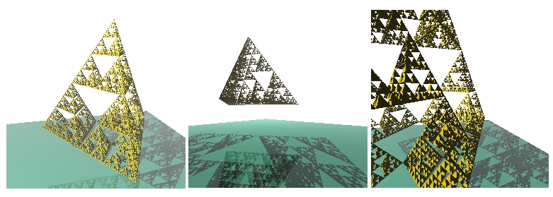
Scene containing 16386 triangles:
Loading models
Having learned to render a large number of primitives - there was a desire to load 3D models. A rather simple and widespread format was chosen - OBJ : the model is stored in a text file that contains a list of vertices and a list of polygons (each polygon is defined by points from the list of vertices).
An example of a very simple model: tetrahedron.obj
# tetrahedron
# vertexes:
v 1.00 1.00 1.00
v 2.00 1.00 1.00
v 1.00 2.00 1.00
v 1.00 1.00 2.00
# triangles:
f 1 3 2
f 1 4 3
f 1 2 4
f 2 3 4
# vertexes:
v 1.00 1.00 1.00
v 2.00 1.00 1.00
v 1.00 2.00 1.00
v 1.00 1.00 2.00
# triangles:
f 1 3 2
f 1 4 3
f 1 2 4
f 2 3 4
In the process of writing the parser OBJ format, it was noted that many models also contain a list of normals for each vertex of the polygon. Vertex normal vectors can be interpolated to obtain a normal vector at any point of the polygon — this technique allows you to simulate smooth surfaces (see Phong shading ). This feature was fairly easy to implement within the current render architecture (you just needed to add normal vectors to the Triangle3d structure, and write a function that interpolates them for any point of the polygon).
Triangle3d structure from render sources
typedef struct { // Point3d p1; Point3d p2; Point3d p3; // , // - Vector3d norm; Color color; Material material; // - , color Canvas * texture; // // , Point2d t1; Point2d t2; Point2d t3; // // Vector3d n1; Vector3d n2; Vector3d n3; // // } Triangle3d; An example of a scene renderer containing about 19,000 polygons:
An example of a scene renderer containing approximately 22,000 polygons:
For the sake of interest, I decided to add a skybox and upload car models:
The scene contains about 100,000 polygons (kd-tree was built a few minutes)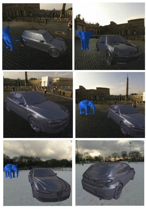
Conclusion
I am glad that I chose this task during the study of C - because, it allowed to learn various aspects of the language ecosystem, and get beautiful results.
Sources of render on githaba: github.com/lagodiuk/raytracing-render (in the project description - how to run the demo).
In the process of studying C, 2 books helped me a lot:
- Brian Kernigan, Dennis Ritchie - C Programming Language - initially had some difficulty reading this book. But after reading Head First C - I returned to this book again. In this book there are many examples and tasks that helped in the study
- David Griffiths, Dawn Griffiths - Head First C - I liked this book very much because it gives a general vision of the ecosystem of the C language (how memory is organized, how it works at the OS level, make, valgrind, POSIX streams, unit testing, described in general terms and there are even a few pages about Arduino)
Also, I want to thank dmytrish for consultations on some of the nuances of C, and for the written frontend for rendering (using GLUT) - in order to display the scene in the window, and using the keyboard to move and rotate the camera.
I also want to recommend a very useful resource: ray-tracing.ru - here, in an accessible form, various algorithms used for photorealistic rendering are described (in particular, kd-trees and SAH).
PS
Several videos created during the rendering process:
Sierpinski Pyramid in the Fog
Cube, man, lantern, teapot and Sierpinski pyramid :-)
UPD:
It turned out to speed up the construction of the tree. Details in the comments branch: habrahabr.ru/post/187720/#comment_6580722
UPD 2:
After discussion in this thread of comments: habrahabr.ru/post/187720/#comment_6579384 - anti-aliasing was implemented. Thank you all for the ideas. Now rendered images look more beautiful :)
Source: https://habr.com/ru/post/187720/
All Articles