Reliable (non-extreme) overclocking of the processor and memory for ASUS motherboards with an i7 processor
UEFI settings for ASUS Z77 motherboards are considered on the example of ASUS PZ77-V LE with Ivy Bridge i7 processor. The optimal parameters were chosen for some complex UEFI-settings that allow you to get a successful overclocking without undue risk. The user consistently gets acquainted with the basic concepts of overclocking and provides reliable and non-extreme overclocking of the processor and memory of ASUS Z77 motherboards. For simplicity, UEFI English is used.
Post cool adopted on the site overclockers. This is understandable, since on this site there are mostly reckless,reckless users involved in extreme overclocking.
All actions related to overclocking are performed in the AI Tweaker menu (UEFI Advanced Mode) by setting the AI Overclock Tuner parameter to Manual (Fig. 1).
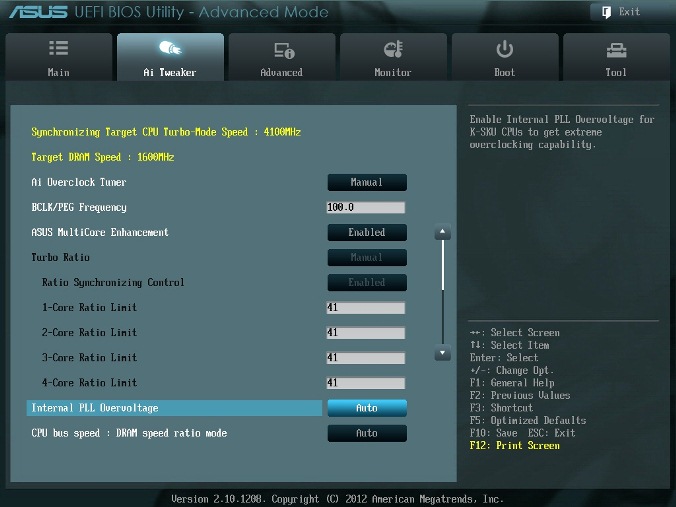
Fig. one
The BCLK / PEG Frequency parameter (hereinafter referred to as BCLK) in fig. 1 becomes available when Ai Overclock Tuner \ XMP or Ai Overclock Tuner \ Manual is selected. A BCLK frequency of 100 MHz is the base frequency. The main parameter of overclocking is the frequency of the processor core, obtained by multiplying this frequency by a parameter - a processor multiplier. The final frequency is displayed in the upper left part of the Ai Tweaker window (in Figure 1, it is 4.1 GHz). The BCLK frequency also adjusts the memory frequency, bus speed, and so on.
A possible increase in this parameter during overclocking is not large - most processors allow you to increase this frequency only to 105 MHz. Although there are separate samples of processors and motherboards, for which this value is equal to 107 MHz and more. With careful acceleration, taking into account the fact that in the future additional devices will be installed in the computer, this parameter is recommended to be left at 100 MHz (Fig. 1).
')
When this option is enabled (Enabled in Figure 1), the ASUS policy for Turbo mode is adopted. If the option is disabled, the Intel policy for Turbo mode will be applied. For all configurations during overclocking, it is recommended to enable this parameter (Enabled). Turning this off can be used if you want to run the processor using Intel policies, without overclocking.
In the window of Fig. 1 set the Manual mode for this parameter. Turning to the Advanced \ ... \ CPU Power Management Configuration menu (Fig. 2), we set the multiplier 41.
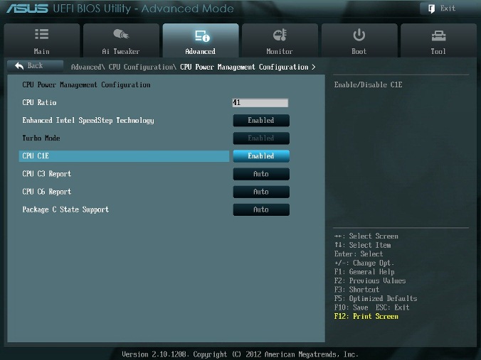
Fig. 2
Go back to the AI Tweaker menu and check the value of the multiplier (Fig. 1).
For very careful users, we can recommend an initial multiplier value of 40 or even 39. The maximum multiplier value for non-extreme acceleration is usually less than 45.
Increasing (overclocking) the operating voltage for internal phase automatic frequency control (PLL) allows you to increase the operating frequency of the processor core. Selecting Auto will automatically enable this option only when increasing the multiplier of the processor core beyond a certain threshold.
For good samples of processors, this parameter should be left at Auto (Fig. 1) during acceleration up to factor 45 (up to a processor operating frequency of 4.5 GHz).
Note that the stability of the wake-up mode can be affected when this parameter is set to Enabled. If it is detected that your processor will not accelerate to 4.5 GHz without setting this parameter to the Enabled state, but the system is not able to wake up from sleep mode, then the only choice is to operate at a lower frequency with a multiplier less than 45. For extreme Acceleration with multipliers equal to or greater than 45 is recommended to be set to Enabled. With careful acceleration choose Auto. (Fig. 1).
This parameter can be left in the Auto state (Fig. 1) in order to apply further changes during overclocking and tuning the memory frequency.
This parameter is visible in fig. 3. It is used to select the frequency of the memory.
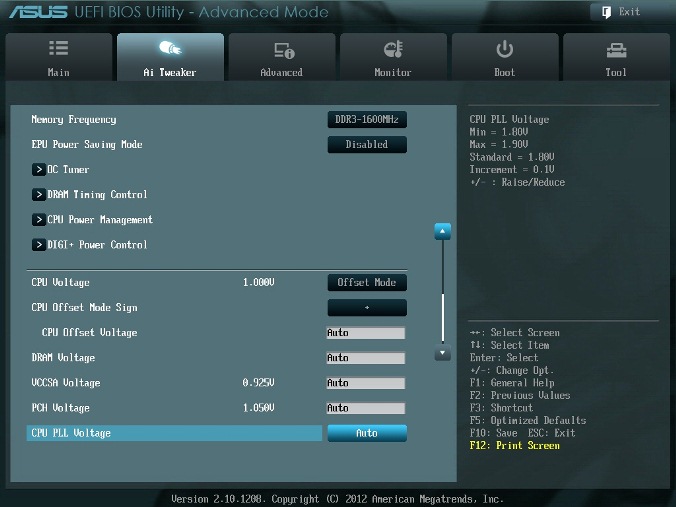
Fig. 3
The Memory Frequency parameter is determined by the BCLK frequency and the CPU bus speed parameter: DRAM speed ratio mode. The memory frequency is displayed and selected in the drop-down list. The set value can be checked in the upper left corner of the Ai Tweaker menu. For example, in fig. 1 we see that the frequency of the memory is 1600 MHz.
Note that Ivy Bridge processors have a wider range of memory frequency settings than the previous generation of Sandy Bridge processors. When overclocking the memory, together with an increase in the frequency of the BCLK, you can make more detailed control of the frequency of the memory bus and get the maximum possible (but possibly unreliable) results during extreme overclocking.
For reliable use of overclocking, it is recommended to raise the frequency of memory sets by no more than 1 step relative to the nameplate. Higher memory speeds provide a slight performance boost in most programs. In addition, system stability at higher memory operating frequencies often cannot be guaranteed for individual programs with intensive processor utilization, as well as when going to sleep and back.
It is also recommended to make a choice in favor of memory kits that are in the list of recommended for the selected processor, if you do not want to spend time setting up a stable system.
The operating frequencies between 2400 MHz and 2600 MHz seem to be optimal in combination with intensive cooling of both processors and memory modules. Higher speeds are also possible due to the reduction of secondary parameters - memory timings.
With careful overclocking, we start with overclocking only the processor. Therefore, at first it is recommended to set the passport value of the memory frequency, for example, for a set of DDR3-1600 MHz memory bars, we set 1600 MHz (Fig. 3).
After overclocking the processor, you can try to raise the memory frequency by 1 step. If errors appear in the stress tests, then you can increase the timings, the supply voltage (for example, by 0.05 V), VCCSA by 0.05 V, but it is better to return to the nominal frequency.
Automatic EPU system developed by ASUS. It regulates the frequency and voltage of computer elements in order to save electricity. This setting can only be enabled on the nameplate operating frequency of the processor. For overclocking, turn off this parameter (Disabled) (fig. 3).
When selected (OK), a series of stress tests will run during the boot process to automatically overclock the system. The final overclocking will vary depending on the temperature of the system and the set of memory used. It is not recommended to turn on, even if you do not want to manually overclock the system. Do not touch this item or choose cancel (Fig. 3).
DRAM Timing Control is setting the memory timings (Fig. 4).
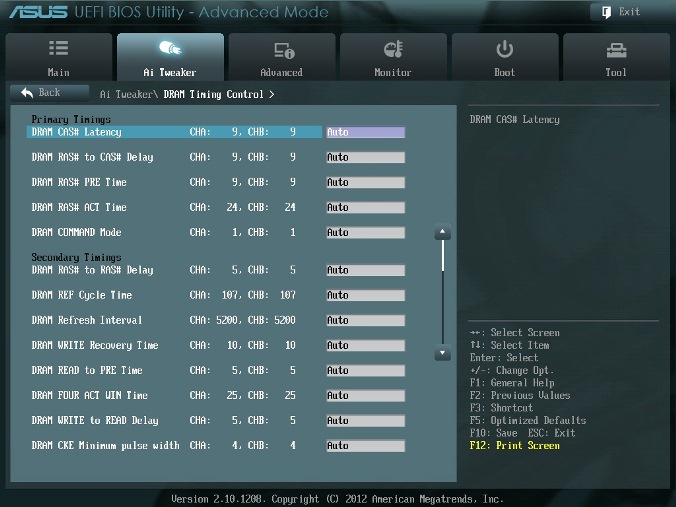
Fig. four.
All these settings should be left equal to the passport values and to Auto if you want to configure the system for reliable operation. Main timings should be set in accordance with SPD memory modules.
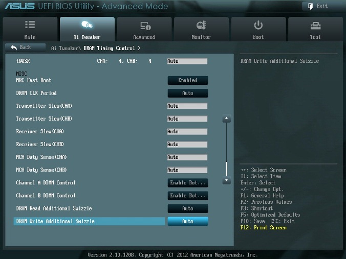
Fig. five
Most of the parameters in Fig. 5 also leave in Auto.
Enable this option (Enabled). This skips the memory test during the system reboot procedure. Download time is reduced.
Note that when using more memory strips and at high frequency of the modules (2133 MHz and above), disabling this setting may increase the stability of the system during acceleration. As soon as we get the desired stability during acceleration, we enable this parameter (Fig. 5).
Determines the delay of the memory controller in conjunction with the attached memory frequency. Setting 5 gives better overall performance, although stability may deteriorate. Install better Auto (Fig. 5).
The window of this menu item is shown in Fig. 6. Here we check the processor multiplier (41 in Fig. 6), be sure to enable (Enabled) the EIST power saving parameter, and also set the threshold powers of the processors if necessary (all the last mentioned parameters are set to Auto (Fig. 6)).
Turning to the menu item Advanced \ ... \ CPU Power Management Configuration (Fig. 2), set the CPU C1E (power saving) parameter to Enabled, and the rest (including parameters from C3, C6) to Auto.

Fig. 6
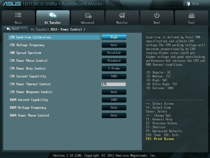
Fig. 7
In fig. 7 shows the recommended parameter values. Some parameters will be considered separately.
The short name of this parameter is LLC. With the rapid transition of the processor to an intensive mode of operation with an increased power consumption, the voltage across it decreases in a jumpwise manner relative to the stationary state. Increased LLC values cause an increase in the processor supply voltage and decrease the processor supply voltage drawdown with an abrupt increase in power consumption. Setting the parameter to high (50%) is considered optimal for 24/7 mode, providing the optimal balance between voltage rise and supply voltage drawdown. Some users prefer to use higher LLC values, although this will affect the drawdown to a lesser extent. Set high (fig. 7).
When this parameter is turned on (Fig. 7), the extended modulation of the VRM signals is turned on to reduce the peak in the spectrum of the emitted noise and pickup in nearby circuits. Enabling this parameter should be used only at passport frequencies, since modulation of signals can degrade the transient response of the power supply and cause instability of the supply voltage. Install Disabled (Fig. 7).
A value of 100% for all these parameters should be sufficient for overclocking processors using conventional cooling methods (Fig. 7).
Fig. eight.
There are two ways to control the voltage of the processor core: Offset Mode (Fig. 8) and Manual. Manual mode provides always unchanging static voltage level on the processor. This mode can be used briefly when testing the processor. Offset Mode allows the processor to adjust the voltage depending on the load and the operating frequency. Offset Mode is preferable for 24/7 systems, as it allows the processor to reduce the supply voltage while the computer is idle, reducing power consumption and core heating.
The supply voltage level will increase with an increase in the multiplication factor (multiplier) for the processor. Therefore, it is best to start with a low multiplication factor of 41x (or 39x) and lifting it one step at a time with a check for stability at each rise.
Set the Offset Mode Sign to “+” and the CPU Offset Voltage to Auto. Load the processor with calculations using the LinX program and check the CPU voltage with CPU-Z. If the voltage level is very high, then you can reduce the voltage by applying a negative bias to the UEFI. For example, if our total supply voltage with a 41x multiplier turned out to be 1.35 V, then we could reduce it to 1.30 V using a negative bias with a value of 0.05 V.
Keep in mind that a decrease of about 0.05 V will also be used for open circuit voltage (with a small load). For example, if, with the default settings, the no-load voltage of the processor (with a multiplier equal to 16x) is 1.05 V, then subtracting 0.05 V will result in approximately 1.0 V of the no-load voltage. Therefore, if you reduce the voltage using too large values of CPU Offset Voltage, a moment will come when the no-load voltage will be so low that it will lead to computer malfunctions.
If for reliability you need to add voltage at full load of the processor, then use the “+” offset and increase the voltage level. Note that the introduced “+” and “-” offsets are not exactly fulfilled by the processor power system. Matching scales are non-linear. This is one of the features of the VID, which is that it allows the processor to request a different voltage depending on the operating frequency, current and temperature. For example, with a positive CPU Offset Voltage of 0.05, the voltage of 1.35 V under load can only increase to 1.375 V.
It follows from the above that for non-extreme acceleration for multipliers that are approximately equal to 41, it is best to set the Offset Mode Sign to “+” and leave the CPU Offset Voltage parameter to Auto. For Ivy Bridge processors, it is expected that most samples will be able to operate at 4.1 GHz frequencies with air cooling.
More overclocking is possible, although with a full CPU load this will lead to a rise in the processor temperature. To control the temperature, run RealTemp.
Set the voltage on the memory modules in accordance with the passport data. This is usually about 1.5 V. The default is Auto (fig. 8).
The parameter sets the voltage for the System Agent. You can leave it on Auto for our overclocking (Fig. 8).
For our acceleration - Auto (Fig. 8). Normal values of the parameter are around 1.8 V. If you increase this voltage, you can increase the processor multiplier and increase the memory frequency above 2200 MHz, since a slight overvoltage relative to the nominal can help system stability.
You can leave the default values (Auto) for slight acceleration (Fig. 8). To date, there has not been a significant connection between this voltage on the chip and other voltages of the motherboard.
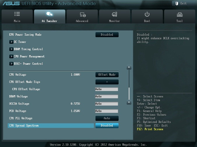
Fig. 9
When this option is enabled (Enabled), the processor core frequency is modulated to reduce the peak value in the spectrum of the emitted noise. It is recommended to set the parameter to Disabled (Fig. 9), since when overclocked, frequency modulation can degrade system stability.
The author thus managed to establish a multiplier of 41, which made it possible to accelerate the simulation using MatLab.
Post cool adopted on the site overclockers. This is understandable, since on this site there are mostly reckless,
AI Overclock Tuner
All actions related to overclocking are performed in the AI Tweaker menu (UEFI Advanced Mode) by setting the AI Overclock Tuner parameter to Manual (Fig. 1).
Fig. one
BCLK / PEG Frequency
The BCLK / PEG Frequency parameter (hereinafter referred to as BCLK) in fig. 1 becomes available when Ai Overclock Tuner \ XMP or Ai Overclock Tuner \ Manual is selected. A BCLK frequency of 100 MHz is the base frequency. The main parameter of overclocking is the frequency of the processor core, obtained by multiplying this frequency by a parameter - a processor multiplier. The final frequency is displayed in the upper left part of the Ai Tweaker window (in Figure 1, it is 4.1 GHz). The BCLK frequency also adjusts the memory frequency, bus speed, and so on.
A possible increase in this parameter during overclocking is not large - most processors allow you to increase this frequency only to 105 MHz. Although there are separate samples of processors and motherboards, for which this value is equal to 107 MHz and more. With careful acceleration, taking into account the fact that in the future additional devices will be installed in the computer, this parameter is recommended to be left at 100 MHz (Fig. 1).
')
ASUS MultiCore Enhancement
When this option is enabled (Enabled in Figure 1), the ASUS policy for Turbo mode is adopted. If the option is disabled, the Intel policy for Turbo mode will be applied. For all configurations during overclocking, it is recommended to enable this parameter (Enabled). Turning this off can be used if you want to run the processor using Intel policies, without overclocking.
Turbo ratio
In the window of Fig. 1 set the Manual mode for this parameter. Turning to the Advanced \ ... \ CPU Power Management Configuration menu (Fig. 2), we set the multiplier 41.
Fig. 2
Go back to the AI Tweaker menu and check the value of the multiplier (Fig. 1).
For very careful users, we can recommend an initial multiplier value of 40 or even 39. The maximum multiplier value for non-extreme acceleration is usually less than 45.
Internal PLL Overvoltage
Increasing (overclocking) the operating voltage for internal phase automatic frequency control (PLL) allows you to increase the operating frequency of the processor core. Selecting Auto will automatically enable this option only when increasing the multiplier of the processor core beyond a certain threshold.
For good samples of processors, this parameter should be left at Auto (Fig. 1) during acceleration up to factor 45 (up to a processor operating frequency of 4.5 GHz).
Note that the stability of the wake-up mode can be affected when this parameter is set to Enabled. If it is detected that your processor will not accelerate to 4.5 GHz without setting this parameter to the Enabled state, but the system is not able to wake up from sleep mode, then the only choice is to operate at a lower frequency with a multiplier less than 45. For extreme Acceleration with multipliers equal to or greater than 45 is recommended to be set to Enabled. With careful acceleration choose Auto. (Fig. 1).
CPU bus speed: DRAM speed ratio mode
This parameter can be left in the Auto state (Fig. 1) in order to apply further changes during overclocking and tuning the memory frequency.
Memory frequency
This parameter is visible in fig. 3. It is used to select the frequency of the memory.
Fig. 3
The Memory Frequency parameter is determined by the BCLK frequency and the CPU bus speed parameter: DRAM speed ratio mode. The memory frequency is displayed and selected in the drop-down list. The set value can be checked in the upper left corner of the Ai Tweaker menu. For example, in fig. 1 we see that the frequency of the memory is 1600 MHz.
Note that Ivy Bridge processors have a wider range of memory frequency settings than the previous generation of Sandy Bridge processors. When overclocking the memory, together with an increase in the frequency of the BCLK, you can make more detailed control of the frequency of the memory bus and get the maximum possible (but possibly unreliable) results during extreme overclocking.
For reliable use of overclocking, it is recommended to raise the frequency of memory sets by no more than 1 step relative to the nameplate. Higher memory speeds provide a slight performance boost in most programs. In addition, system stability at higher memory operating frequencies often cannot be guaranteed for individual programs with intensive processor utilization, as well as when going to sleep and back.
It is also recommended to make a choice in favor of memory kits that are in the list of recommended for the selected processor, if you do not want to spend time setting up a stable system.
The operating frequencies between 2400 MHz and 2600 MHz seem to be optimal in combination with intensive cooling of both processors and memory modules. Higher speeds are also possible due to the reduction of secondary parameters - memory timings.
With careful overclocking, we start with overclocking only the processor. Therefore, at first it is recommended to set the passport value of the memory frequency, for example, for a set of DDR3-1600 MHz memory bars, we set 1600 MHz (Fig. 3).
After overclocking the processor, you can try to raise the memory frequency by 1 step. If errors appear in the stress tests, then you can increase the timings, the supply voltage (for example, by 0.05 V), VCCSA by 0.05 V, but it is better to return to the nominal frequency.
EPU Power Saving Mode
Automatic EPU system developed by ASUS. It regulates the frequency and voltage of computer elements in order to save electricity. This setting can only be enabled on the nameplate operating frequency of the processor. For overclocking, turn off this parameter (Disabled) (fig. 3).
OC Tuner
When selected (OK), a series of stress tests will run during the boot process to automatically overclock the system. The final overclocking will vary depending on the temperature of the system and the set of memory used. It is not recommended to turn on, even if you do not want to manually overclock the system. Do not touch this item or choose cancel (Fig. 3).
DRAM Timing Control
DRAM Timing Control is setting the memory timings (Fig. 4).
Fig. four.
All these settings should be left equal to the passport values and to Auto if you want to configure the system for reliable operation. Main timings should be set in accordance with SPD memory modules.
Fig. five
Most of the parameters in Fig. 5 also leave in Auto.
MRC Fast Boot
Enable this option (Enabled). This skips the memory test during the system reboot procedure. Download time is reduced.
Note that when using more memory strips and at high frequency of the modules (2133 MHz and above), disabling this setting may increase the stability of the system during acceleration. As soon as we get the desired stability during acceleration, we enable this parameter (Fig. 5).
DRAM CLK Period
Determines the delay of the memory controller in conjunction with the attached memory frequency. Setting 5 gives better overall performance, although stability may deteriorate. Install better Auto (Fig. 5).
CPU Power Management
The window of this menu item is shown in Fig. 6. Here we check the processor multiplier (41 in Fig. 6), be sure to enable (Enabled) the EIST power saving parameter, and also set the threshold powers of the processors if necessary (all the last mentioned parameters are set to Auto (Fig. 6)).
Turning to the menu item Advanced \ ... \ CPU Power Management Configuration (Fig. 2), set the CPU C1E (power saving) parameter to Enabled, and the rest (including parameters from C3, C6) to Auto.
Fig. 6
Fig. 7
DIGI + Power Control
In fig. 7 shows the recommended parameter values. Some parameters will be considered separately.
CPU Load-Line Calibration
The short name of this parameter is LLC. With the rapid transition of the processor to an intensive mode of operation with an increased power consumption, the voltage across it decreases in a jumpwise manner relative to the stationary state. Increased LLC values cause an increase in the processor supply voltage and decrease the processor supply voltage drawdown with an abrupt increase in power consumption. Setting the parameter to high (50%) is considered optimal for 24/7 mode, providing the optimal balance between voltage rise and supply voltage drawdown. Some users prefer to use higher LLC values, although this will affect the drawdown to a lesser extent. Set high (fig. 7).
VRM Spread Spectrum
When this parameter is turned on (Fig. 7), the extended modulation of the VRM signals is turned on to reduce the peak in the spectrum of the emitted noise and pickup in nearby circuits. Enabling this parameter should be used only at passport frequencies, since modulation of signals can degrade the transient response of the power supply and cause instability of the supply voltage. Install Disabled (Fig. 7).
Current Capability
A value of 100% for all these parameters should be sufficient for overclocking processors using conventional cooling methods (Fig. 7).
Fig. eight.
CPU Voltage
There are two ways to control the voltage of the processor core: Offset Mode (Fig. 8) and Manual. Manual mode provides always unchanging static voltage level on the processor. This mode can be used briefly when testing the processor. Offset Mode allows the processor to adjust the voltage depending on the load and the operating frequency. Offset Mode is preferable for 24/7 systems, as it allows the processor to reduce the supply voltage while the computer is idle, reducing power consumption and core heating.
The supply voltage level will increase with an increase in the multiplication factor (multiplier) for the processor. Therefore, it is best to start with a low multiplication factor of 41x (or 39x) and lifting it one step at a time with a check for stability at each rise.
Set the Offset Mode Sign to “+” and the CPU Offset Voltage to Auto. Load the processor with calculations using the LinX program and check the CPU voltage with CPU-Z. If the voltage level is very high, then you can reduce the voltage by applying a negative bias to the UEFI. For example, if our total supply voltage with a 41x multiplier turned out to be 1.35 V, then we could reduce it to 1.30 V using a negative bias with a value of 0.05 V.
Keep in mind that a decrease of about 0.05 V will also be used for open circuit voltage (with a small load). For example, if, with the default settings, the no-load voltage of the processor (with a multiplier equal to 16x) is 1.05 V, then subtracting 0.05 V will result in approximately 1.0 V of the no-load voltage. Therefore, if you reduce the voltage using too large values of CPU Offset Voltage, a moment will come when the no-load voltage will be so low that it will lead to computer malfunctions.
If for reliability you need to add voltage at full load of the processor, then use the “+” offset and increase the voltage level. Note that the introduced “+” and “-” offsets are not exactly fulfilled by the processor power system. Matching scales are non-linear. This is one of the features of the VID, which is that it allows the processor to request a different voltage depending on the operating frequency, current and temperature. For example, with a positive CPU Offset Voltage of 0.05, the voltage of 1.35 V under load can only increase to 1.375 V.
It follows from the above that for non-extreme acceleration for multipliers that are approximately equal to 41, it is best to set the Offset Mode Sign to “+” and leave the CPU Offset Voltage parameter to Auto. For Ivy Bridge processors, it is expected that most samples will be able to operate at 4.1 GHz frequencies with air cooling.
More overclocking is possible, although with a full CPU load this will lead to a rise in the processor temperature. To control the temperature, run RealTemp.
DRAM Voltage
Set the voltage on the memory modules in accordance with the passport data. This is usually about 1.5 V. The default is Auto (fig. 8).
VCCSA Voltage
The parameter sets the voltage for the System Agent. You can leave it on Auto for our overclocking (Fig. 8).
CPU PLL Voltage
For our acceleration - Auto (Fig. 8). Normal values of the parameter are around 1.8 V. If you increase this voltage, you can increase the processor multiplier and increase the memory frequency above 2200 MHz, since a slight overvoltage relative to the nominal can help system stability.
PCH Voltage
You can leave the default values (Auto) for slight acceleration (Fig. 8). To date, there has not been a significant connection between this voltage on the chip and other voltages of the motherboard.
Fig. 9
CPU Spread Spectrum
When this option is enabled (Enabled), the processor core frequency is modulated to reduce the peak value in the spectrum of the emitted noise. It is recommended to set the parameter to Disabled (Fig. 9), since when overclocked, frequency modulation can degrade system stability.
The author thus managed to establish a multiplier of 41, which made it possible to accelerate the simulation using MatLab.
Source: https://habr.com/ru/post/185888/
All Articles