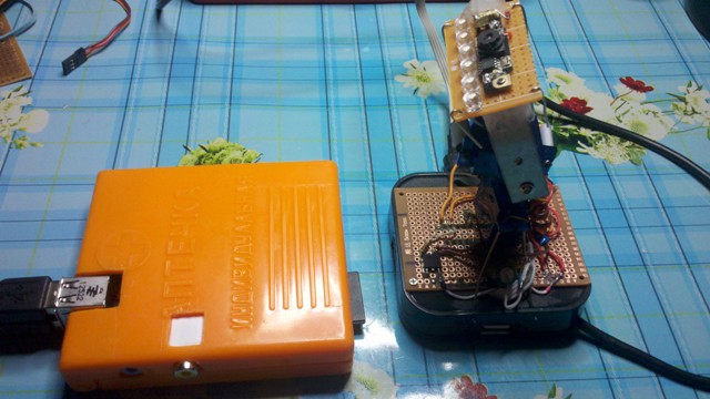
We saw Pan / Tilt webcam (which is spinning) + the ability to connect all sorts of sensors for ~ $ 15

Due to the fact that the previous hack went “into the sunset”, an idea appeared to make an uncomplicated swivel (in two axes - Pan / Tilt) webcam for installing it on the ceiling near the server, which weighs on the wall and eats valuable electricity, around the clock. Let him do something useful.
Flight of fancy in chronological order ....
')
"The simplest seems to you difficult as long as you are afraid."
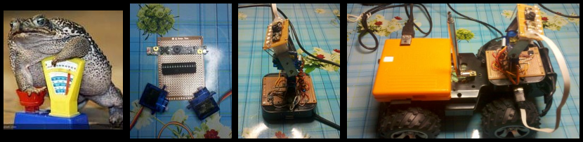
As usual, it all started with laziness. Turning the webcam with your hands turned out to be an extremely difficult task, especially if you need to get out of the chair. A natural question arose - why can't she turn herself? I checked with the calendar - everything is exactly 21st century, I tried to search for ready-made webcams and was impressed with the prices. He began to think what could be so expensive about it, in order to cost such money and did not invent it. (The struggle of laziness with the toad is still a spectacle.) I tried to estimate the budget and it turned out that the thing I needed could be built for a rather ridiculous price and quickly. (It helped that, after previous hobby projects, a lot of information remained where and how much you can afford to get a lot of kits. If you need, I can help anyone with links. Everything was purchased in Ukraine.)
So the idea is simple as mooing - we take an ordinary webcam and glue it to the clever pivotal construction of two servo drives. Servos are controlled using Atmega8 (microcontroller) in which a kind person has already flashed an Arduino bootloader (where to go without it). The microcontroller receives commands from the computer and turns the camera through servo drives. In order not to go through a fascinating quest - “find the COM port on your computer” we connect the microcontroller immediately via USB, but since we are not so steep to upload USB emulation software to the microcontroller right away, we will use a USBtoUART converter based on pl2303 because they are full everywhere and firewood from them, already from the box, there is in everyones there Linux and other hotbeds of dissent.
A small digression before you begin:
1. I always have everything looks so clumsy because I am usually guided by the principle - "let it work at least somehow, but right now, than it is possible never." I have long noticed that if I don’t see the result, I quickly lose interest and the project turns into a burden rather than what I want to do. But if the current project is really useful, you will not get anywhere from gradually doing “refactoring” or whatever it is called in DIY. In general, self-deception is a tricky thing, sometimes it can even be used to advantage.
2. Some photos are borrowed from the immense Internet, therefore, in no case do I pretend to them, but only use them in order to show everything as clearly as possible.
3. And one last thing. Once in middle school, my Russian language teacher frankly said that teaching me literacy is a waste of time (just blunt the pointer). And it was a very wise decision, which I fully support. Therefore, people who, in unequal battles, with a superior enemy, are selflessly fighting for grammar, punctuation and spelling can write to me in a personal note about my ignorant outrages of the great and powerful, I will rule. But I beg you not to divorce hollivary in the comments!
Components:
1. Webcam - $ 4
2. Microcontroller Atmega8 + related - $ 3
3. USB hub - from $ 3
4. Servos - $ 7
5. USBtoUART - 2-3 $
6. Regarding Direct Hands and Pure Mind - alas, but probably priceless.
Naturally, the prices are approximate and strongly depend on your geographic coordinates, the depth of the storage room with its own reserves or the presence of such comrades.
So we start to cook porridge from the ax.
1. Servos.
The servo is able to turn 180 degrees, but actually a little less. (You can see this in the second video when the camera passes 0-> 360 degrees horizontally.) Pick up the servos based on the weight of which you will “turn”. (
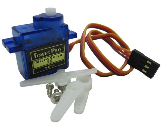
Actually here are these servos for me.
If you install a camera under the ceiling, then two serfs will be able to almost completely block the lower hemisphere (
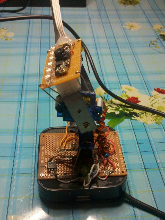
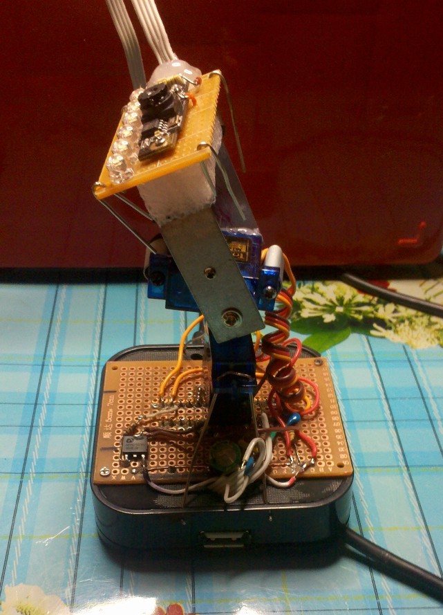
As usual, I wanted everything to move right now, therefore I didn’t master a long thoughtful design, but simply took a broken metal strip (a cap from a standard slot of expansion cards of a PC system unit) and built the minimum required fastening. Then, with the help of the second such plug, I built the part on which the webcam will cling. I think everyone has such stubs and you didn’t sleep at nights from painful obsessive thoughts where to put them.

That's how it looks like. (It looks dumb, but it works.)
2. Webcam.
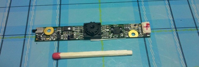
This is a special topic. At first I was thinking of using an ordinary webcam, but then I was visited by a very good idea that later made the budget much easier and simplified the design. The fact of the matter is that once, for the sake of interest, I connected a webcam from a dead laptop to a USB webcam. I looked at the prices of notebook webcams and was quite surprised when it turned out that they were much cheaper than usual. Apparently the whole thing is that this is not a very spare part for a laptop and the prices for them can not be turned up. And they also connect to the PC in no obvious way.
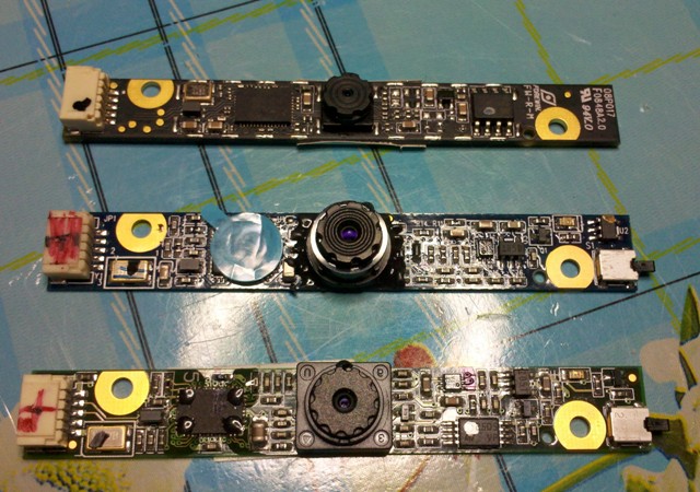
Scatter webcam
I can’t say with full confidence that all notebook cameras are connected via USB, but out of the 4 purchased by me, three were earned at once, and the fourth, apparently tricky by pinout, remained for later. (If anyone possesses info on this topic, he can share it with us.)
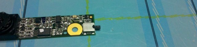
There is still one thing that some cameras seem to be powered not from 5, but from 3.3 volts. I connected them for everyone, one camera worked from 5 volts for at least a year without visible consequences. All the others also worked from 5, but did not have time to check them with time. I simply plugged a diode into the power supply circuit, lowering the voltage in this artisanal way. Pinout webcam laptop below. The land is usually "call" is not a problem and from her already dance.
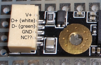
Pinout webcam laptop.
What else is important in the camera used by me was the position sensor and the picture turned itself, it can be done programmatically, but when it works, this in itself pleases it. On the other webcams, there were for this purpose, mechanical flags-switches are provided, it is also easy to use them.
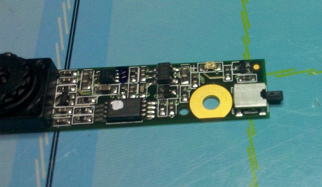
The checkbox switch turns the picture 180 degrees ..
And of course, the size of the webcam itself is a plus. (

The dimensions of the camera.
If you go by using a webcam from a laptop, then I suggest a list of webcams that I used myself and have already checked some moments of compatibility with Linux. This is important if you plan to use mjpeg_streamer in the future. For example, the camera is almost the same as it was used, but the other model (174f: 6 a31) did not want to give out a picture under Linux even when I compiled firewood for it personally. The remaining cameras did not require any dancing with a tambourine.
| - Camera from Acer TravelMate 3020 Series (UVC + JPEG-) P / N: 57.TCYV7.001 USB \ VID_046D & PID_0896 & REV_0100 |
| - Logitech (UVC + JPEG- WIN +) Logitech 1.3 M Acer Aspire 9410 9420 camera Logitech 1.3 M Acer Aspire 9410 9420 TravelMate: 5620 Series P / N: 57.AWZ01.001 USB \ VID_046D & PID_09B0 & REV_0006 & MI_00 |
| - NettopCamera (UVC + JPEG-) 5986: 0241 |
| - Camera from older laptops Asus F8s, F5RL (UVC + JPEG-) 174f: 5a31 This is the camera that I used. |
Decoding notes:
UVC - Does UVC support a specific camera ( Here is a list of UVC cameras)
JPEG - does hardware compression from webcam support
WIN - whether the camera starts itself in Windows 7 (so that it does not hunt for firewood itself)
It is natural that cameras for laptops will most likely be sold only with an indication of the laptop model and that's it. Therefore, I chose the cameras as follows - “google” for what webcam installed in a particular laptop and tried to find information about compatibility with Linux. Most of the information can be found in the driver section on the website of the laptop manufacturer. And under Windows, firewood is usually not a problem. It was important for me to have specific webcam drivers in modern Linux kernels.
3. Converter USB to UART.
Now ready-made converter modules are being sold, on the one hand USB, and on the other, the UART comb. They are made on different microcircuits, but the best thing is to have a microcircuit in it, and not the Chinese “dead bug-epoxy” (dead bug) that you could see in almost any cheap electronics. The cheapest pl2303 chip comes across. But here, too, there is a trick - for example, the cable for Samsung C100 or Siemens C55 is the same converters, but cheaper and they often cost pl2303. Nokia's famous DCU-5 type cables can also be used, but they are more well known and their prices are higher.
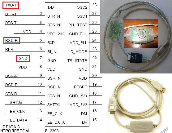
This is what ordinary telephone laces look like which we are interested in. And pinout chip pl2303

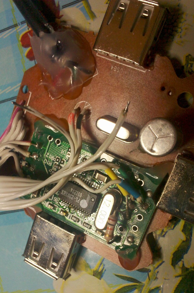
Typical board extracted from such a lace

But these boards are sold separately.
Actually probably any cable for the phone that does not have a USB output, but which, nevertheless, it connects to a PC via USB is a similar converter. Drivers for all more or less well-known chips are usually already there in almost all modern operating systems. If you have connected a converter and you have a port in the COM system, then there is a driver. Next, you can close the contacts RX and TX and try to transmit something in the usual Termenal. If the answer comes, what is sent means everything works and you can move on. You can use the hercules program, found it by chance, turned out to be very useful, although it was designed for something completely different.
If you have a choice, it is better to stop at the telephone cable whose converter board is located in the middle and can be easily removed. Further it will be clear why. You also need to note that the light wedge did not converge on pl2303 and there are adapters for example on FTDI or CP2101 microcircuits, but they are more expensive and more serious, it is better to save them for other applications.
4. USB hub.
You might think - why is he here? Everything is simple - we can very easily be able to organize the connection of the final camera to the PC using just one cable instead of several, and there will be free ports on the hub, you can connect anything there. Need a cheap hub, but guaranteed version 2.0. Therefore it is better to test it. This can be done, for example, by copying files from a USB flash drive and by speed of copying you can determine the version of the hub or connect a webcam. You can of course look in the device manager, but the cunning Chinese can disguise everything there. I took one of the most common hubs and for one I used it as a basis for mounting the servos topped with a camera. (From the hub itself, four excellent blue LEDs and a mirrored surface were extracted, which he no longer needs.)

Hub
They forgot to install capacitors in it, although the places for them are clearly distinguishable, and since we have servo drives and they will most likely work and drain the voltage better than capacitors. I think any suitable with a working voltage> = 6 volts. Strongly gigantic in capacity do not put, I suspect that the USB controller of the mother may decide that a short circuit occurred at the time of charging a large capacity with a large current and send you far away with your DIY.
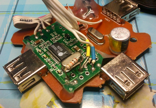
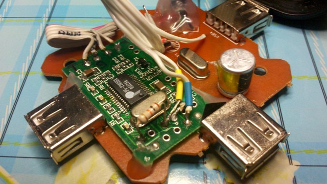
Hub already with a capacitor and pl2303
Most likely you will get a hub on the FE1.1s microcircuit. It seems to be a normal microcircuit, but I had a sad experience with it. I expanded the number of USB ports on the Raspberry Pi rev.A and for a long time could not understand why the raspberry constantly hangs, then it turned out that the hub is hanging. Therefore, before you use a specific hub, you will overtake 10-20 gigabytes continuously through it to make sure that a particular instance works stably. If not, you can try to lower the supply voltage from 5 to 3.3 Volts, I have got such a number.
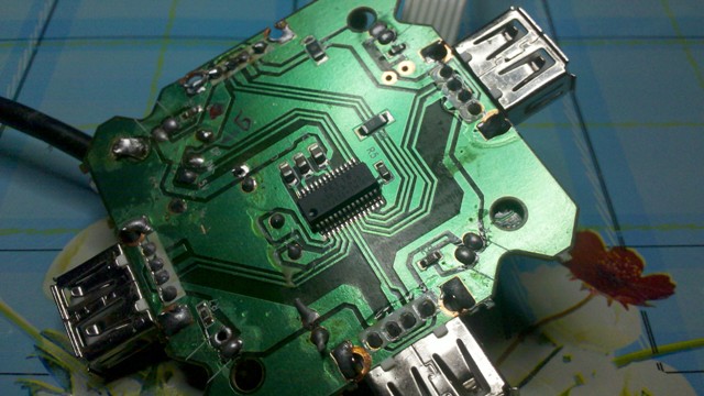
Chip FE1.1s.
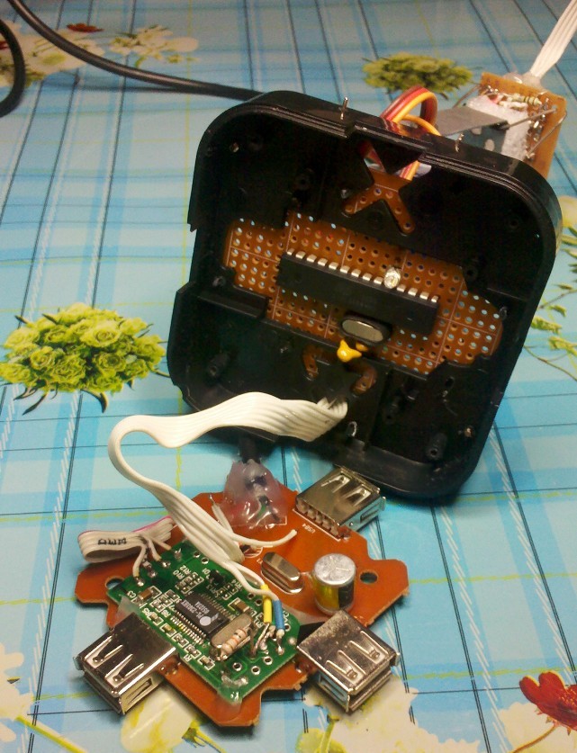
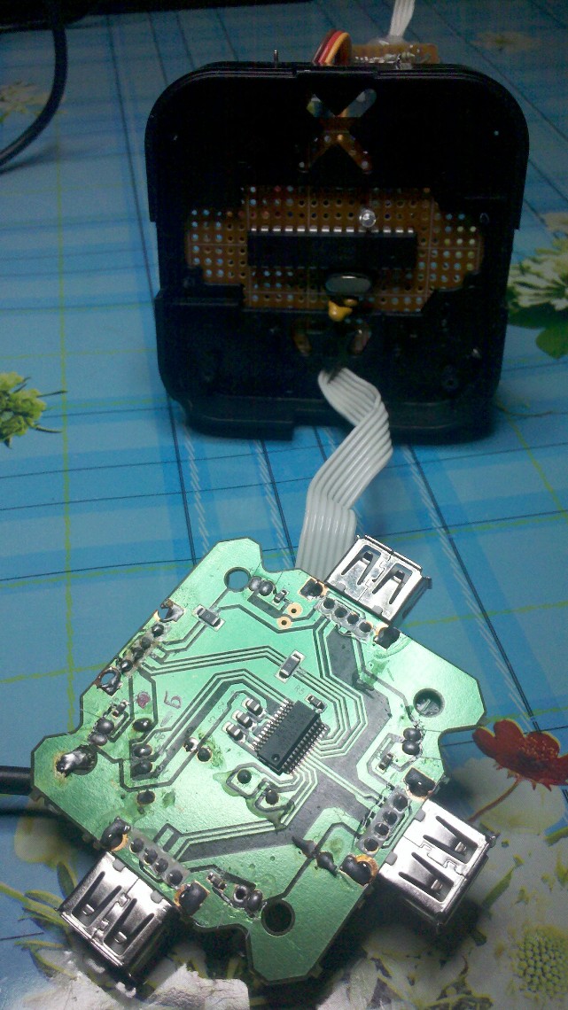
We solder a USBtoUART converter to one of the hub ports, responsibly solder the USB mother socket, so that then we don’t accidentally connect another device there. Next, the converter can be hidden in the housing of the hub, and only three wires RX, TX and DTR can be brought outside. From the hub board itself, you can also remove two power wires, which we then solder to the board with a microcontroller.
5. Microcontroller.
This is the most voluminous area of work, but interesting. If you do not want to be soared with the converter and the connection of the microcontroller itself, then of course you can take one of their ready-made Micro Arduino boards immediately with a USB output, but you know that it will be more expensive. And it's a pity to bury such a board forever in the hub.
Probably not everyone knows that if we take, say, an Atmega8 minimum microcontroller with an Arduino bootloader, then using just a couple of pieces of wire, a capacitor and a power source, we get a strange design that will still be stitched with sketches and the diode will flash (if you solder it of course). That is, get a super-cheap, ultra-lightweight Arduino.
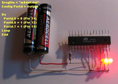
Minimum Arduino of Atmega8
The photo specifically led for those who are afraid to start, thinking that microcontrollers are difficult. Excessive congestion of manuals often scares a person and does not allow him to decide to start doing something. Sometimes it is very useful to omit some moments and just show the person the shortest way. Features he will master in the course of the play.
He himself repeatedly passed this way and now if the instruction is very “extensive” I immediately look for something for dummies. (In this moment, perhaps the most basic minus of our education lies.)
Dear author of the whole trainer, please understand one simple thing - a person who learns something, as it were, learns precisely because he does not know it yet. It is necessary to try everything to submit MAXIMALLY simply, not to rely on the fact that students of the type should have some kind of “spherical in a vacuum” basic knowledge.“The highest degree of respect for readers is to consider them idiots.”
Once this quote zaminusovali. It should be understood that it means not that readers are idiots. It means that if you can teach an idiot with your manual, then the goal is achieved.
How in the microcontroller to place the Arduino loader I will not be considered in this article, but I want to note that it is not difficult at all and is done with a minimum of equipment (the presence of an LPT port). But then this approach will always pay off. Google to help you.
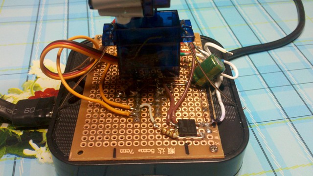
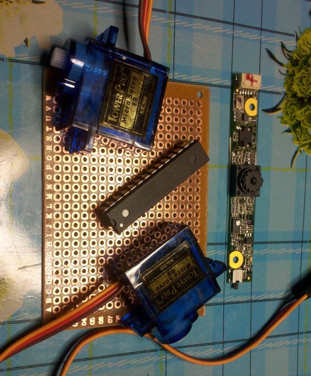
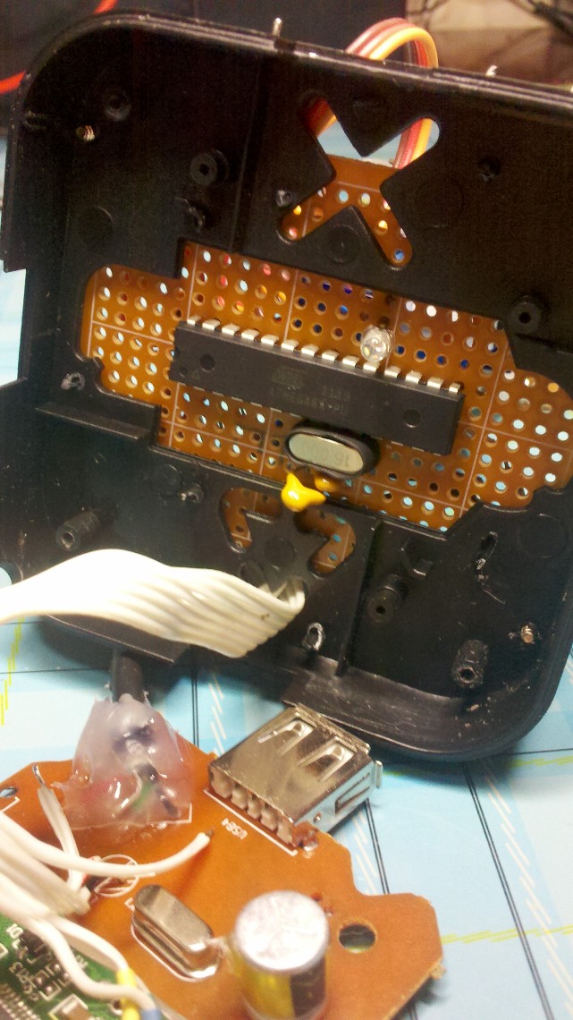
In general, we have an Atmega8 with an Arduino bootloader stitched. Now he is able to sketch and all the work to the microcontroller is reduced to writing fashionable Arduino sketches. At the microcontroller, we use only two outputs, and you can use everything else at your discretion. Hanging up our camera with sensors is now no problem at all. For ease of installation, it is best to take a mock-up board with holes and firmly solder the microcontroller there (it is possible and not tightly, but in a civilized way if you use the dip socket).
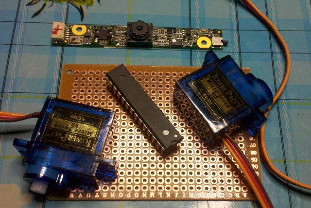
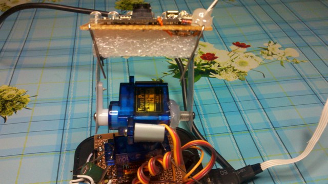
There is still a naked breadboard, microcontroller, camera and servos.
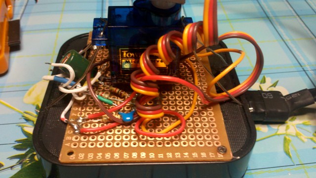
Since the servos are controlled by a signal whose form changes over time and this is the time the microcontroller needs to be adequately “felt”, we still need quartz. In general, we dissolve the power supply and quartz, as well as connect the USBtoUART converter to the microcontroller according to the proposed scheme. Do not forget that when you turn the microcontroller in space, the assignment of the outputs also turns over, in soldering, be guided by the first output that is usually marked. (Again, I don’t consider everyone to be idiots, but I personally managed to get tired of this easily and more than once. I
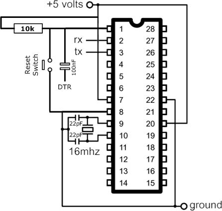
Wiring diagram of power, quartz and reset.
To terminals RX, TX and DTR we solder our interface converter USBtoUART. DTR is connected to the reset pin of the microcontroller (reset) through a capacitor in order for the sketches to be poured automatically without having to press reset.
If everything is connected correctly then you can already connect the microcontroller to the PC and upload the sketch to it. (Strangely enough, the capacitors that stand after quartz interfered with the normal operation of the microcontroller, so I removed them.)
Please note that the sketch is written with the expectation that the camera will be installed on the ceiling. If you intend to install as in the video, then simply reassign the variable buttons.
The sketch itself.
#include "Servo.h" Servo servo1,servo2; int press_xdown= 0x61; // 'a' int press_xup = 0x64; // 'd' int press_yup = 0x77; // 'w' int press_ydown = 0x73; // 's' int light = 0x6C; // 'l' boolean laight = 0; int chassis_light = 13; // int ServoPower = 11; // // ( ) int incomingByte = 0; // int X = 90; int Y = 90; int step = 5; int xmax = 180; int xmin = 0; int ymax = 180; int ymin = 0; unsigned long time_servo; // void setup() { Serial.begin(9600); servo1.attach(10); servo2.attach(9); pinMode(chassis_light, OUTPUT); pinMode(ServoPower, OUTPUT); } void loop() { if (Serial.available() > 0) // { incomingByte = Serial.read(); time_servo = millis(); digitalWrite(ServoPower, HIGH); Serial.flush(); } if ((millis()- time_servo)> 2000 ) // . digitalWrite(ServoPower, LOW); // //------------------------------------------------------ if(incomingByte == press_xup) if(X <=(xmax-step)) X = X + step; if(incomingByte == press_xdown) if(X >=(xmin+step)) X = X - step; if(incomingByte == press_yup) if(Y <=(ymax-step)) Y = Y + step; if(incomingByte == press_ydown) if(Y >=(ymin+step)) Y = Y - step; if(incomingByte>0) { servo1.write(Y); servo2.write(X); Serial.print(X,DEC); Serial.print(":"); Serial.println(Y,DEC); } incomingByte = 0; } The second version of the sketch. Now the camera can move horizontally 360 degrees, and vertically 90 degrees. This is done to simplify remote control. How exactly this happens, look at the second video.
Sketch more difficult.
#include "Servo.h" Servo servo1,servo2; int press_xdown= 0x61; // 'a' int press_xup = 0x64; // 'd' int press_ydown = 0x77; // 'w' int press_yup = 0x73; // 's' int light = 0x6C; // 'l' boolean laight = 0; int chassis_light = 13; // int ServoPower = 11; // // ( ) int incomingByte = 0; // int X = 90; int Y = 90; int step = 5; int xmax = 360; int xmin = 0; int ymax = 90; int ymin = 0; unsigned long time_servo; // void setup() { Serial.begin(9600); servo1.attach(10); servo2.attach(9); pinMode(chassis_light, OUTPUT); pinMode(ServoPower, OUTPUT); } void loop() { if (Serial.available() > 0) { // incomingByte = Serial.read(); time_servo = millis(); digitalWrite(ServoPower, HIGH); Serial.flush(); } if ((millis()- time_servo)> 1000 ) // . digitalWrite(ServoPower, LOW);// //------------------------------------------------------ if(incomingByte == press_xup) { X = X + step; if(X>360) X = 0; } if(incomingByte == press_xdown) { X = X - step; if(X <0) X = 360; } if(incomingByte == press_yup) if(Y <=(ymax-step)) Y = Y + step; if(incomingByte == press_ydown) if(Y >=(ymin+step)) Y = Y - step; if(incomingByte>0) { if(X>180) { servo1.write(180-Y); servo2.write((180-X)*-1); } else { servo1.write(Y); servo2.write(X); } Serial.print(X,DEC); Serial.print(":"); Serial.println(Y,DEC); } incomingByte = 0; } At 15, 16 pin (or 9,10 on Arduino pinout), the signal contacts of the servos are connected, and the power of the servos is connected to the common power. (I know that it is necessary to distribute the power of logic and the power unit, but I decided to do a little bit more, I will probably be punished for it with severe glitches in the future.)
You can rotate the camera using the well-known key combination a, s, d, w. Naturally, the codes of these keys must be sent to the COM port (which appears when a USBtoUART converter is plugged into the PC) on which the microcontroller hangs.
For the very lazy (like me), I sketched a simple program to turn the camera around with a PC . Source there. You can watch the video either via Skype or via VirtualDub, but in general there are enough ways.
6. Light (optional).
The camera from the laptop is very miniature on the breadboard where it is located there are a lot of places where the LEDs were immediately soldered and the CMOS transistor connected to the power supply. I connected the voltage from the micro-diode to the camera itself to the gate of the transistor. Now when the camera is activated, the mini searchlight is automatically cut. Here is a link to how you can play with CMOS transistors on the subject of commuting serious loads from the highly respected dihalt . By the way, one of my favorite sites, there is a lot for dummies in electronics, like me.
This is how you can add LEDs to taste.
7. Hub cable gain (optional).
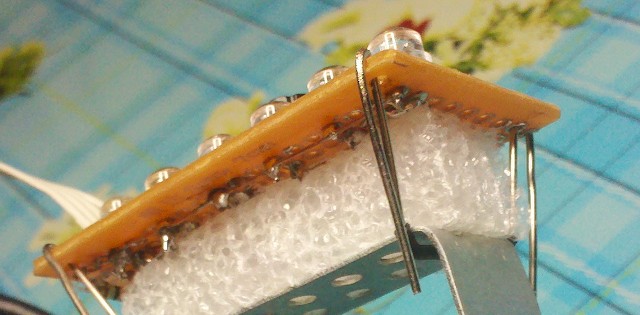
Since we hubbed the hub very much (I am sure he is in shock), the current consumption has increased. For all this garden + light, I no longer had the standard 500 mA from one USB. Therefore, I advise you to replace the hub cable with a better one with a split USB plug at the end. Or to solder the second plug by yourself, using only the power contacts (red and black). This can be done if, close to the plug, carefully remove the sheath and solder another plug to the power wires (only red and black !!!). Do this carefully because burning the USB controller of the mother closes it once. Well isolate everything.
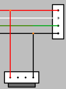
Schematically showed how to strengthen the cable.
You can also add a standard molex connector instead of a second USB plug and thereby get “unlimited” (almost) power, but you won't connect such a design to a laptop.
8. Economical savings (optional).
In order not to power the servos at rest, their power can be turned off using the same method as for turning off the lights. In the sketch, this option is provided. If the commands do not arrive for two seconds, the power of the servos is turned off. Another such trick will get rid of servious jarring serv in idle. This is due to the design features of low-cost servo drives.
I didn’t intend to write so much at all, but it did.
It is clear that all the above written you just scrolled to get immediately to the video and pictures. And they are here!)
Video:
At the request of the workers in a short time he tried to depict a video in which you can evaluate the smoothness of the image from the camera itself.
The servo step is 1, at first the command is given once every 50ms, then once every 100ms.
And step 5, commands every 100ms.
Pictures:
Long diaper with photos, traffic!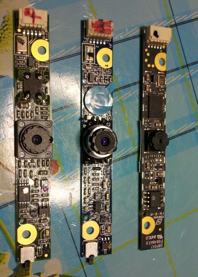

PS
1. If someone tells me how to center the pictures in the article, I will be grateful. With a swoop, something did not work, but it does not look very good.
Source: https://habr.com/ru/post/185604/
All Articles