Home mini climate control do-it-yourself
Good day, dear habrovchane. I want to share my little experience in creating a home climate control with a web-based informer based on an Arduino board using TSOP, IR, DHT22 and Electrolux floor-standing air conditioners and some other components.

So, if you are interested in my implementation, welcome to Habrakat (ready to fill the sketch in the same place).
')
On the eve of the summer, I thought about the need to purchase an air conditioner, but since the layout of the house and apartment does not allow the use of a split system, I had to take a floor air conditioner. Yes, I understood that there would be hemorrhoids with a tube output, so in the introduction I will briefly talk about tuning the air conditioner ligament and my window. Everything is quite simple, there are 2 tubes, one pulls the air, the second takes it outside (hot). Cold air comes out of the central part of the air conditioner.
In order to bring the tube I needed:
• Plexiglas the size of 1 casement of my window (double-glazed windows) plus openings for pipes.
• 4 mounts for plexiglass installation
• tube for air vent (picked up foil) 2 pcs.
• air conditioning
The bottom line is that in Plexiglas there are 2 holes for our tubes, which take in and out the air. This was done to prevent air sparseness (I read about it in different forums, but did not notice it myself, but I won’t be any worse). I fixed the tube with the output of hot air in our plexiglass at a slight angle up and to the left, the tube of the air intake at a slight angle down and to the right so that the air flows do not intersect. The plexiglass mounts were made outside the window, the idea for this was looking at the installed mosquito net in the next window section (living on the lower floors bore mosquitoes, plus during the flowering of the poplars my grid became terry, but the fluff did not fall into the apartment).
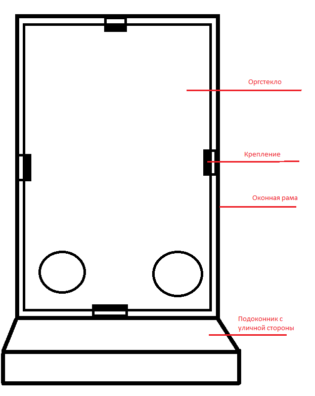
The picture above seems to understand how it is attached, where the tubes are located, etc. If you have questions, ask in the comments. And so, now we have an air conditioner, which is located near the window, tubes are inserted into Plexiglas from the air conditioner and brought out to the street (the only inconvenience is that the window is constantly open, but it is blocked by plexiglass, not aesthetically pleasing, but to drill the supporting wall, holes in diameter ~ 20cm 2 pieces on the street there is no desire). We now turn to the logic of our system.

In my case, the air conditioner is Electrolux EACM-14EZ / N3, which has several modes + IR remote control. The first and main one is, of course, cooling (hi, Cap). The second, but no less useful, is the dehumidification of air (not humidification, namely dehumidification). The second is very useful, especially in the heat, because the heat is easier to carry in the drier air (as well as cold), and recently I had a humidity of 75-80% in the apartment (at least I was told by a hygrometer donated at work ). To humidify the air, I use a cheap humidifier, which simply heats the water to the boiling point and that's it, the connection description is not there yet, because I have not completed it yet, but I will publish it, the fact is that it does not have any IR type interfaces, etc. , therefore it is necessary to disassemble it, solder your controller with a relay, but let us return to the main topic. For me and my wife, the temperature in the room is ideally 22-24 degrees (well, in extreme cases, 25 but with sufficiently low humidity).

Therefore, we highlight the following logic:
• Turn on the cooling system in case of t> 25 degrees
• Turn off the cooling system at t <22 degrees
• Turn on the dehumidification mode when h> 60%
• Turn off the dehumidification mode when h <40%
• If 22 <t <25 and 40 <h <60 - we turn on the automatic mode (the condo alternately turns on dehumidification and cooling itself, or we manage the shift through the controller, for example, for 5 minutes of each type)
In total, we have 4 IR teams:
• Turn on the condo for maximum cooling (fan for maximum, temperature 16 or 18 degrees depending on the model)
• Switch on the condo for maximum drainage (fan for maximum)
• Enable condo in automatic mode.
• Turn off the condo
It seems to be understandable here. Personally, I chose for myself the option with 4 teams, when in the case of the intersection of the rules, just an automatic mode is turned on (you can of course write your alternate switching system, but for now, that’s enough for me).
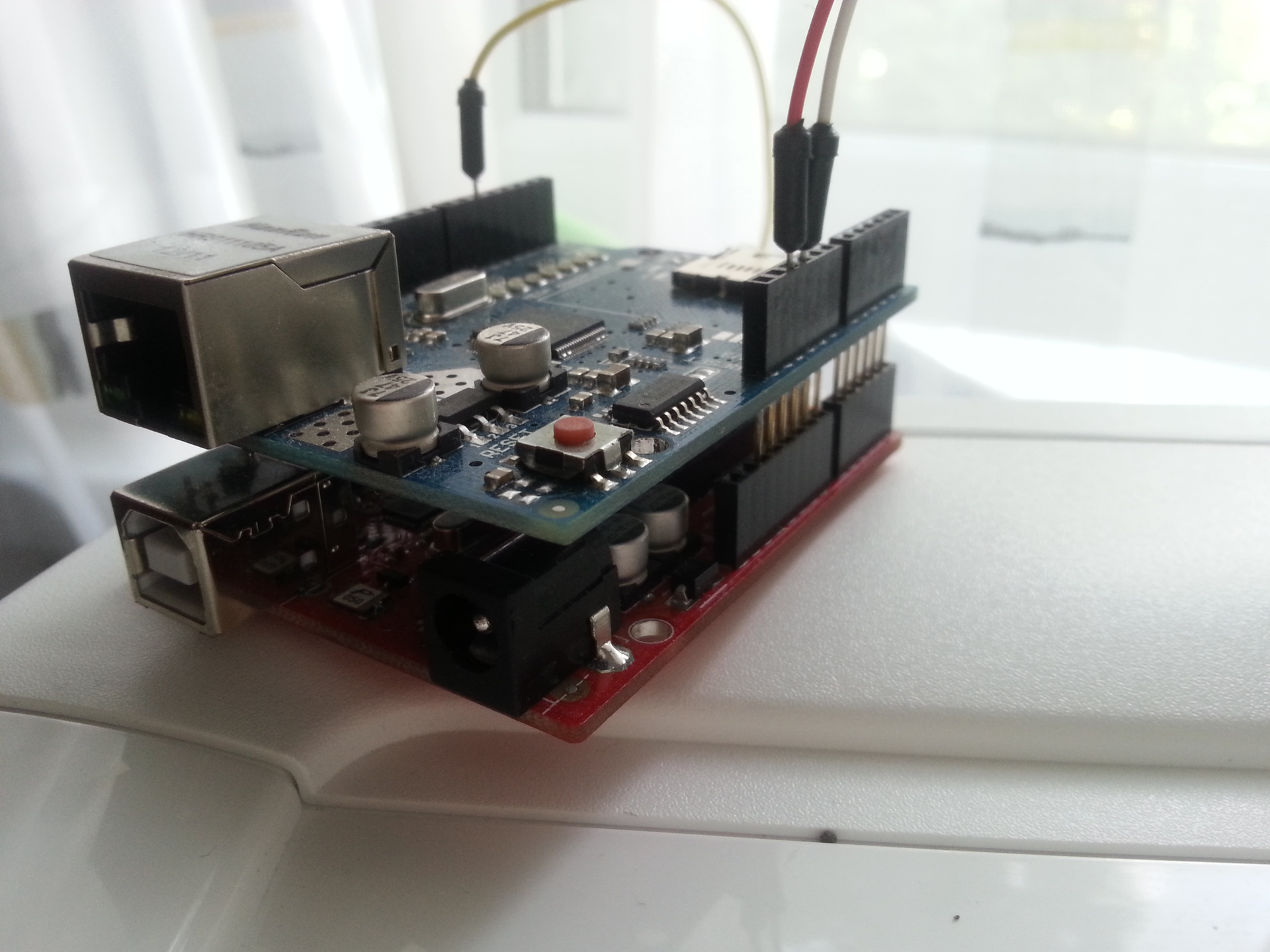
Our arduino with an ethernet shield in the collection.
We write the command console air conditioner. For this, I used the ready-made library for arduino, the PSTN connected to it and the remote from kondeya itself. We download the library from the githab (by the way, the last version solved the problem with the long package, it was increased to 100, before that some teams did not fit, because there was a limit of 50, and often met a lot of angry reviews, although it was fixed in 2 seconds). The advantage of this library is that there is a rather convenient logger of incoming signals to our PSTN in the demo and this is in Serial.

Here is the TSOP and the IR LED in front of it.
Pinout TSOP22 (for most others, as far as I know, everything is identical):

Both raw data (that is, not processed) and ready-made packet packets by type (for example, NEC, RC5, etc.) are displayed if they are determined, which can be sent directly from the library in a short form. My air conditioner does not have a generally accepted standard of packages (by the way, like the TV, but the console from online using the NEC protocol), so we will use the so-called raw data. First, we connect our PSTN sensor as shown in the picture below (ignore the LED) and fill in our Parser firmware from the Arduino demo library (IRrecvDump).
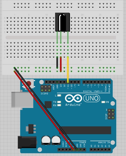
TSOP wiring diagram
The first time I had a bug: the packages went on their own. He did this in the room and suggested that something could fonit. Came out with a laptop on the balcony - the background continued. Honestly, I didn’t understand what the problem was, but I went to the nearest electronics store and bought 2 new vehicles (the first one was buggy, was sent from China), having connected such a glitch and the packages were displayed only when the button was pressed on the remote. To record the signal, we connect the arduino to the computer, after connecting everything in the picture above, open the port monitor, specifying the required com port. We bring the remote and press the button with the desired command. The monitor displays all the necessary information. I used custom firmware to immediately generate code that would be more convenient for copy-paste to insert into the sketch, nothing complicated, but since formatted hard, forgot to save this sketch. The demo from the library is more than enough and not much different.
As a result, we received packages for sending, for example, to turn on the air conditioner for a maximum of me:
Regarding the Raw periods - where the "+" is where we burn the specified number of microseconds, where the "-" we do not burn the specified number of microseconds. For those who will, for example, use AVR type controllers, there is a delay function with microseconds indicated. Used approximately like this:
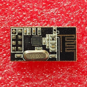
Thus we collect all the necessary commands. Now we connect our DHT22 to the Arduino, IR LED and write our sketch that carries the main logic. In this version, I, unfortunately, use a fully wired data transmission system, I ordered the NF24L01 sensors, but how many they still will come from your favorite China is unknown, for more details see the list of what is planned to be improved in the last part of the article in the TODO section. Also for the implementation of the project, Ethernet Shield was used (a counterpart from the Middle Kingdom in the region of 9-15 dollars (I took 9)).
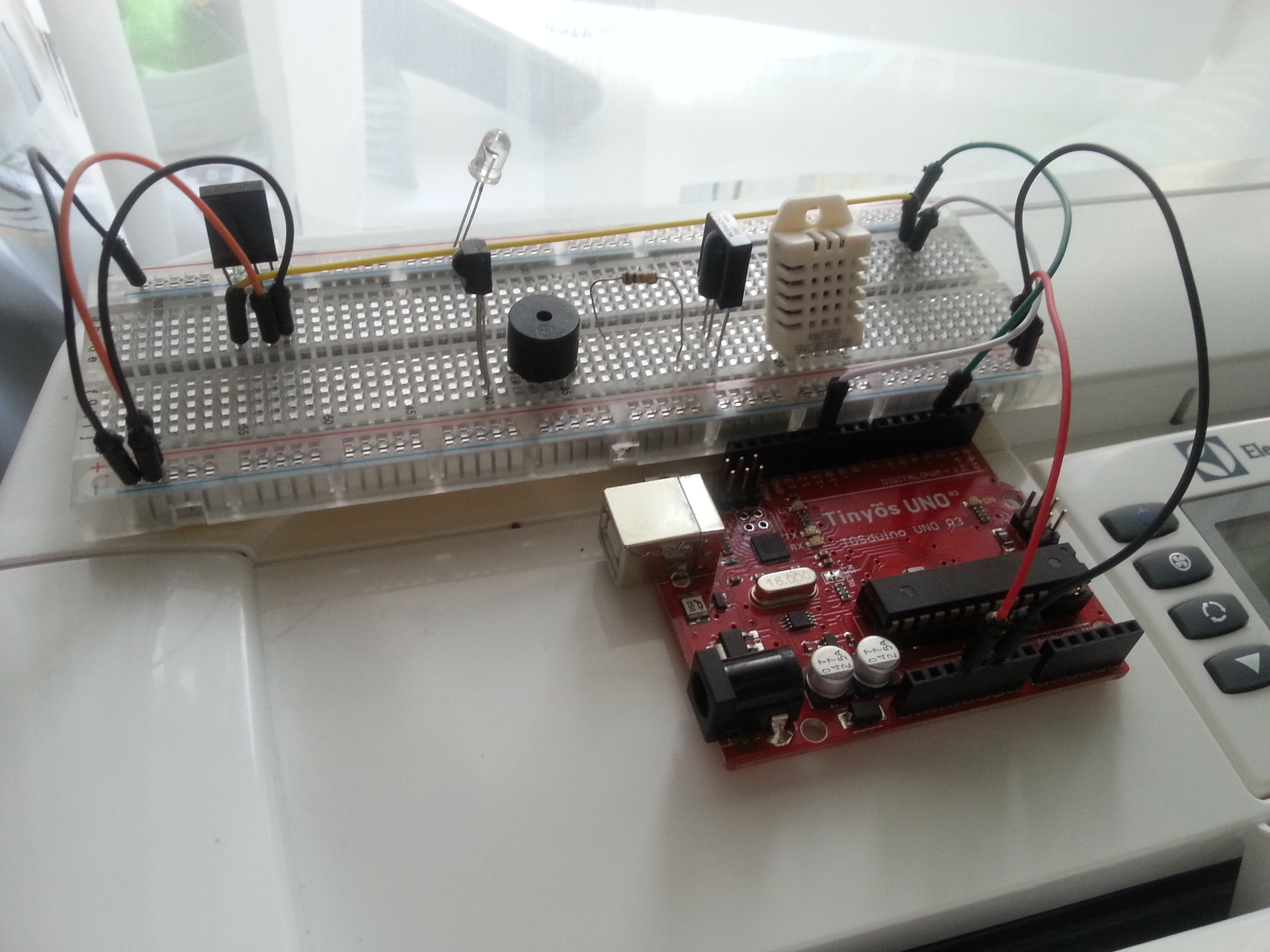
In the photo debug temperature sensor
As a result of the collection we will have the following scheme:
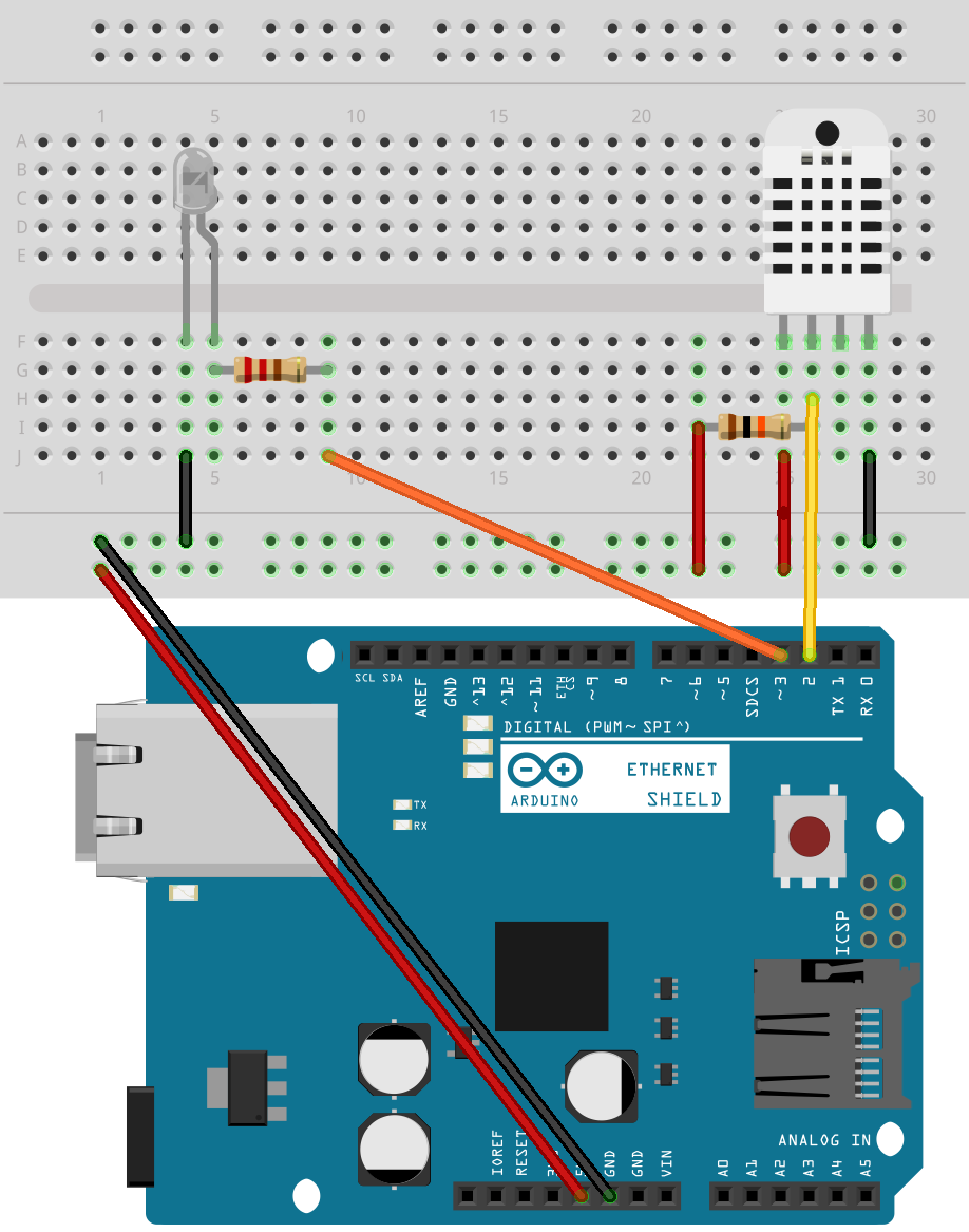
Some people recommend placing a pull-up pull-up resistor of 10 kΩ between the Vcc and Data pins, but it works without it, and I don’t see any real sense, to be honest, they don’t cause any measurement.
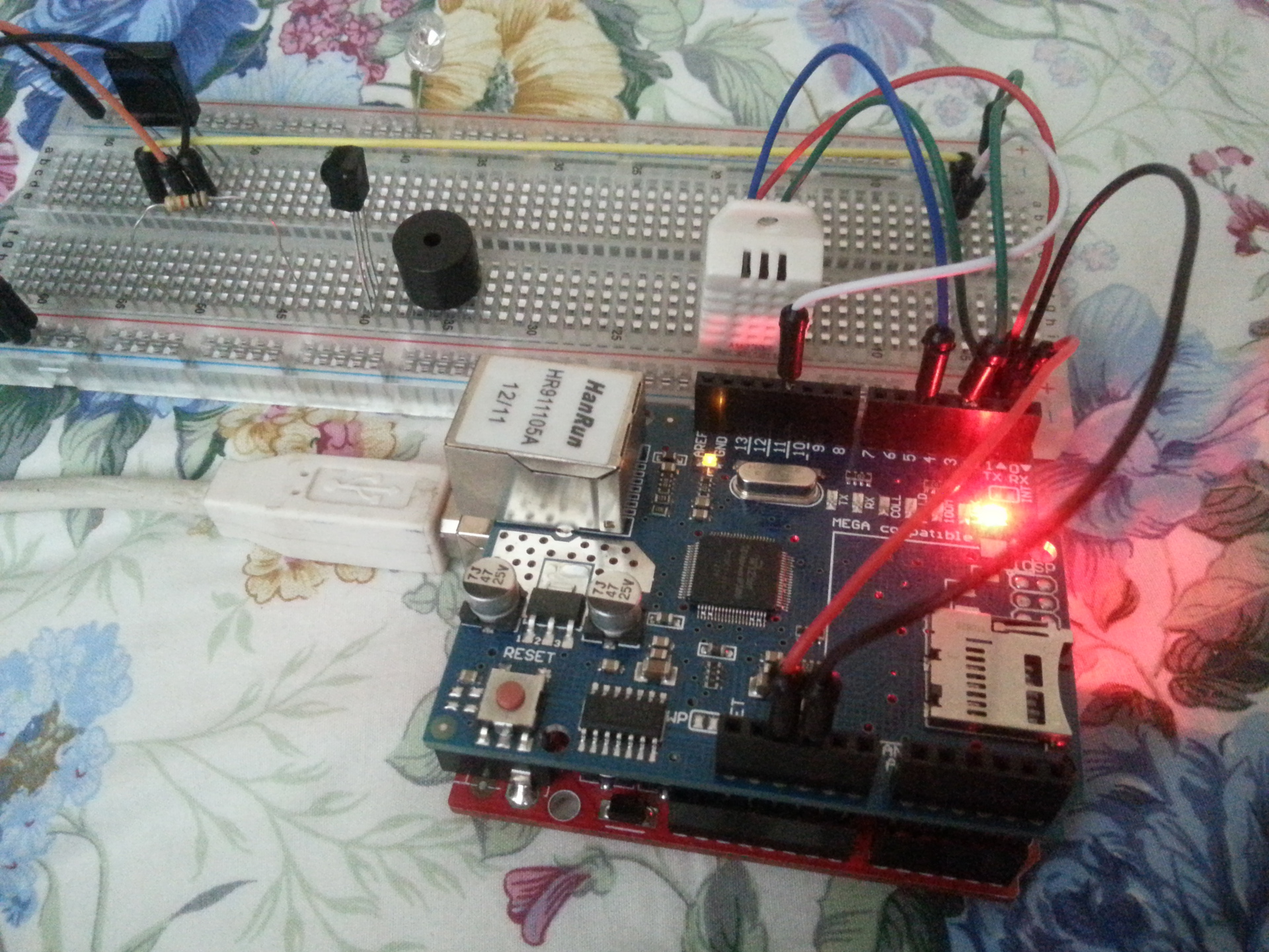
The entire system is assembled during testing.
Our DHT22 is connected to 2 analog pins, IR LED to 3 (the one with pwm).
This code looks at the temperature sensor, sends data to my server (also sends the latest status of the air conditioner until it is processed, but may be useful), also the WorkWithCondey function is called which checks the sensor data and decides whether or not the condo is turned on and which mode. On the server side, I have a simple php script that accepts a get request with data (only from local ips from the allowed list). He saves this data to the database (while mongodb), and writes the data to a file, this file is available on the Internet, and I wrote a small C # program that reads this data and outputs it in On Screen Display (OSD) mode, i.e. text on top of all windows with no background. What I plan to optimize in this whole scheme, see the section here. If you use my code, do not forget to replace myserver.ru with your data.
Information after casting the sketch:
As can be seen from the log, we have the status of the air conditioner "4". If you look at the source code, then under status 4, the automatic conditioner conditioner condition works for us, which is understandable, because the humidity according to logs is 67.2% and the temperature is 26.4 degrees. If you bring the sensor to the airflow of the air conditioner, the status changes to 0, i.e. air conditioner is disabled.
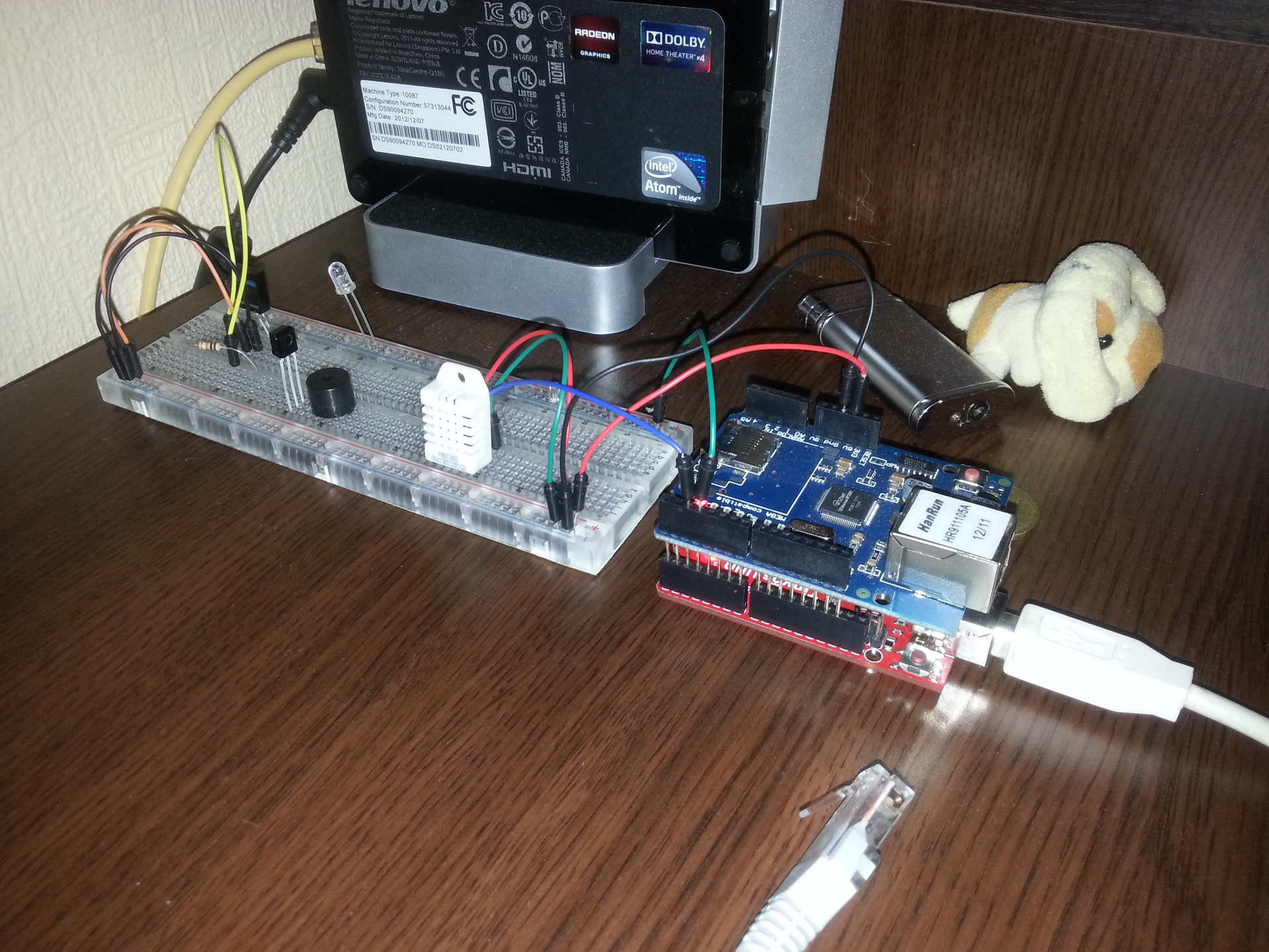
The entire system is assembled on the shelf from where it controls the air conditioner.
We have arduino, ethernet shield, ir led, tsop sensor, air conditioning - and it all works automatically. While I was experiencing it for 2 days (at the weekend), several bugs in the sketch were fixed, it seems there are no failures yet.
So, the list of what is planned to be implemented:
1. Change the data file to Memcache, so as not to torment the file system. Keep the last 5 entries in the memcache just in case
2. Change the database from MongoDB to Mysql (or something else, there is simply no point in the monge, it stood, but there were no other bases, and it was too lazy to bet)
3. To write to the database to use the queue (or Apache MQ or other analogues).
4. Divide the system into 3 parts: arduino with ezernt and RL24L01, board with temperature sensor (2313 tyinka) and RF24L01, infrared LED board (2313) and RF24L01. This is necessary to reduce the size, so that it is unnecessary to connect everything only to the Arduine, and work through the air.
5. Come up with another air exchange, but so far there is not even thought how to do it better (advise in the comments, I will be very happy).
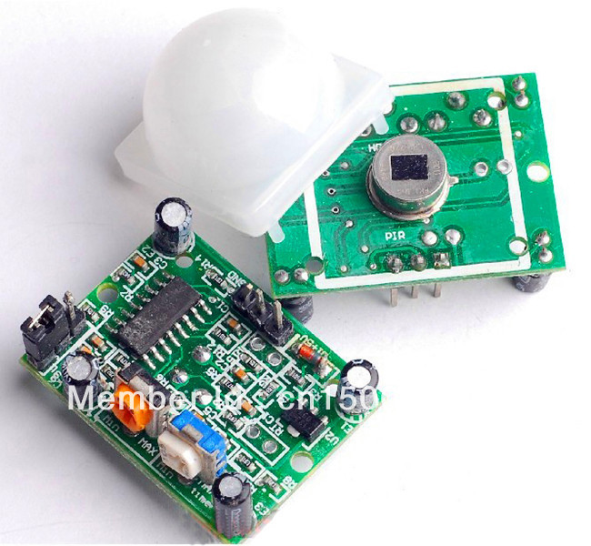
6. In connection with the birth of the child (he was only one month old) I ordered a feast sensors (Ik presence sensor), I do not know how well it will work. When a child (well, in general when finding a person in the room) you need not to include a condo. Plus, the corresponding status will be sent to the script that people are in the room.
7. Modify a cheap humidifier so that it can be connected to this system. There will go the board with NF24L01, 2313 mink and a simple relay. Since This humidifier has only two modes: On and Off, and then from the button :)
NF24L01:
PIR Sensor:
Habra - for the platform, where I can share my personal experience, and add knowledge
DIHALT - for interesting articles, thanks to which I joined DIY
arduino playground - for the library to work with DHT sensors
shirriff - for the library for working with IR signals
China - for cheap components and sensors
You, dear reader, for what I read to the end :)
And of course, my wife for a son and a magic kick in the ass for the realization of this idea.
My sketch above (just in case)
Library for DHT22 (Arduino site)
Datasheet on dht22
Datasheet on TSOP31256 which i use
Library for working with IR (github)
Upd. Added photos, added and updated connection diagrams. Added datasheet. Updated sketch code (small fix). Corrected a link to the library DHT22 & DHT11.
Upd. 2 - Updated the final arduino connection scheme. (Resistors added, thanks for the Siorinex hint)
I hope you liked the article, leave feedback and suggestions in the comments. I will be glad to constructive criticism. And I agree right away, an article for newbies from a newbie in this business. On the weekend I will shoot a video of how it all works with a full description and demonstration.
So, if you are interested in my implementation, welcome to Habrakat (ready to fill the sketch in the same place).
')
Introduction.
On the eve of the summer, I thought about the need to purchase an air conditioner, but since the layout of the house and apartment does not allow the use of a split system, I had to take a floor air conditioner. Yes, I understood that there would be hemorrhoids with a tube output, so in the introduction I will briefly talk about tuning the air conditioner ligament and my window. Everything is quite simple, there are 2 tubes, one pulls the air, the second takes it outside (hot). Cold air comes out of the central part of the air conditioner.
In order to bring the tube I needed:
• Plexiglas the size of 1 casement of my window (double-glazed windows) plus openings for pipes.
• 4 mounts for plexiglass installation
• tube for air vent (picked up foil) 2 pcs.
• air conditioning
The bottom line is that in Plexiglas there are 2 holes for our tubes, which take in and out the air. This was done to prevent air sparseness (I read about it in different forums, but did not notice it myself, but I won’t be any worse). I fixed the tube with the output of hot air in our plexiglass at a slight angle up and to the left, the tube of the air intake at a slight angle down and to the right so that the air flows do not intersect. The plexiglass mounts were made outside the window, the idea for this was looking at the installed mosquito net in the next window section (living on the lower floors bore mosquitoes, plus during the flowering of the poplars my grid became terry, but the fluff did not fall into the apartment).
The picture above seems to understand how it is attached, where the tubes are located, etc. If you have questions, ask in the comments. And so, now we have an air conditioner, which is located near the window, tubes are inserted into Plexiglas from the air conditioner and brought out to the street (the only inconvenience is that the window is constantly open, but it is blocked by plexiglass, not aesthetically pleasing, but to drill the supporting wall, holes in diameter ~ 20cm 2 pieces on the street there is no desire). We now turn to the logic of our system.
Logical part
In my case, the air conditioner is Electrolux EACM-14EZ / N3, which has several modes + IR remote control. The first and main one is, of course, cooling (hi, Cap). The second, but no less useful, is the dehumidification of air (not humidification, namely dehumidification). The second is very useful, especially in the heat, because the heat is easier to carry in the drier air (as well as cold), and recently I had a humidity of 75-80% in the apartment (at least I was told by a hygrometer donated at work ). To humidify the air, I use a cheap humidifier, which simply heats the water to the boiling point and that's it, the connection description is not there yet, because I have not completed it yet, but I will publish it, the fact is that it does not have any IR type interfaces, etc. , therefore it is necessary to disassemble it, solder your controller with a relay, but let us return to the main topic. For me and my wife, the temperature in the room is ideally 22-24 degrees (well, in extreme cases, 25 but with sufficiently low humidity).
Therefore, we highlight the following logic:
• Turn on the cooling system in case of t> 25 degrees
• Turn off the cooling system at t <22 degrees
• Turn on the dehumidification mode when h> 60%
• Turn off the dehumidification mode when h <40%
• If 22 <t <25 and 40 <h <60 - we turn on the automatic mode (the condo alternately turns on dehumidification and cooling itself, or we manage the shift through the controller, for example, for 5 minutes of each type)
In total, we have 4 IR teams:
• Turn on the condo for maximum cooling (fan for maximum, temperature 16 or 18 degrees depending on the model)
• Switch on the condo for maximum drainage (fan for maximum)
• Enable condo in automatic mode.
• Turn off the condo
It seems to be understandable here. Personally, I chose for myself the option with 4 teams, when in the case of the intersection of the rules, just an automatic mode is turned on (you can of course write your alternate switching system, but for now, that’s enough for me).
Start of implementation
Our arduino with an ethernet shield in the collection.
We write the command console air conditioner. For this, I used the ready-made library for arduino, the PSTN connected to it and the remote from kondeya itself. We download the library from the githab (by the way, the last version solved the problem with the long package, it was increased to 100, before that some teams did not fit, because there was a limit of 50, and often met a lot of angry reviews, although it was fixed in 2 seconds). The advantage of this library is that there is a rather convenient logger of incoming signals to our PSTN in the demo and this is in Serial.
Here is the TSOP and the IR LED in front of it.
Pinout TSOP22 (for most others, as far as I know, everything is identical):
Both raw data (that is, not processed) and ready-made packet packets by type (for example, NEC, RC5, etc.) are displayed if they are determined, which can be sent directly from the library in a short form. My air conditioner does not have a generally accepted standard of packages (by the way, like the TV, but the console from online using the NEC protocol), so we will use the so-called raw data. First, we connect our PSTN sensor as shown in the picture below (ignore the LED) and fill in our Parser firmware from the Arduino demo library (IRrecvDump).
TSOP wiring diagram
The first time I had a bug: the packages went on their own. He did this in the room and suggested that something could fonit. Came out with a laptop on the balcony - the background continued. Honestly, I didn’t understand what the problem was, but I went to the nearest electronics store and bought 2 new vehicles (the first one was buggy, was sent from China), having connected such a glitch and the packages were displayed only when the button was pressed on the remote. To record the signal, we connect the arduino to the computer, after connecting everything in the picture above, open the port monitor, specifying the required com port. We bring the remote and press the button with the desired command. The monitor displays all the necessary information. I used custom firmware to immediately generate code that would be more convenient for copy-paste to insert into the sketch, nothing complicated, but since formatted hard, forgot to save this sketch. The demo from the library is more than enough and not much different.
As a result, we received packages for sending, for example, to turn on the air conditioner for a maximum of me:
Raw periods: +2650 -2650 +750 -2000 +750 -700 +700 -700 +700 -700 +750 -700 +700 -700 +750 -650 +750 -700 +750 -700 +700 -700 +700 -700 +750 -700 +700 -700 +750 -650 +750 -700 +700 -700 +750 -700 +700 -700 +750 -700 +700 -700 +750 -650 +800 -700 +700 -750 +700 -650 +750 -700 +700 -700 +750 -650 +800 -650 +750 -700 +700 -2000 +750 -1950 +750 -2000 +750 : unsigned int TurnColdOn[68] = {2650,2650,750,2000,750,700,700,700,700,700,750,700,700,700,750,650,750,700,750,700,700,700,700,700,750,700,700,700,750,650,750,700,700,700,750,700,700,700,750,700,700,700,750,650,800,700,700,750,700,650,750,700,700,700,750,650,800,650,750,700,700,2000,750,1950,750,2000,750}; irsend.sendRaw(TurnColdOn,68,38); Regarding the Raw periods - where the "+" is where we burn the specified number of microseconds, where the "-" we do not burn the specified number of microseconds. For those who will, for example, use AVR type controllers, there is a delay function with microseconds indicated. Used approximately like this:
#include <util/delay.h> _delay_us( ); Thus we collect all the necessary commands. Now we connect our DHT22 to the Arduino, IR LED and write our sketch that carries the main logic. In this version, I, unfortunately, use a fully wired data transmission system, I ordered the NF24L01 sensors, but how many they still will come from your favorite China is unknown, for more details see the list of what is planned to be improved in the last part of the article in the TODO section. Also for the implementation of the project, Ethernet Shield was used (a counterpart from the Middle Kingdom in the region of 9-15 dollars (I took 9)).
In the photo debug temperature sensor
As a result of the collection we will have the following scheme:
Some people recommend placing a pull-up pull-up resistor of 10 kΩ between the Vcc and Data pins, but it works without it, and I don’t see any real sense, to be honest, they don’t cause any measurement.
Basic implementation (code)
The entire system is assembled during testing.
Our DHT22 is connected to 2 analog pins, IR LED to 3 (the one with pwm).
Code
#include <dht.h> #include <SPI.h> #include <Ethernet.h> #include <IRremote.h> #define DHT22_PIN 2 dht DHT; byte mac[] = {0xDE, 0xAD, 0xBE, 0xEF, 0xFE, 0xED }; byte gateway[] = {192, 168, 1, 1 }; byte subnet[] = {255, 255, 255, 0 }; IPAddress ip(192, 168, 1, 220); float MAX_TEMP = 25.0; float MIN_TEMP = 22.0; int MAX_HUMID = 60; int MIN_HUMID = 40; int last_condey_status = 0; unsigned int TurnCondeyOff[68] = {2700,2600,750,700,700,700,700,700,750,700,750,700,750,650,750,700,700,700,750,700,750,650,750,700,700,700,750,700,700,700,700,700,750,700,700,700,750,650,750,700,750,700,700,700,750,650,750,700,700,700,750,650,750,700,750,700,750,700,700,2000,750,2000,750,1950,750,2000,750}; unsigned int TurnCondeyMaxOn[68] = {2650,2650,750,2000,750,700,700,700,700,700,750,700,700,700,750,650,750,700,750,700,700,700,700,700,750,700,700,700,750,650,750,700,700,700,750,700,700,700,750,700,700,700,750,650,800,700,700,750,700,650,750,700,700,700,750,650,800,650,750,700,700,2000,750,1950,750,2000,750}; unsigned int TurnCondeyWaterOn[68] = {2650,2650,750,2000,750,700,700,700,700,700,750,700,700,700,750,650,750,700,750,700,700,700,700,700,750,700,700,700,750,650,750,700,700,700,750,700,700,700,750,700,700,700,750,650,800,700,700,750,700,650,750,700,700,700,750,650,800,650,750,700,700,2000,750,1950,750,2000,750}; unsigned int TurnCondeyAuto[68] = {2650,2650,750,2000,750,700,700,700,700,700,750,700,700,700,750,650,750,700,750,700,700,700,700,700,750,700,700,700,750,650,750,700,700,700,750,700,700,700,750,700,700,700,750,650,800,700,700,750,700,650,750,700,700,700,750,650,800,650,750,700,700,2000,750,1950,750,2000,750}; IRsend irsend; int dht_status = 0; char serverName[] = "myserver.ru"; byte server[] = {192, 168, 1, 5 }; EthernetClient client; void setup() { Serial.begin(9600); Serial.print("LIBRARY VERSION: "); Serial.println(DHT_LIB_VERSION); delay(1000); Serial.println("Try to configure Ethernet using DHCP..."); // start the Ethernet connection: if(Ethernet.begin(mac) == 0) { Serial.println("Failed to configure Ethernet using DHCP. Using manual config."); Ethernet.begin(mac, ip, gateway); } PrintIPtoSerial(); } void loop() { Serial.println("status,\tHumidity (%),\tTemperature (C)"); // READ DATA int chk = DHT.read22(DHT22_PIN); switch (chk) { case DHTLIB_OK: dht_status = 200; Serial.print("OK,\t"); break; case DHTLIB_ERROR_CHECKSUM: dht_status = 501; Serial.print("Checksum error,\t"); break; case DHTLIB_ERROR_TIMEOUT: dht_status = 504; Serial.print("Time out error,\t"); break; default: dht_status = 500; Serial.print("Unknown error,\t"); break; } // DISPLAY DATA Serial.print(DHT.humidity, 1); Serial.print(",\t"); Serial.println(DHT.temperature, 1); SendDataToServer(dht_status, DHT.temperature, DHT.humidity); WorkWithCondey(DHT.temperature, DHT.humidity); Serial.println(); delay(1000); } boolean SendDataToServer(int d_stat, float temp, int humidity) { if (client.connect(server, 80)) { char buf[80]; int temp1 = (temp - (int)temp) * 100; int humidityl = (humidity - (int)humidity) * 100; Serial.println("Sending information to weather server"); // Make a HTTP request: sprintf(buf, "GET /meteo.php?S=%d&T=%0d.%d&H=%0d.%d&CS=%d HTTP/1.1", (int)d_stat, (int)temp, abs(temp1), (int)humidity, abs(humidityl), last_condey_status); client.println(buf); client.println("Host: myserver.ru"); client.println("Connection: close"); client.println(); client.stop(); return true; } else { // if you didn't get a connection to the server: Serial.println("Connection to weather server failed"); client.stop(); return false; } } void WorkWithCondey(float temp, int humidity) { int status = 0; if(temp > MAX_TEMP) { status=1; } if(temp < MIN_TEMP) { status=0; } if(humidity > MAX_HUMID) { status = status+3; } if(humidity < MIN_HUMID) { status = status; } String condey_text_status = ""; if(status != last_condey_status) { last_condey_status = status; if(status == 0) { irsend.sendRaw(TurnCondeyOff,68,38); } if(status == 1) { irsend.sendRaw(TurnCondeyMaxOn,68,38); } if(status == 3) { irsend.sendRaw(TurnCondeyWaterOn,68,38); } if(status == 4) { irsend.sendRaw(TurnCondeyAuto,68,38); } } Serial.print("Condition status: "); Serial.println(status); } void PrintIPtoSerial() { Serial.print("My Local IP address: "); Serial.println(Ethernet.localIP()); } This code looks at the temperature sensor, sends data to my server (also sends the latest status of the air conditioner until it is processed, but may be useful), also the WorkWithCondey function is called which checks the sensor data and decides whether or not the condo is turned on and which mode. On the server side, I have a simple php script that accepts a get request with data (only from local ips from the allowed list). He saves this data to the database (while mongodb), and writes the data to a file, this file is available on the Internet, and I wrote a small C # program that reads this data and outputs it in On Screen Display (OSD) mode, i.e. text on top of all windows with no background. What I plan to optimize in this whole scheme, see the section here. If you use my code, do not forget to replace myserver.ru with your data.
Information after casting the sketch:
Binary sketch size: 22 034 bytes (of a 32 256 byte maximum) - 68% usedAnd that's what the output port com
LIBRARY VERSION: 0.1.05
Try to configure Ethernet using DHCP ...
My Local IP address: 192.168.1.107
status, Humidity (%), Temperature ©
OK 67.5, 26.2
Sending information to weather server
Condition status: 4
status, Humidity (%), Temperature ©
OK 67.4, 26.3
Sending information to weather server
Condition status: 4
status, Humidity (%), Temperature ©
OK 67.4, 26.3
Sending information to weather server
Condition status: 4
status, Humidity (%), Temperature ©
OK 67.4, 26.3
Sending information to weather server
Condition status: 4
status, Humidity (%), Temperature ©
OK 67.4, 26.4
Sending information to weather server
Condition status: 4
status, Humidity (%), Temperature ©
OK 67.3, 26.3
Sending information to weather server
Condition status: 4
status, Humidity (%), Temperature ©
OK 67.3, 26.4
Sending information to weather server
Condition status: 4
status, Humidity (%), Temperature ©
OK 67.2, 26.4
Sending information to weather server
Condition status: 4
As can be seen from the log, we have the status of the air conditioner "4". If you look at the source code, then under status 4, the automatic conditioner conditioner condition works for us, which is understandable, because the humidity according to logs is 67.2% and the temperature is 26.4 degrees. If you bring the sensor to the airflow of the air conditioner, the status changes to 0, i.e. air conditioner is disabled.
Total
The entire system is assembled on the shelf from where it controls the air conditioner.
We have arduino, ethernet shield, ir led, tsop sensor, air conditioning - and it all works automatically. While I was experiencing it for 2 days (at the weekend), several bugs in the sketch were fixed, it seems there are no failures yet.
TODO!
So, the list of what is planned to be implemented:
1. Change the data file to Memcache, so as not to torment the file system. Keep the last 5 entries in the memcache just in case
2. Change the database from MongoDB to Mysql (or something else, there is simply no point in the monge, it stood, but there were no other bases, and it was too lazy to bet)
3. To write to the database to use the queue (or Apache MQ or other analogues).
4. Divide the system into 3 parts: arduino with ezernt and RL24L01, board with temperature sensor (2313 tyinka) and RF24L01, infrared LED board (2313) and RF24L01. This is necessary to reduce the size, so that it is unnecessary to connect everything only to the Arduine, and work through the air.
5. Come up with another air exchange, but so far there is not even thought how to do it better (advise in the comments, I will be very happy).
6. In connection with the birth of the child (he was only one month old) I ordered a feast sensors (Ik presence sensor), I do not know how well it will work. When a child (well, in general when finding a person in the room) you need not to include a condo. Plus, the corresponding status will be sent to the script that people are in the room.
7. Modify a cheap humidifier so that it can be connected to this system. There will go the board with NF24L01, 2313 mink and a simple relay. Since This humidifier has only two modes: On and Off, and then from the button :)
NF24L01:
PIR Sensor:
Thanks
Habra - for the platform, where I can share my personal experience, and add knowledge
DIHALT - for interesting articles, thanks to which I joined DIY
arduino playground - for the library to work with DHT sensors
shirriff - for the library for working with IR signals
China - for cheap components and sensors
You, dear reader, for what I read to the end :)
And of course, my wife for a son and a magic kick in the ass for the realization of this idea.
Files
My sketch above (just in case)
Library for DHT22 (Arduino site)
Datasheet on dht22
Datasheet on TSOP31256 which i use
Library for working with IR (github)
Upd. Added photos, added and updated connection diagrams. Added datasheet. Updated sketch code (small fix). Corrected a link to the library DHT22 & DHT11.
Upd. 2 - Updated the final arduino connection scheme. (Resistors added, thanks for the Siorinex hint)
I hope you liked the article, leave feedback and suggestions in the comments. I will be glad to constructive criticism. And I agree right away, an article for newbies from a newbie in this business. On the weekend I will shoot a video of how it all works with a full description and demonstration.
Source: https://habr.com/ru/post/184966/
All Articles