nanoCAD is getting closer. Choose smart design

Half a year has passed, and we are again releasing the nanoCAD update - now at number 5.0. Feels like we have already gone through the period of formation and intensive build-up of standard functionality. Now it's time to not only fill our CAD platform with various chips and goodies, but also to optimize work with it: make it more comfortable, more flexible, more convenient and easier for the user. nanoCAD 5.0 included the biggest changes for the entire period of the product’s existence on the market, and personally the end result is very impressive. We distinguish three major areas that occurred in nanoCAD 5.0:
- Support for the most up-to-date version of the * .dwg format - DWG2013.
- Expansion and improvement of the standard CAD-functional, which takes design in nanoCAD to a new level of efficiency.
- Development of unique functions for working with rasters, which are arranged in a consistent technology work. Now, when developing project documentation, it is very convenient to use any raster images from any external programs - for example, from the database of standard NormaCS documentation or the workflow system.
The list of improvements listed is very large. In fact, the fifth version of nanoCAD is a substantially revised platform, on the basis of which both specialized CAD solutions and modifications of the nanoCAD platform (free, English, 64-bit versions), and new solutions will be released. With the release of nanoCAD 5.0, we offer users to move to a new level, we open before them a lot of quality tools for working smart design in various subject areas.
Introduction Statistics.
And according to tradition, some statistics. If you look at previous versions, then our free version (nanoCAD free 3.7) for two years sold 245 thousand jobs (all types of licenses - for commercial use, for educational activities, etc.). On the basis of nanoCAD, 14 specialized applications have now been released, another 5 is under development and refinement. nanoCAD is now available in 5 versions: OEM32-OEM64, FREE, RUS-INT. We can say that we approached the 5th anniversary of the company with a solid luggage ...The penultimate version of nanoCAD (4.5) was released in December 2012. Those. for the development of nanoCAD 5.0, we had a little more than 4 months (New Year's holidays, heh ...). We took 2 months for testing and attracted about 30 external testers (many thanks to them for this work - this is really invaluable!). Plus, new automatic tests were run in, which essentially helped us in the process of work and accelerated the release ...
')
For two months of testing, we collected 35 internal assemblies, i.e. on average every two days. We were most worried about the new version of the dwg format - now, looking back, we understand that in order to support DWG2013, we had to rework almost every nanoCAD module, and, as a result, recheck every command. And every cloud has a silver lining - almost every team has been refined and / or reworked, we went through the old remarks, raised those problems for which there was not enough time.
In any case, as a result, we got more than 20 innovations, more than 500 improvements and corrections. Mostly completely rewritten code and a laid foundation for the international and 64-bit versions, for applications and for the free version (the output of which we have planned for the end of summer). In my opinion, very good for 4 months of work.
So, what's new in the nanoCAD domestic CAD platform? ..
DWG2013 format
As you probably know, nanoCAD works directly with the format * .dwg - opens, edits and saves. By version, it supports * .dwg, starting with R11 / 12, which was implemented in AutoCAD Release 11 back in 1990 under the DOS operating system. And now nanoCAD supports the most modern version of this format - DWG2013, which appeared in 2012 and is used in AutoCAD 2013/2014.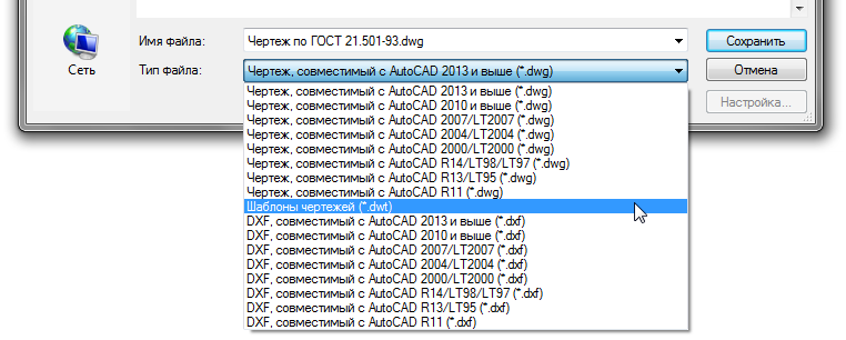
nanoCAD 5.0 DWG – R11 DOS DWG2013 Support dwg-format is our strategic advantage. And the support of a wide range of * .dwg format versions allows nanoCAD to be integrated with a huge number of third-party solutions, at least through import-export functions (for example, with Ascon solutions, Intermech, Credo, etc.). And of course, with the solutions of the company Autodesk nanoCAD can interact directly without additional conversions and re-saves, providing a unified design environment.
I also note that nanoCAD supports all the technologies associated with the * .dwg format — model list space, external links, proxy objects, creating and editing blocks, support for dynamic blocks and PDF substrates, clipboard, etc. That is why the general design principle of nanoCAD does not differ from other popular and popular CAD systems.
Command line
In nanoCAD 5.0, the command line was again improved - the command search algorithm was improved. Previously, when trying to enter characters in the command line, a window appeared with commands that began with these characters: for example, PL = PLINE. Variants of commands are now offered in which the characters entered are found not only at the beginning of the name, but also in the middle or at the end or even with a spelling error. It turned out not just a search, but an automatic correction of the entered data. No doubt comfortable ...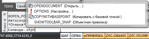
nanoCAD 5.0 – . The unique command "Paste as raster ..."
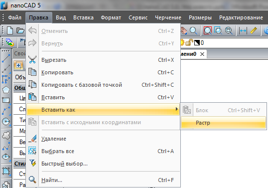
How do ordinary CAD systems work with rasters? As with the substrate. Those. the information is in the background, not editable, not used.nanoCAD takes a more intelligent approach to working with raster - this was described in a previous article . We have reinforced the new version with the unique “Paste as raster ...” function that allows you to insert a raster from the clipboard. No, it was possible to insert a raster before, but only it was inserted as an OLE object — you had to use an external editor to edit the raster, which was completely inconvenient.
Now any bitmap image that is in the clipboard comes to nanoCAD just like a raster. If a color image is copied to a buffer, a color image is inserted. If it is black and white, then a monochrome image will come to nanoCAD.
« …» nanoCAD 5.0 This functionality allows you to tightly tie nanoCAD to workflow systems, databases of regulatory documents, sources on the Internet. And along with the functions of raster editing, an interesting technology of work appears in nanoCAD: copied a sample document from the workflow system, erased the excess, finished drawing vector data over the raster (using raster binding) and that's it! With minimal effort on the basis of standard documentation, a new document has been received, tied to the current project. It is said that in some organizations up to 80% of projects are being executed exactly this way - can you imagine what speed gain they get with the new nanoCAD?
Object selection in nanoCAD 5.0
The choice of primitives - for CAD is one of the key functions. When working with saturated drawings, quickly weed out the excess - it is necessary as air. That is why we are actively working on various tools for searching, sorting, and isolating objects. And in nanoCAD 5.0 a number of new tools appeared here.Team "Quick Pick"
First, the redesigned “Quick Pick” team (QS, B-SEL). Previously, this command worked only with complex nanoCAD objects - blocks, callouts, tables, dimensions, etc. Now this function is extended to primitives - segments, arcs, circles, etc.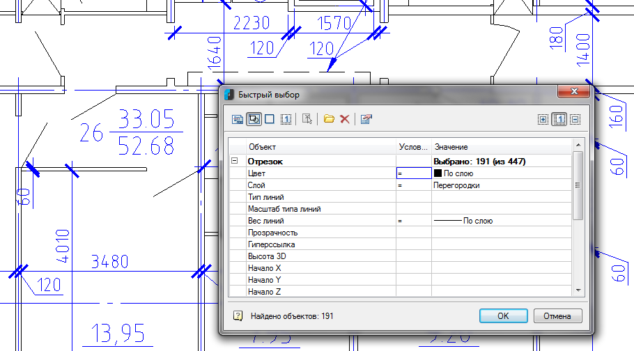
« » nanoCAD 5.0 . The dialog allows you to select, add to the selection and exclude from the selection. It can search all over the document, in the current sheet or within the specified drawing area. Search criteria can be saved and reused in subsequent work. A huge number of functions - the whole search engine.
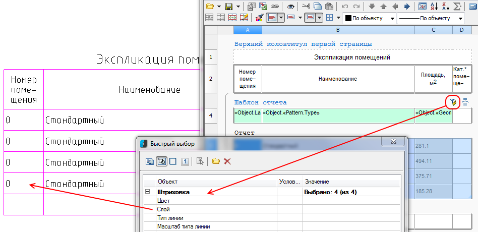
Moreover, this function is also used in tables - in any table you can add a section of the report and include automatic filling in with the properties of primitives. For example, to collect all the hatching from a certain layer and display their area in the table. And in the end to tamp the final amount of the area. The tables will be auto-updateable, fast, and auto-generated.
« » nanoCAD It would seem so much better? But there are more innovations to choose from ...
"Select Similar Objects" command (SELECTSIMILAR)
Secondly, the command “Select similar objects” (SELECTSIMILAR) has been improved - the logic of work in this team has been updated. Previously, search criteria were combined through the “logical OR” and did not allow to select objects with two or more matching criteria. Now the logic of combining the search criteria "And", a little improved dialogue - users should be satisfied: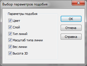
nanoCAD 5.0 « » (SELECTSIMILAR) Command to isolate objects
Thirdly, the new command to isolate objects. Of course, this is not a selection tool, but the end result of the function is similar - temporarily reducing the size of the drawing to those objects that are needed in the work. The drawing is huge, and you only work with a certain group of objects? Or vice versa - found some objects, but you do not need them temporarily in the drawing? Use the command to isolate objects - select some of the objects (even located on different layers) and leave only them. Or hide them from the drawing. Everything!
nanoCAD 5.0 And, of course, disabling this feature, you will instantly return to the original state.
New level of work efficiency with drawings
Why do you need CAD? Of course, work with documentation, drawings. In nanoCAD 5.0 we have built in a number of new convenient features for this.The order of objects
Working on a document, a pile of primitives is constantly being formed, which constantly overlap each other. In this case, you usually put the dimensions and texts on top of all the data, but the hatching should lie in the background - some kind of such stratification of the drawing into three components is formed: the text and dimensions up, the drawing data in the middle, the hatching below. In the automatic mode, it is difficult to control such a bundle, since in most cases, such a bundle is more complicated. But to implement a function that decomposes the selected primitives according to this scheme - we conceived a long time ago. And here in nanoCAD 5.0, meet a set of new functions that, in addition to the standard mechanism for managing the order, control texts, sizes and hatching.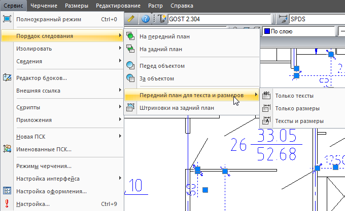
nanoCAD 5.0 , One click - and all text and dimensional objects of the drawing (or selected part of the drawing) are moved to the foreground. Another - and all the hatching "fell" on the background.
Hatching: contour search ignores design elements
Many improvements to the fifth version were suggested to us by users. Imagine a rich drawing: everything is mixed - drawing lines, callout lines, sizes, texts. If in such conditions it is necessary to specify the contour of the hatching, then each closed section of the general contour has to be clicked. “If the contour search algorithm ignored design elements, then life would be significantly simplified,” users wrote to us. “Accepted,” we replied. And in the fifth version they implemented ...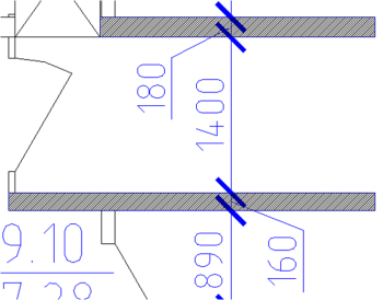
nanoCAD 5.0 In nanoCAD 5.0, the algorithm for searching the outline of hatches on saturated drawings is optimized - now it ignores design elements. One click, and the contour of the wall is shaded, despite the dimensions that cover it.
Work with tests
Any drawing contains text entries. And in texts, various special symbols are often used: designations of slopes, angles, channels, tavrs, etc. You can, of course, insert such characters by dialing special control codes like "\ u + 00B2" or "%% c". But this is not very convenient - much more conveniently, as we have done now in nanoCAD 5.0: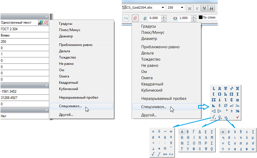
nanoCAD 5.0 And we did the following - on the MTEXT panel and in the text box of single-line text in the Properties window we added a special button with a red diameter symbol that opens a separate context menu with frequently used symbols: degree, diameter, identity, square and cubic, etc. . Plus call the Special character panel, which allows you to enter signs of slopes, I-beams, Greek letters, etc.
For texts, there are still improvements: the command "Change the text register" (TRACK, TCASE). She calls a familiar Microsoft Word dialogue and performs quite understandable actions:

nanoCAD 5.0 (TCASE) Properties Window
Another frequently used element of any CAD is the Properties window, which displays the parameters of selected objects and in some cases allows them to be edited. In nanoCAD we regularly improve this interface element.So in the fifth version we added a button in the Properties window to invoke the above commands “Quick selection” and “Select similar”. It became more convenient to display a list of user coordinate systems. For polylines, the “Closed” parameter is displayed in this window - i.e. Now you can select a polyline and close it with one click. Added at the request of users, the ability to specify the method of generating the type of lines at the vertices of the polyline: now this property can be changed for all selected polylines with two clicks in the Properties window. We learned to distinguish between AutoCAD Tables and nanoCAD Tables - respectively, now you can edit their properties separately. For external links learned how to display the path to the inserted drawing. The properties changed by the list can now be changed with the mouse wheel - often it is much faster than aiming at the elements of the list. In general, small but important changes in the Properties window are a mass!
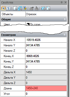
But there is a larger change that can be said about separately - it is a calculator in the Properties window. How does he work? It's very simple - select a primitive (for example, a segment), find a field with a numeric value (for example, a segment length) in the Properties window and add mathematical operations to the field value - for example, add “+240” to the length of the “1450” segment. Enter and get a new length of the segment "1690".
Other changes when working with drawings
It must be said that nanoCAD 5.0 is distinguished by a huge number of small changes, which are designed to simplify or improve the work with 2D drawings. For example, we have a more convenient setting of the scale of the on-screen display of line weights. Through the new dialog, besides the direct task, you can set the current values and units for measuring the weight of the lines, as well as quickly select the default values for the weight of the lines for each layer individually.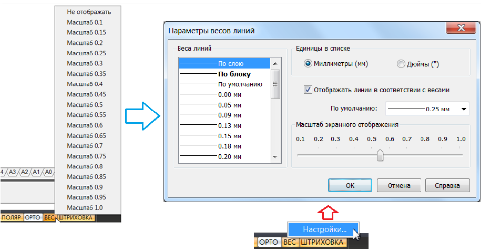
nanoCAD 5.0 Now it is possible to navigate in 3D using the “SHIFT + WHEEL-MOUSE” hotkeys — an intuitive action that is currently performed in any modern CAD system. Appeared multi-line attributes for blocks. In the External Links dialog, you can now embed (insert or embed) external links into the current drawing. Plus, the External Links dialog further notifies the user that the external link is outdated and offers to update it - very useful if your colleague is edited by your colleague on a nearby computer.
For the Copy command (COPY) a new hot key combination has been added, combined with the Move command (MOVE): now the user moves the selected object using the CTRL + D keys, and the selected copy moves with the CTRL + SHIFT + D keys object. It is logical and understandable - once done, you will not forget.
There are a lot of placers of changes - it is best to try them yourself by downloading nanoCAD 5.0 and completing a couple of drawings.
Preparation and printing of documentation
The next big part that the CAD system must flawlessly perform is the preparation and printing of documentation. And to make a convenient printing is not as easy as it may seem at first glance: to take into account various wide-format printers, not to ignore the PDF-format, to simplify work with the sheet space and viewports.Printing on non-standard formats
In previous versions of nanoCAD, we faced the fact that printing on non-standard formats (for example, Triple A1) causes difficulties for users - the algorithm for selecting such sheets was not obvious. We offered to bring these formats into the program, and they appeared in the list of formats of the Print dialog. The problem was that some wide-format printers ignored the dimensions of the sheets that the program was trying to impose on them.And in nanoCAD 5.0 we changed the logic of working with paper formats - now we accept them from the property of the printer driver. And non-standard formats that the printer can work with are automatically added to the Paper Formats section of the Settings dialog. Plus, in the Print and Sheet Settings dialogs, there is a button that also allows you to add a new non-standard format to the program without having to climb into the deep settings of the program.
Plus, we began to remember the print settings not only during the current nanoCAD session, but also between the sessions of the program.
Work with viewports
The development of printing is closely connected with the development of functionality for working with viewports. In nanoCAD 5.0, we made a more vivid toolkit for redefining the properties of layers in viewports. Pay attention to the Layers dialog - a new column has appeared in it that controls the behavior of the layer in the newly created viewports.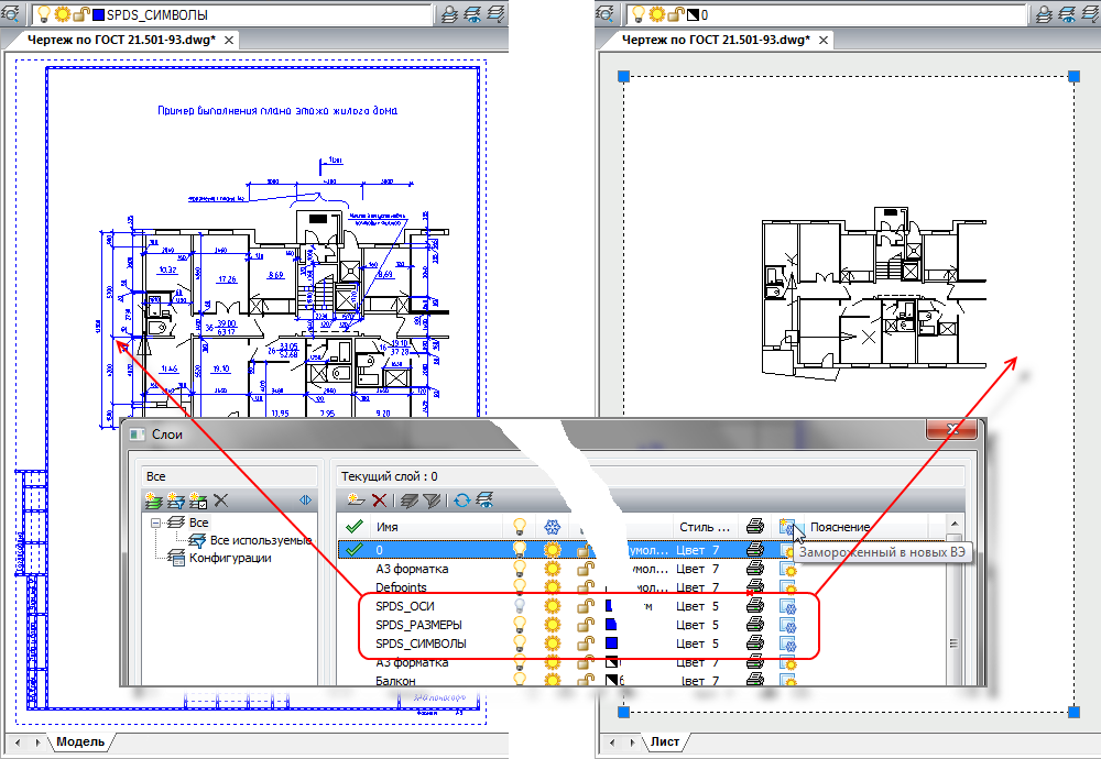
nanoCAD 5.0 , . If in this column for some layers (for example, those that begin with the characters “SPDS_”) the button is disabled, then when creating a new viewport on a sheet, these layers will be frozen by default.
It became more convenient and visual to redefine the parameters of the layers in the already created viewports. As soon as you enter the viewport editing mode on a sheet (double click inside the FE), an additional column is activated in the layer list, which controls the freezing of the layer in the current viewport. But that is not all!..
If you edit the Layers dialog while editing the viewport, then when you override the layer properties in this viewport — the frozen / thawed layer, color, line type, line weight, print style — the names of the corresponding dialog columns change, and the overridden properties are highlighted. This allows you to instantly get in fact a new drawing, obtained from the model space, but customized and drawn according to the new rules for a specific sheet!
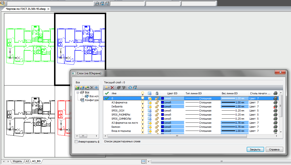
nanoCAD 5.0 This functionality simplifies the work with redefining the properties of layers in viewports so much that even an inexperienced novice can now deal with this.
Sheet Management
Perhaps, the description of the part related to the preparation and printing of documentation should be completed with the description of additional tools for managing sheets - everything has become very simple. In the previous version of nanoCAD we implemented Sheet Manager, which allowed you to move, copy, rename sheets in a separate window. Now we have duplicated these commands in the context menu of the sheet tabs:
: , , , .. Conveniently? Without a doubt…
nanoCAD as a platform - the development of the API interface
Of course, the story of the innovations nanoCAD 5.0 would be incomplete, if not to talk about the development of the API tools that help expand the functionality of the platform.Updated Developer Kit (SDK, Software Developer Kit)
The program interface (API) of nanoCAD is open to all developers. And to make it easier for you to start, the SDK includes sample projects. Quick start is so fast that it is enough to open the NCadSDK.sln solution in Visual Studio, build it, press the F5 button (by running the “Start Debugging” command) and all the examples are loaded into nanoCAD.It remains only to recall that the Developer Kit (SDK) is installed along with the program - just enable this component in the installer:
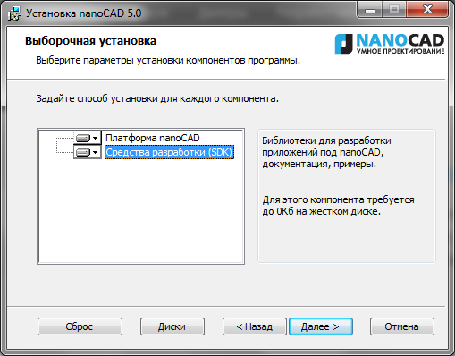
nanoCAD NanoCAD 5.0 includes the most recent changes that were discussed in the development club. The entire SDK has been tested for compatibility with new libraries for working with the DWG format (which, as we recall, have been significantly updated in connection with the implementation of the new DWG2013 format). Plus, nanoCAD 5.0 implements two highly demanded features related to application development.
Installing applications on nanoCAD
First, we implemented the ability to install applications on the nanoCAD platform. Those. You can not just develop an application, but also write an installer for the application that will find nanoCAD, add your libraries to it, and register the application in the nanoCAD environment. With all the following program launches, your application will be loaded into nanoCAD as an inseparable part.Analysis of Unrealized Functions
And secondly, nanoCAD now controls calls to third-party applications and keeps a log of those API functions that are not yet implemented in nanoCAD. What does it mean? Everything is simple ... When calling an unrealized function, nanoCAD fixes this and offers to send an informational message to the developers (ie, us). We collect such messages and analyze them, and according to the results of the analysis, we adjust the API development priorities. Thus, together we can quickly bring nanoCAD to a state that satisfies all of us.System requirements
In the end, I would like to talk a little about the nanoCAD system requirements, especially since, while developing nanoCAD, we pay a lot of attention to this. More precisely, we try to maintain an optimally reasonable balance: on one side of the scale lies the constant development of the hardware complex, which every year allows us to solve increasingly complex and complex design tasks, and the other is the fact that not all designers are able to update the computer’s hardware every year. Especially when problems to be solved do not require it. Therefore, we optimize nanoCAD for relatively weak iron and take into account modern technologies and requirements. Let's go over the components ...Hard disk space
Now the installation distribution of the nanoCAD platform takes about 120 MB.Together with .NET and Microsoft system libraries, necessary for work - no more than 340 MB. After installing nanoCAD occupies a little more than 230 MB of disk space. Agree, by modern standards - it is microscopically small. And pay attention to the closest competitors - they occupy hundreds of times more, often forcing users to download gigabytes of information from the Internet. What for? After all, even with such a small amount, nanoCAD has all the necessary functionality for the development and production of working documentation.RAM
How much memory does nanoCAD need? The answer to this question depends on which drawings you are working with. nanoCAD can be run on 512 MB - these are the minimum requirements. In this case, at least half of the RAM will be occupied by the operating system, in the other half nanoCAD will huddle along with other programs. It is unlikely that this will allow you to work comfortably, but still ... For serious work, it is recommended to use 2 GB of RAM and more.To understand how much is necessary for you to work comfortably - open your most difficult drawing (for example, in nanoCAD free) and look in the Windows Task Manager on the Processes tab. Find the process ncad.exe in the list and see how much memory it has occupied. Now, if you increase this value by one and a half to two times, you will get the amount of RAM you need on your computer.
Note that the size of the drawing on the hard disk and the size of the open drawing can vary by times - I have seen documents that, at a size of 150 MB, were “unfolded” in RAM up to 2 GB. Naturally, working with such a drawing on a computer with 1GB of RAM was difficult - Windows constantly used virtual memory on the hard disk, which on the old hardware could lead to inexplicable program crashes.
How can nanoCAD developers help in this situation? You can optimize the storage of an open drawing in RAM by placing data more compactly. And in nanoCAD 4.0-5.0, we have achieved significant success in this - in most cases, the same drawing of nanoCAD opens more compactly than its competitors. As a result, it can save on RAM and the bitness of the operating system.
Operating system and its bit
By the way, about the OS and its bit depth ... Starting with nanoCAD 5.0, the platform supports all Windows operating systems: from XP to 8. Both 32-bit and 64-bit versions. This means that nanoCAD will work with modern hardware complexes, which are most likely necessary for complex projects, and on computers that were purchased 4-5 years ago.But all the same, it is time for Windows XP and Windows Vista owners to think about updating the operating system - in the near future, Microsoft will remove these products from support and nanoCAD developers will find it harder and harder to maintain the nanoCAD performance on them every year. One or two versions of nanoCAD and, perhaps, these operating systems will be excluded from the system requirements of the platform.
And, of course, if you are now thinking about updating the computer park, then it makes sense to switch to Windows 8 with 64 bits - these computers will ensure comfortable work in the next 4-5 years.
Video card and video subsystem
Separately, I would like to talk about the video subsystem of the computer. Any graphics system (to which nanoCAD undoubtedly applies) places high demands on the video. And the richer the drawing, the more small details, texts, shading, polygons, splines and polylines, the more productive the graphics should be, the faster it should work, freeing up CPU resources. That is why we recommend not saving on video cards - professional work requires professional devices.In the case of nanoCAD, my recommendations are as follows:
- . ( ), , , . – , .
- . , .
Conclusion
Phew, it turned out to be a big article ... And despite this, I didn’t list everything that appeared new in nanoCAD - it touched only the brightest innovations of the program: the DWG format 2013, the improved command line, the raster paste command from the buffer, the introduction of external links, the insertion of special characters in multiline and single-line texts, isolation of objects, sequence for texts, sizes and hatches, calculator in the Properties window, improved navigation in three-dimensional space, improved display of hatches when panning, improved ny hatch boundary search, advanced quick selection (QSELECT), frozen layers of management in the viewports, from the shortcut menu tab sheet management, improved printing on non-standard formats, support for Windows 8.We really want to make the most convenient, most comfortable and most favorite CAD system for you! Consider also the fact that in nanoCAD 5.0 there was the most massive correction of errors and comments in the entire history of the product (more than 500). With the release of the fifth version, nanoCAD has risen not even one, but just a few steps higher on the way to the ideal goal - this can be felt independently without additional prompts after several days of work.
Find nanoCAD at www.nanocad.ru , and you can purchase the product from any CAD vendor. nanoCAD has become much closer.
Good for you projects!
Source: https://habr.com/ru/post/184918/
All Articles