Crazy DIY toy: a homemade cell phone with a built-in dosimeter. Part 1
 Hi, Habr.
By profession I am an electronics engineer, specializing in the development of devices based on microprocessors and microcontrollers, I myself am writing programs for them. Over the years, this craft has not bothered me, so even in my free time I construct all sorts of electronic crafts on the basis of controllers. It's nice to breathe a little bit of life into a small piece of iron, even if it has a reed switch at the entrance and a LED at the exit.
I was combing a turnip here the other day, on the subject of what would be useful in the household. After searching for interesting ideas on the Internet in general and on Habré in particular, it turned out that people are interested in self-made cell phones - components for similar homemade products (GSM modems, RF connectors, antennas, SIM holders) are becoming more accessible, and the topic is really interesting. For example, on Habré were published articles "Mobile phone with their own hands" ( part 1 , part 2 ) and " Designer for assembling a cell phone ."
')
Unfortunately, I already collected the self-made cellular . Of course, now a similar design would have to be done in a slightly different format - replace the AVR microcontroller with ARM, add a graphic display, instead of an antenna painted on the board, use a standard external antenna ... But this evolutionary development path is somewhat boring and it’s hardly an idea to upgrade something that has long been done and even works, evening laziness and procrastination will win. It would be much more fun if the designed shit was never done by anyone, and even better, if there were certain doubts: “Will it work?”.
Rounding out, I will only say that as a result of the search for new ideas, I decided to make a homemade cell phone with a built-in dosimeter - a thing crazy enough that it was interesting to mess with its development and practical enough so that it could be useful in the household.
In outline
An approximate specification of the phone is as follows.
Hardware stuffing:
• GSM SIM900 modem
• ARM Cortex-M3 STM32 processor
• Color display
• gamma radiation detector
• Built-in relay
• Processor ports are connected to a comb-connector, allowing you to connect additional cards
• JTAG of the processor is connected to the comb-connector, allowing you to connect a debugger and adjust the software
Software:
• Voice calls (dialing, dialing, receiving incoming)
• Quick call by pressing one key (SOS-button)
• SMS (receive, send)
• GSM and dosimeter integration (a call to a predetermined number and / or SMS generation when a radiation level exceeds a certain threshold)
• GSM and relay integration (relay call and SMS control)
• Integration of the dosimeter and the relay (switching on the relay at a certain level of radiation)
Ideology:
• “Hardware” and software (diagrams, sources, CAD files) of the dosimeter phone will be made publicly available (Open-source hardware)
Let's start the development of the device with the design of schematic fragments.
Radiation detector
 A classical radiation detector capable of detecting all types of radioactive radiation (alpha, beta and gamma) is based on a Geiger-Muller counter . In domestic dosimeters, the SBM-20 or SBM-21 counters are used, in foreign dosimeters, LND7317 is used. Geiger-Muller counters have a lot of advantages, but there are some rather disadvantages - high price and poor reachability. For example, a dosimeter based on the LND7317, even offered as part of a crowdfunding project on Kickstarter, was sold for $ 400 with the promise to sell the finished device for $ 800 (" tag, probably closer to $ 800 ").
Fortunately, there is an alternative to the Geiger-Muller counter - a PIN-diode-based semiconductor detector. Maxim even published the application note 2236, Gamma-Photon Radiation Detector, where in addition to the PIN diode, low-noise op-amps and a comparator are used. Every time a PIN diode detects a gamma quantum, a short digital pulse with a duration of several microseconds forms at the output of the circuit — the very thing to connect to the external interrupt input of the microcontroller. By accumulating statistical information about the number of detected gamma quanta for tens to hundreds of seconds, you can recalculate the obtained values (after calibration, of course) into the usual μR or mSv and show the user on the built-in display.
 I modified the original scheme somewhat:
PIN-diode replaced with BPW34S (available in Chip-Dip);
the operational amplifier was replaced with LMH6672 , and the comparator with LM311 , cheaper and more affordable (available in Promelectronics);
there are two supply voltages in the circuit, 12 and 5 V, so I added a 78L05 power supply chip, which can be bought at any radio stall; I suppose the current consumption on channel 5 V is low, so the low efficiency of the linear stabilizer has practically no effect on the total energy balance of the device. The detector circuit is here .
When using a semiconductor detector, do not forget that it "does not see" alpha and beta radiation (which, fortunately, is weakened rather quickly away from the radiation source), and in the detection of gamma radiation is inferior to a Geiger-Muller counter (as I understand process physics, high-energy gamma quanta will be detected by both types of devices, but low-energy quanta only have enough energy to energize a Geiger-Muller counter, and the detector on the PIN diode will not work; s with a question, express their opinion in the comments).
If the details specified in the diagram are not available to you, try to find analogues. The parametric search on the Kompala website often helps me in this. For example, a list of low-noise op-amps can be obtained by including the “Noise” filter in the catalog of operational amplifiers. There is a similar filtering function in the Terraelectronics catalog .
GSM modem
 Key detail of our device. Fortunately, the time has come when a full-fledged GSM / GPRS modem is really perceived as a part of the circuit - bought, sealed, working. Certain shamanism in connection with the search for bugs, features and their separation from each other, of course, is present, but in general, the threshold for entering this area is rather low.
The most popular option, in my opinion, is the GSM / GPRS modem SIM900 , the number of topics for which in the profile conference (the best source of knowledge for a novice telephone planner ), I think, confirms my point.
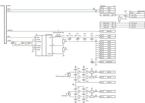
The GSM modem connection scheme is here .
Control from the central controller is implemented through UART (RXD, TXD circuits). The PWRKEY circuit is needed so that the controller can change the modem operation modes. Despite the presence of PWRKEY, it is imperative to be able to remove power from the modem by hardware (ENA circuit at pin 2 of the D1 ST1S10PHR power supply chip ). I recommend ST1S10PHR due to the combination of two pleasant features - high permissible load current (this is necessary because the GSM module according to the documentation “has the right” to consume significant current and if the power system does not provide it, the module will reboot; such current surges rarely occur, but less of them must be remembered) and low price.
Display
 Here I am still in thought.
On the one hand, there are common and proven WG12864 -type displays - monochrome, 128 x 64 pixels, data loading via a parallel interface. On the other hand, the Chinese folk industry is actively offering a colorful and cheap alternative - color TFT displays, 128 x 160 pixels, data download via SPI (greatly simplifies the routing of the printed circuit board). It is not clear whether it will be possible to buy such displays from the People's Republic of China on some more or less stable basis, or their sellers will rotate at the speed of dying flies. I ask, if someone has experience in the stable procurement of similar displays in China, unsubscribe in the comments.
So far, it seems to me the most balanced option is to design a circuit and make a printed circuit board of the phone so that both the WG12864 and some Chinese noname can be soldered onto it.
Microcontroller
In place of the controller, I see the ARM Cortex-M3 from STM.
Why ARM?
In my opinion, just recently (3-5 years ago, back), the designer of general-purpose embedded systems (not radiation, not micro-consumption) had a wide choice of controllers used. Personally, I started with PIC, then sat tight on the i8051, then I independently studied AVR and did a lot of projects already on it. However, I think now there is almost no choice. ARM does the same AVR not only in terms of price / opportunity, but also simply for the price! I do not know how this is explained by the peculiarities of production or marketing considerations, but only to me, as a developer, the transition to ARM seems inevitable and inevitable. I am pleased to hear the arguments of adherents of other architectures, but personally I have already conducted both the AVR and i8051 to a better world.
Why STM32?
I do not think that ARM controllers from STM are something fundamentally better than controllers from NXP or TI . Just when I chose which ARM to dump from the AVR, the STM32 was as good at getting as the NXP, a bit cheaper, plus the smallest STM was smaller than the smallest NXP.
From the point of view of the processor, the functionality of the dosimeter phone is fairly simple, some kind of super-performance is not needed, so the processor type STM32F101C8T6 in the TQFP-48 package is quite suitable. But bearing in mind the need to connect the keyboard (many legs), the display (also many legs) and, in particular, the external board, on which you can have all sorts of useful expandable nishtyaki, it is better to take STM32F103RBT6 in TQFP-64.
Constructive
 The design in the form of a “simple” board with details seems to me somewhat suboptimal. Of course, DIY is DIY, and the contemplation of the green PCB mask will delight the eyes of both a seasoned professional and novice amateur. Plus, as it seems to me, the self-made case , of course, performs its function (dust protection, usability etc), but somehow it kills the general aura of the device. You can use the OKW + case with a specialized membrane keyboard, which will provide excellent tactile sensations, but this will greatly increase the overall cost of the device, and the aura, again ...
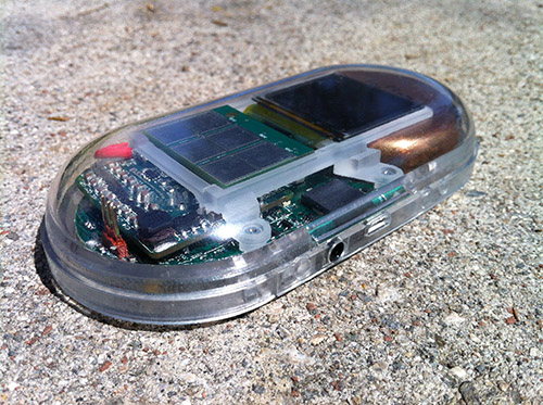
The best option seems to me to use two plates of Plexiglas - one, figured and without cutouts, closes the device from below, the other, also figured and with cutouts for buttons, display, speaker and microphone, is mounted on top. Successful examples, in my opinion - that 's it , only, perhaps, I would prefer a slightly tinted plexiglass so that the “guts” look does not interfere with the functionality.
Continue?
 As they say, "in fact, the subject." To make such a device or not? If the beginning is interested and the device with such functionality will be in demand, then the work will be continued. I will also be grateful for comments and criticism, as correcting errors at the very beginning of the project will save a lot of nerves and money later.
Source: https://habr.com/ru/post/184554/
All Articles