Creating custom primitives in CAD on the MultiCAD .NET API
One of the main disadvantages of the traditional .NET API in .dwg compatible CAD systems is the impossibility of creating custom Entities on .NET. Custom primitives are created in C ++. To use them in .NET, you need to create managed wrappers in C ++ / CLI.
The MultiCAD .NET technology allows you to create custom primitives without going beyond the scope of managed code. In addition to the lack of intermediate objects in C ++, MultiCAD .NET makes maximum use of standard .NET mechanisms, as a result, many operations familiar to CAD programmers are not needed: you do not need to manually describe serialization, you can deduce properties to the inspector without creating a COM object, etc. .
As a demonstration of MultiCAD .NET, we will look at an example of the CustomObjects application contained in the SDK package. This example creates a custom primitive, which is a rectangular frame with text inside:
')
Drawings containing our test primitive can be opened in any .dwg compatible CAD system. To change a primitive, you must load an assembly containing the primitive code, and the same assembly is loaded into all supported CAD platforms without recompilation. The technology is native to nanoCAD, the Object Enabler is required to load the module into AutoCAD. How it works see under the cut.
To create a new primitive type, you need to write a class inherited from McCustomBase - the base class for all custom primitives. In addition, for the declared class, you must use two attributes:
Now let's redefine the McCustomBase base class methods that will be used to display the geometry, insert an object into a drawing, select and transform an object.
To display an object, use the OnDraw () method. The parameter of this method is an object of the GeometryBuilder class, which, in fact, will be used to draw the user primitive.
To add a custom object to the drawing, the PlaceObject () method is used, which in our case, in addition to the actual operation of adding an object to the database, will be used to interactively enter the coordinates of the object. For interactive input in MultiCAD .NET, the InputJig class is responsible, which contains the necessary functionality:
The implementation of the
Add the ability to modify the object and edit the text string. To do this, you need to override the following methods contained in the base class McCustomBase:
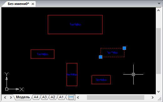
Pens are special points marked with a marker that are used to transform an object. Print the handles at the corner points of the frame, as specified by the user:
Now, after selecting an object in the drawing, pens will be displayed at the specified points:
Add the ability to move the defining corner points by dragging the handles by defining the OnMoveGripPoints () handler method:
The indexes parameter here contains the list of handle numbers, offset - the handle displacement vector.
Then we define the OnTransform () method so that when the object is transformed, new coordinates are calculated for both defining corner points:
And finally, add the ability to edit the text string inside the frame. Editing can be done by double-clicking on an object or by selecting the corresponding context menu item. When you call an editing command, a form with a text field will be called in which you can enter a new value for the line:

The MultiCAD .NET API provides the ability to add properties of a custom object to the Object Inspector, regardless of the platform where the .dwg file will be opened, be it AutoCAD or nanoCAD. This is done by adding the following attributes to the corresponding public property of the object:
Let's use this opportunity and add the Text property to the object's properties palette:
After that, the value of the text string of our object will be displayed in the object inspector:
So, we have created the first version of the primitive, which can be inserted into a drawing of the .dwg format and edited in several ways that are familiar to CAD users. But life does not stand still, and the functionality of primitives has to be increased. In one of the following articles we will look at the second version of the primitive, where we will add new fields, and tell you what features the MultiCAD.NET API provides for working with versions of primitives.
Discussion of the article is also available on our forum: forum.nanocad.ru/index.php?showtopic=6504 .
Translation of the article into English: Creating custom entities in CAD with MultiCAD .NET API .
The MultiCAD .NET technology allows you to create custom primitives without going beyond the scope of managed code. In addition to the lack of intermediate objects in C ++, MultiCAD .NET makes maximum use of standard .NET mechanisms, as a result, many operations familiar to CAD programmers are not needed: you do not need to manually describe serialization, you can deduce properties to the inspector without creating a COM object, etc. .
As a demonstration of MultiCAD .NET, we will look at an example of the CustomObjects application contained in the SDK package. This example creates a custom primitive, which is a rectangular frame with text inside:
')
Drawings containing our test primitive can be opened in any .dwg compatible CAD system. To change a primitive, you must load an assembly containing the primitive code, and the same assembly is loaded into all supported CAD platforms without recompilation. The technology is native to nanoCAD, the Object Enabler is required to load the module into AutoCAD. How it works see under the cut.
Custom primitive class
To create a new primitive type, you need to write a class inherited from McCustomBase - the base class for all custom primitives. In addition, for the declared class, you must use two attributes:
- the [CustomEntity] attribute with the class type, its GUID, the name that will be used for all such objects in the drawing database and the local name,
- attribute [Serializable], in order to use the standard serialization mechanism in the .NET Framework.
[CustomEntity(typeof(TextInBox), "1C925FA1-842B-49CD-924F-4ABF9717DB62", "TextInBox", "TextInBox Sample Entity")] [Serializable] public class TextInBox : McCustomBase { // First and second vertices of the box private Point3d _pnt1 = new Point3d(50, 50, 0); private Point3d _pnt2 = new Point3d(150, 100, 0); // Text inside the box private String _text = "Text field"; } Now let's redefine the McCustomBase base class methods that will be used to display the geometry, insert an object into a drawing, select and transform an object.
Geometry mapping
To display an object, use the OnDraw () method. The parameter of this method is an object of the GeometryBuilder class, which, in fact, will be used to draw the user primitive.
public override void OnDraw(GeometryBuilder dc) { dc.Clear(); // Set the color to ByObject value dc.Color = McDbEntity.ByObject; // Draw box with choosen coordinates dc.DrawPolyline(new Point3d[] { _pnt1, new Point3d(_pnt1.X, _pnt2.Y, 0), _pnt2, new Point3d(_pnt2.X, _pnt1.Y, 0), _pnt1}); // Set text height dc.TextHeight = 2.5 * DbEntity.Scale; // Set text color dc.Color = Color.Blue; // Draw text at the box center dc.DrawMText(new Point3d((_pnt2.X + _pnt1.X) / 2.0, (_pnt2.Y + _pnt1.Y) / 2.0, 0), Vector3d.XAxis, Text, HorizTextAlign.Center, VertTextAlign.Center); } Adding an object to the drawing, interactive input coordinates
To add a custom object to the drawing, the PlaceObject () method is used, which in our case, in addition to the actual operation of adding an object to the database, will be used to interactively enter the coordinates of the object. For interactive input in MultiCAD .NET, the InputJig class is responsible, which contains the necessary functionality:
public InputResult GetPoint(string promt)- gets a point on the drawing, selected by the user, with the ability to display prompts;public void ExcludeObject(McObjectId ObjectId)- excludes the specified object from the binding when specifying a point in the drawing. In our case, we will exclude our object from binding in order to avoid binding to itself.public EventHandler MouseMove- mouse event handler. We will use it to interactively redraw the object while moving the mouse.
The implementation of the
PlaceObject() method will look like this: public override hresult PlaceObject(PlaceFlags lInsertType) { InputJig jig = new InputJig(); // Get the first box point from the jig InputResult res = jig.GetPoint("Select first point:"); if (res.Result != InputResult.ResultCode.Normal) return hresult.e_Fail; _pnt1 = res.Point; // Add the object to the database DbEntity.AddToCurrentDocument(); // Exclude the object from snap points jig.ExcludeObject(ID); // Monitoring mouse moving and interactive entity redrawing jig.MouseMove = (s, a) => {TryModify(); _pnt2 = a.Point; DbEntity.Update(); }; // Get the second box point from the jig res = jig.GetPoint("Select second point:"); if (res.Result != InputResult.ResultCode.Normal) { DbEntity.Erase(); return hresult.e_Fail; } _pnt2 = res.Point; return hresult.s_Ok; } Editing and transformation of the object
Add the ability to modify the object and edit the text string. To do this, you need to override the following methods contained in the base class McCustomBase:
public virtual List OnGetGripPoints()- gets a list of pens for an object;public virtual void OnMoveGripPoints(List indexes, Vector3d offset, bool isStretch)- handle handling handle;public virtual void OnTransform(Matrix3d tfm)- defines how the object should be transformed;public virtual hresult OnEdit(Point3d pnt, EditFlags lInsertType)- defines the procedure for editing an object;
Pens are special points marked with a marker that are used to transform an object. Print the handles at the corner points of the frame, as specified by the user:
public override List OnGetGripPoints() { List arr = new List(); arr.Add(_pnt1); arr.Add(_pnt2); return arr; } Now, after selecting an object in the drawing, pens will be displayed at the specified points:
Add the ability to move the defining corner points by dragging the handles by defining the OnMoveGripPoints () handler method:
public override void OnMoveGripPoints(List indexes, Vector3d offset, bool isStretch) { if (!TryModify()) return; if (indexes.Count == 2) { _pnt1 += offset; _pnt2 += offset; } else if (indexes.Count == 1) { if (indexes[0] == 0) _pnt1 += offset; else _pnt2 += offset; } } The indexes parameter here contains the list of handle numbers, offset - the handle displacement vector.
Then we define the OnTransform () method so that when the object is transformed, new coordinates are calculated for both defining corner points:
public override void OnTransform(Matrix3d tfm) { //Save Undo state and set the object status to "Changed" if (!TryModify()) return; _pnt1 = _pnt1.TransformBy(tfm); _pnt2 = _pnt2.TransformBy(tfm); } And finally, add the ability to edit the text string inside the frame. Editing can be done by double-clicking on an object or by selecting the corresponding context menu item. When you call an editing command, a form with a text field will be called in which you can enter a new value for the line:
public override hresult OnEdit(Point3d pnt, EditFlags lInsertType) { TextInBox_Form frm = new TextInBox_Form(); frm.textBox1.Text = Text; frm.ShowDialog(); Text = frm.textBox1.Text; return hresult.s_Ok; } Adding object properties to the Property inspector
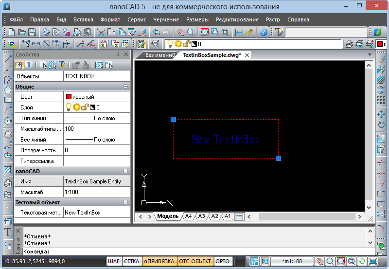
The MultiCAD .NET API provides the ability to add properties of a custom object to the Object Inspector, regardless of the platform where the .dwg file will be opened, be it AutoCAD or nanoCAD. This is done by adding the following attributes to the corresponding public property of the object:
DisplayNameAttribute- defines the name of the property that will be displayed in the inspector;DescriptionAttribute- sets the description of the property;CategoryAttribute- defines the name of the category in which this property will be displayed.
Let's use this opportunity and add the Text property to the object's properties palette:
[DisplayName(" ")] [Description(" ")] [Category(" ")] public String Text { get { return _text; } set { //Save Undo state and set the object status to "Changed" if (!TryModify()) return; // Set new text value _text = value; } } After that, the value of the text string of our object will be displayed in the object inspector:
So, we have created the first version of the primitive, which can be inserted into a drawing of the .dwg format and edited in several ways that are familiar to CAD users. But life does not stand still, and the functionality of primitives has to be increased. In one of the following articles we will look at the second version of the primitive, where we will add new fields, and tell you what features the MultiCAD.NET API provides for working with versions of primitives.
Discussion of the article is also available on our forum: forum.nanocad.ru/index.php?showtopic=6504 .
Translation of the article into English: Creating custom entities in CAD with MultiCAD .NET API .
Source: https://habr.com/ru/post/184482/
All Articles