Venus or the first 60 kpx from another planet
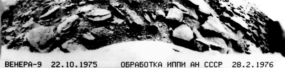
When we hear “a photograph from the surface of another planet,” then Mars comes to mind first. It is, of course, not surprising: in recent years we have been spoiled by stereoscopic HRSC images, huge resolution HiRISE panoramas, and the Curiosity rover with almost daily photo reports. And even when it comes to the background, we recall the success of the American Viking missions. But few people remember (or even know) that the first photograph in history from the surface of another planet was obtained not on Mars and not by the American apparatus, but by the Soviet station Venera-9 in 1975.
In this topic, I want to restore historical justice and talk about how Soviet engineers managed to create a device that successfully carried out a panoramic survey in extremely aggressive environments at temperatures above 470 ° C and pressures of 93 atm.
')
The history of Soviet success in learning about Venus is described quite well (yes, at least in Wikipedia ), so I will only mark the main milestones:
So, by the time the Venus-9 was launched, Soviet scientists had enough information about the conditions in which photography was to take place: first of all, these are the temperature and pressure parameters necessary for the correct calculation of engineering structures (up to Venus-4) Atmosphere was considered equal to 10 atm, which led to the destruction of this descent vehicle even before it reached the surface of the planet), as well as the illumination parameters for correct adjustment of photographic equipment (for example, due to improper exposures, photographs from Mars-2 and Mars-3 P Practical not represent scientific value).
The scientific equipment of the descent module "Venera-9" included: temperature and pressure measurement systems, a mass spectrometer for determining the chemical composition of the atmosphere, accelerometers, nephelometers (2), a photometer for studying the light mode (3 bands in the visible region + 2 IR in three solid angles), photometer for CO 2 and H 2 O absorption bands, anemometer, gamma spectrometer for determining the content of natural radioactive elements in Venusian rocks, radiation density meter to determine the density of the soil in the surface layer lanets, panoramic telephotometers (2).

To obtain an image of the surface of Venus at the landing site of the descent vehicle, the panoramic camera was installed in a sealed instrument compartment, in which normal conditions of temperature and pressure were provided for a long time. In addition, it was necessary to create an "optical window" to the surface of Venus, where the pressure could reach 100 atm and a temperature of 500 ° C, and to prevent their influence on the chamber. These circumstances required a variety of original technical and design solutions. So, two days before approaching the planet, the system was internally cooled down (down to -10 ° C). To stabilize the internal temperature regime during operation, cellular composite materials with low thermal conductivity, screen-vacuum insulation, heat accumulators from lithium nitrate trihydrate with high specific heat capacity and melting point ~ 30 ° C were used on the surface. After a 75-minute descent and hourly work on the surface of Venus, the temperature inside the descent vehicle rose from the initial -10 ° C to 60 ° C.
The set of tasks related to the provision of the required field of view of the camera and the resolution on the surface had a significant impact on the structural layout. In the NGO them. Lavochkin (the developer of the device) was considered the most expedient to position the camera in the upper zone of the instrument container. However, in view of the need to transfer both the near and far planes, the pan axis of the cameras was tilted 50 ° to the vertical axis of the landing gear. At the same time, the minimum distance from the surface to the camera was about 1 m. Thus, in the field of view of the camera, part of the device with test contrast images printed on it should have fallen. Such an arrangement of the camera made it possible to obtain an image of the surface with a low transparency of the atmosphere and to determine the photometric characteristics of the planet's surface, as well as to obtain a panorama covering a large surface area of Venus in the case of favorable weather conditions.
In the place of installation of the camera from the outside of the instrument compartment, there was a cylindrical optical porthole:
The porthole was made of thick-walled silica glass with a thickness of 10 mm with a focal length of 371 mm and a light transmission of 95%. A periscopic camera device with a scanning mirror was located inside the cylindrical window. Thus, the main heat fluxes penetrating through the window, affected only the upper part of the chamber, without reaching the electronic equipment.
To ensure a given thermal mode and eliminate the effect of high temperature on the equipment, the chamber and the porthole were fixed in the instrument compartment with the help of non-heat-conducting and heat-absorbing structural elements. The porthole was covered with powerful thermal insulation, with the exception of the viewing cut, providing the necessary field of view. The viewing cut, in turn, was closed by a thermal insulating cover, which was discharged with the help of pyro devices after landing. This ensured, firstly, the thermal regime of the chamber during the descent, and secondly, the protection of the glass of the porthole from possible smoking, precipitation and condensation on it of the gas emission products of thermal protection and any opaque precipitations from the atmosphere of Venus.
Since the Soviet engineers had a great positive experience in using optical-mechanical panoramic cameras on lunar vehicles, both fixed (Luna-E, Luna-13) and mobile (Lunokhod-1, Lunokhod-2) , and the optical and electrical characteristics of these cameras generally met the needs of the Venus mission, it was decided to use them. The only thing, in contrast to the lunar chambers that worked directly in the external environment, in this case was provided protection from particularly severe climatic influences on Venus.
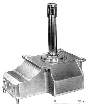
Camera assembly:

The optic-mechanical panoramic camera uses the principle of a scanning telephoto meter. The main elements of the camera and their installation on the device:

As mentioned above, the chamber was located inside a sealed and insulated housing. Surveying the surface is done through a cylindrical porthole, inside which is installed a scanning mirror and the elements of its drive. The review of the surrounding surface in the nominal angle of 40x180 ° is carried out due to two movements of the scanning mirror - rotation around the axis of panning and swing in a plane passing through this axis. To increase the reliability of image acquisition in low light conditions or very small contrasts, two sources of artificial light were installed outside, illuminating the local surface areas in two sectors of the panorama.
Camera device:
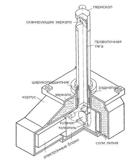
Structurally, the camera is divided into two parts: the main body and the periscope device. Periscope carried out a scanning mirror beyond the limits of heat-insulating shells and is located in the zone where the temperature could reach 475 ° . The main body with electronic units and the optical system is located in the zone where the working temperature did not exceed 40-50 ° C. The periscopic device is made in the form of a thin-walled pipe made of a material with low thermal conductivity. Swinging of the mirror from the cam and the pusher was made through a wire rod 250 mm long. The periscope tube, which rotated with a panoramic view, was mounted on ball bearings, between which a radiator was located, providing heat transfer to the housing. In the case itself, hermetic cavities were made around the perimeter, filled with lithium nitrate trihydrate, which has a high heat capacity.
Optical scheme of the camera:
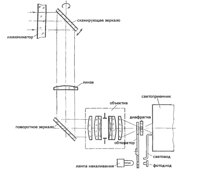
The beam of rays from the surface, passing through the window, becomes divergent in the sagittal section, as the window is a cylindrical lens (see photo above). The diverging beam falls on the scanning mirror and, being reflected from it, hits the compensating cylindrical lens, the front focus of which coincides with the rear focus of the porthole. After the lens, the beam becomes parallel again and, being reflected from a rotating mirror, passes through a lens with a focal length of 28 mm and a relative aperture of 1: 2. In the image plane there is a diaphragm, which is a sweep element forming the aperture characteristic of the camera. After the diaphragm beam enters the light receiver. At the time of horizontal flyback, the luminous flux is blocked by the shutter comb. At the same time, the photodiode is illuminated by an incandescent lamp through the hole on the obturator and generates an electrical impulse to begin reversing. During the return stroke, the instrument is calibrated. For this purpose, the light from the lamp, the brightness of which is stabilized, is fed to the light receiver by means of a light guide.
The scanning mirror oscillates (line scan), deflecting light beams at an angle of ± 20 ° with a linear angular velocity and a backward movement of 10% of the row period. At the same time, the scanning mirror rotates around the pan axis. The design of the camera made it possible to produce a full panoramic view in an angle of 360 °, however, the field of view, not covered by the elements of the apparatus itself, is approximately two times smaller, therefore the panoramic sweep is limited to an angle of 180 ± 4 °.
The optomechanical drive was a direct current motor, the rotation speed of which is stabilized using a servo system based on the frequency supplied from the onboard chronizer. The nominal angular resolution of 21 'corresponds to the clarity of 115 elements per line, which was limited not by the aperture characteristic of the cameras, but by the video signal sampling frequency (in the row direction) and the specified step of the panoramic sweep. With an angular resolution of 21 'in the near zone, surface details with dimensions of about 10 mm could be detected, and parts with dimensions several times larger should be significantly different. Camera lenses were set to hyperfocal distance, so you can get a sharp image of objects at a distance of 800 mm and further from the porthole, i.e., in all areas of the panoramic view, including the edge of the landing platform.
The main parameters of the camera:
All instruments of the landing gear, including the panoramic camera, worked in automatic mode and were controlled by a program-time device, which, after landing, gave the camera a command to turn on. After that, the camera's own automatic equipment turned on and off the illuminators in the specified viewing sectors and reversed the sweep when the camera reached the extreme positions of the panning angle. From the camera output, the video signal was fed to the encoder and then to the transmitter. Every 4 minutes, the video signal was interrupted, as telemetry information from all scientific instruments of the device came to the communication channel. And since the panoramic scan did not stop at that time, this led to the loss of 4-5 lines of the image for each measurement cycle. At the same time, the following information about the camera operation was transmitted: a change in the level of automatic sensitivity adjustment, a change in the azimuth angle, the presence of line scanning, the presence of a video signal, moments of switching on and off lights, camera temperature.
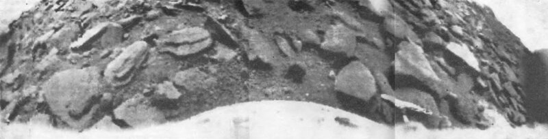
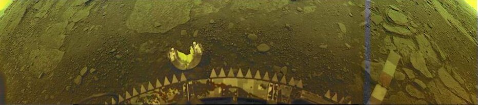
Here is the raw panorama:

After eliminating noise, this panorama began to look like this:
Some lovers found films with raw 6-bit data, on which they independently reconstructed. The most famous work of Don Mitchell :

He also carried out work on the reconstruction of images of Venus-10, Venus-13 and Venus-14.
And I would like to finish my story with an impressive color image from Venus-13. I want to sincerely believe that the breakthrough that the Soviet school has made in astronautics, despite frequent failures, will not be forgotten and the new generation of Russian scientists will make no less contribution to the cause of space exploration.
PS For all those interested, I highly recommend the site of Don Mitchell , who not only processed the original photographs of Venus, but also collected a lot of unique information about Soviet spacecraft and their scientific equipment.
In this topic, I want to restore historical justice and talk about how Soviet engineers managed to create a device that successfully carried out a panoramic survey in extremely aggressive environments at temperatures above 470 ° C and pressures of 93 atm.
')
The history of Soviet success in learning about Venus is described quite well (yes, at least in Wikipedia ), so I will only mark the main milestones:
- In 1961, the first in the history of mankind was sent the device intended for the study of other planets, "Venus-1".
- 1967 - Venus-4 became the first vehicle to penetrate the atmosphere of the planet and transfer scientific data from there.
- 1970 - the Venus-7 descent vehicle made a soft landing on the surface of Venus, information was transmitted for 53 minutes, including 20 minutes from the surface (this is the first radio communication from the surface of another planet).
- 1975 - the first black and white panoramic images from the surface of another planet ("Venus-9, 10").
- 1982 - for the first time color images of the surface were obtained and a direct analysis of the planet’s soil was carried out (“Venus-13, 14”).
So, by the time the Venus-9 was launched, Soviet scientists had enough information about the conditions in which photography was to take place: first of all, these are the temperature and pressure parameters necessary for the correct calculation of engineering structures (up to Venus-4) Atmosphere was considered equal to 10 atm, which led to the destruction of this descent vehicle even before it reached the surface of the planet), as well as the illumination parameters for correct adjustment of photographic equipment (for example, due to improper exposures, photographs from Mars-2 and Mars-3 P Practical not represent scientific value).
The scientific equipment of the descent module "Venera-9" included: temperature and pressure measurement systems, a mass spectrometer for determining the chemical composition of the atmosphere, accelerometers, nephelometers (2), a photometer for studying the light mode (3 bands in the visible region + 2 IR in three solid angles), photometer for CO 2 and H 2 O absorption bands, anemometer, gamma spectrometer for determining the content of natural radioactive elements in Venusian rocks, radiation density meter to determine the density of the soil in the surface layer lanets, panoramic telephotometers (2).
To obtain an image of the surface of Venus at the landing site of the descent vehicle, the panoramic camera was installed in a sealed instrument compartment, in which normal conditions of temperature and pressure were provided for a long time. In addition, it was necessary to create an "optical window" to the surface of Venus, where the pressure could reach 100 atm and a temperature of 500 ° C, and to prevent their influence on the chamber. These circumstances required a variety of original technical and design solutions. So, two days before approaching the planet, the system was internally cooled down (down to -10 ° C). To stabilize the internal temperature regime during operation, cellular composite materials with low thermal conductivity, screen-vacuum insulation, heat accumulators from lithium nitrate trihydrate with high specific heat capacity and melting point ~ 30 ° C were used on the surface. After a 75-minute descent and hourly work on the surface of Venus, the temperature inside the descent vehicle rose from the initial -10 ° C to 60 ° C.
The set of tasks related to the provision of the required field of view of the camera and the resolution on the surface had a significant impact on the structural layout. In the NGO them. Lavochkin (the developer of the device) was considered the most expedient to position the camera in the upper zone of the instrument container. However, in view of the need to transfer both the near and far planes, the pan axis of the cameras was tilted 50 ° to the vertical axis of the landing gear. At the same time, the minimum distance from the surface to the camera was about 1 m. Thus, in the field of view of the camera, part of the device with test contrast images printed on it should have fallen. Such an arrangement of the camera made it possible to obtain an image of the surface with a low transparency of the atmosphere and to determine the photometric characteristics of the planet's surface, as well as to obtain a panorama covering a large surface area of Venus in the case of favorable weather conditions.
In the place of installation of the camera from the outside of the instrument compartment, there was a cylindrical optical porthole:
The porthole was made of thick-walled silica glass with a thickness of 10 mm with a focal length of 371 mm and a light transmission of 95%. A periscopic camera device with a scanning mirror was located inside the cylindrical window. Thus, the main heat fluxes penetrating through the window, affected only the upper part of the chamber, without reaching the electronic equipment.
To ensure a given thermal mode and eliminate the effect of high temperature on the equipment, the chamber and the porthole were fixed in the instrument compartment with the help of non-heat-conducting and heat-absorbing structural elements. The porthole was covered with powerful thermal insulation, with the exception of the viewing cut, providing the necessary field of view. The viewing cut, in turn, was closed by a thermal insulating cover, which was discharged with the help of pyro devices after landing. This ensured, firstly, the thermal regime of the chamber during the descent, and secondly, the protection of the glass of the porthole from possible smoking, precipitation and condensation on it of the gas emission products of thermal protection and any opaque precipitations from the atmosphere of Venus.
Since the Soviet engineers had a great positive experience in using optical-mechanical panoramic cameras on lunar vehicles, both fixed (Luna-E, Luna-13) and mobile (Lunokhod-1, Lunokhod-2) , and the optical and electrical characteristics of these cameras generally met the needs of the Venus mission, it was decided to use them. The only thing, in contrast to the lunar chambers that worked directly in the external environment, in this case was provided protection from particularly severe climatic influences on Venus.
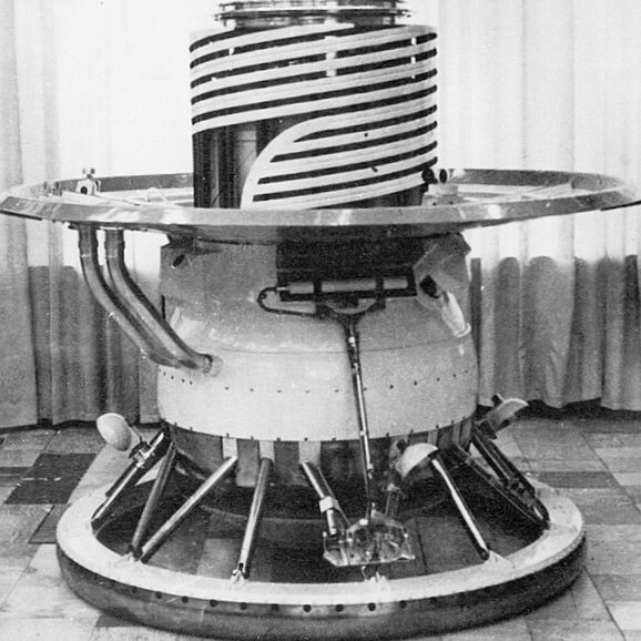
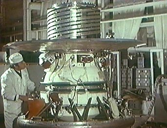
Camera assembly:
The optic-mechanical panoramic camera uses the principle of a scanning telephoto meter. The main elements of the camera and their installation on the device:
As mentioned above, the chamber was located inside a sealed and insulated housing. Surveying the surface is done through a cylindrical porthole, inside which is installed a scanning mirror and the elements of its drive. The review of the surrounding surface in the nominal angle of 40x180 ° is carried out due to two movements of the scanning mirror - rotation around the axis of panning and swing in a plane passing through this axis. To increase the reliability of image acquisition in low light conditions or very small contrasts, two sources of artificial light were installed outside, illuminating the local surface areas in two sectors of the panorama.
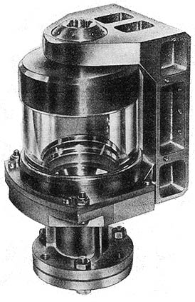
Camera device:
Structurally, the camera is divided into two parts: the main body and the periscope device. Periscope carried out a scanning mirror beyond the limits of heat-insulating shells and is located in the zone where the temperature could reach 475 ° . The main body with electronic units and the optical system is located in the zone where the working temperature did not exceed 40-50 ° C. The periscopic device is made in the form of a thin-walled pipe made of a material with low thermal conductivity. Swinging of the mirror from the cam and the pusher was made through a wire rod 250 mm long. The periscope tube, which rotated with a panoramic view, was mounted on ball bearings, between which a radiator was located, providing heat transfer to the housing. In the case itself, hermetic cavities were made around the perimeter, filled with lithium nitrate trihydrate, which has a high heat capacity.
Optical scheme of the camera:
The beam of rays from the surface, passing through the window, becomes divergent in the sagittal section, as the window is a cylindrical lens (see photo above). The diverging beam falls on the scanning mirror and, being reflected from it, hits the compensating cylindrical lens, the front focus of which coincides with the rear focus of the porthole. After the lens, the beam becomes parallel again and, being reflected from a rotating mirror, passes through a lens with a focal length of 28 mm and a relative aperture of 1: 2. In the image plane there is a diaphragm, which is a sweep element forming the aperture characteristic of the camera. After the diaphragm beam enters the light receiver. At the time of horizontal flyback, the luminous flux is blocked by the shutter comb. At the same time, the photodiode is illuminated by an incandescent lamp through the hole on the obturator and generates an electrical impulse to begin reversing. During the return stroke, the instrument is calibrated. For this purpose, the light from the lamp, the brightness of which is stabilized, is fed to the light receiver by means of a light guide.
The scanning mirror oscillates (line scan), deflecting light beams at an angle of ± 20 ° with a linear angular velocity and a backward movement of 10% of the row period. At the same time, the scanning mirror rotates around the pan axis. The design of the camera made it possible to produce a full panoramic view in an angle of 360 °, however, the field of view, not covered by the elements of the apparatus itself, is approximately two times smaller, therefore the panoramic sweep is limited to an angle of 180 ± 4 °.
The optomechanical drive was a direct current motor, the rotation speed of which is stabilized using a servo system based on the frequency supplied from the onboard chronizer. The nominal angular resolution of 21 'corresponds to the clarity of 115 elements per line, which was limited not by the aperture characteristic of the cameras, but by the video signal sampling frequency (in the row direction) and the specified step of the panoramic sweep. With an angular resolution of 21 'in the near zone, surface details with dimensions of about 10 mm could be detected, and parts with dimensions several times larger should be significantly different. Camera lenses were set to hyperfocal distance, so you can get a sharp image of objects at a distance of 800 mm and further from the porthole, i.e., in all areas of the panoramic view, including the edge of the landing platform.
The main parameters of the camera:
| Number of elements in a row (without backtracking) | 115 |
| The number of rows in the panorama | 517 ± 13 |
| The number of elements in the reverse course | 13 |
| Time line | 3.5 |
| Panorama transfer time, min | 30 ± 0.9 |
| Transmission density range | 0-1,2 (1, 5) |
| Number of video quantization levels | 64 (6 bits) |
| Camera weight, kg | 5.8 (including lithium salts - 2.1 kg) |
| Power consumption, W | five |
Here is the raw panorama:
After eliminating noise, this panorama began to look like this:
Some lovers found films with raw 6-bit data, on which they independently reconstructed. The most famous work of Don Mitchell :
He also carried out work on the reconstruction of images of Venus-10, Venus-13 and Venus-14.
And I would like to finish my story with an impressive color image from Venus-13. I want to sincerely believe that the breakthrough that the Soviet school has made in astronautics, despite frequent failures, will not be forgotten and the new generation of Russian scientists will make no less contribution to the cause of space exploration.
PS For all those interested, I highly recommend the site of Don Mitchell , who not only processed the original photographs of Venus, but also collected a lot of unique information about Soviet spacecraft and their scientific equipment.
Source: https://habr.com/ru/post/184444/
All Articles