Networks for the smallest. Part Eight BGP and IP SLA
All issues
8. Networks for the smallest. Part Eight BGP and IP SLA
7. Networks for the smallest. Part Seven. VPN
6. Networks for the smallest. Part six. Dynamic routing
5. Networks for the smallest: Part Five. NAT and ACL
4. Networks for the smallest: Part Four. STP
3. Networks for the smallest: Part Three. Static routing
2. Networks for the smallest. Part two. Switching
1. Networks for the smallest. Part one. Connection to the equipment cisco
0. Networks for the smallest. Part zero. Planning
Until now, we have been cooking in our own juice - VLANs, static routes, OSPF. They grew smoothly above themselves from green students into strong engineers.
Now we set aside these toys, it's BGP time.
Today we
- We deal with the BGP protocol: types, attributes, principles of operation, configuration
- Connecting to BGP provider
- We organize the reservation and load distribution between several links.
- Consider a backup option without using BGP - IP SLA
First, let's refresh the basics of dynamic routing protocols.
There are two types of protocols: IGP (internal to your autonomous system) and EGP (external).
Both those and others rely on one of two algorithms: DV (Distance Vector) and LS (Link State).
Internal we have already considered . These include ISIS / OSPF / RIP / EIGRP. They are needed in order to ensure the distribution of routing information within your network.
')
EGP represents only one protocol - BGP - Border Gateway Protocol. It is designed to ensure the transfer of routes between different networks (autonomous systems).
Roughly speaking, the joint between Balagan Telecom and its uplink provider will be precisely organized through BGP.
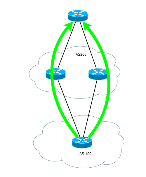
That is, the application scheme is approximately as follows:

Autonomous systems - AS
BGP is inextricably linked with the concept of the Autonomous System (AS - Autonomous System), which has repeatedly met in our cycle.
According to the definition of a wiki, an AS is a system of IP networks and routers managed by one or several operators with a single routing policy with the Internet.
To make it a little clearer, you can, for example, imagine that a city is an autonomous system. And as the two cities are interconnected by highways, so the two AUs communicate with each other BGP. In addition, within each city has its own road system - IGP.
Here is how it looks from a short distance:

In BGP AS, this is not just some abstract thing for convenience. This thing is very formalized, there are special windows in the network where you can get an autonomous system number on weekdays from 9 to 6. The issue of these numbers are engaged in RIR (Regional Internet Reistry) or LIR (Local Internet Registry).
In general, IANA is doing this globally. But in order not to burst, it delegates its tasks to the RIR - these are regional organizations, each of which is responsible for a certain part of the planet (For Europe and Russia, this is the RIPE NCC)

LIR can be almost any organization with the necessary documents. They are needed so that the RIR does not have to strain with requests from such small offices as LinkMiAp.
Well, for example, Balagan Telecom could be LIR. And we took ASN (AC number) from him - 64500, for example. And he himself has AS 64501.
Until 2007, only 16-bit AS numbers were possible, that is, a total of 65536 numbers were available. 0 and 65535 are reserved.
Numbers 64512 to 65534 are for private ASs that are not routed globally — something like private IP addresses.
Numbers 64496-64511 - for use in examples and documentation, which we will use.
Now it is possible to use 32bit AS numbers. This transition is much easier than IPv4-> IPv6.
Again, you can not talk about autonomous systems without reference to blocks of IP-addresses. In practice, each AS should be associated with a block of addresses.
PI and PA addresses
At the time of my professional youth, while reading the contract with our LIR, I laughed at the managers who could not write the IP-address correctly: the word “PI-address” was encountered in the text.
Thank God it was enough then mind google this question
In fact, PI is a Provider Independent.
In a normal situation, when you connect to the provider, it gives you a range of public addresses - the so-called PA addresses (Provider Aggregatable).
To get them is to spit once, but if you are not an LIR, then when changing providers, you will have to return PA addresses. Moreover, it is actually allowed to connect to only one provider.
And if you decide to change the provider, the old addresses will go along with it, and the new provider will issue new ones. So where is the flexibility?
From LIR, you can purchase a custom-independent address block (PI) and necessarily an ASN. In our case, let it be a block 100.0.0.0/23, which we will announce on BGP to our neighbors. And these addresses are purely ours and we are not afraid of any providers: we didn’t like one — went to another with the preservation of our addresses.
Getting PI addresses was never easy. You need to prepare a lot of documents, justify the need for such a unit, and so on .
Now with the exhaustion of IPv4, getting big blocks is getting harder. The RIR no longer issues them, and the LIR distributes the latter.
Thus, both AS numbers and PI addresses can be obtained in the same offices.
After receiving all this farming, you will need to make more changes to the RIPE database. The case is troublesome, difficult and have a long time to understand.
Here is a brief tutorial on RIPE database objects.
Suppose that in our case LinkMiAp received a block of addresses 100.0.0.0/23 and AS 64500. Returning to our analogy, we gave the city a name and supplied it with a range of indices.
Another article on this topic .
Short FAQ
Bgp
So, in order for us from our AS to transfer information about these public addresses to another AS (read on the Internet), BGP is used. And if you think that Yandex or Microsoft is using some kind of heavenly technology to connect their data centers to the Internet, then you are mistaken - all the same BGP.
Now the main question that is always interested in newbies: why BGP, why not take the notorious OSPF or even static?
Perhaps the great uncles can explain this in great detail and thoroughly, but we will try to give a superficial understanding.
- If we talk about OSPF / IS-IS, then these are Link-State algorithms, which imply (attention!) That every router knows the topology of the entire network. We imagine millions of routers on the Internet and discard the idea of using Link State for this purpose in general.
In general, OSPF for routing between areas is actually a distance vector protocol. Hypothetically, it would be possible to replace “AS” with “Area” in terms of global routing, but OSPF is simply not designed to digest such volumes of routing information, and it is impossible to select Area 0 on the Internet.
RIP, EIGRP ... Khe-khe. Well, everything is clear.
- IGP is something intimate and it’s not worth showing it to every oncoming ISP. Even without AS, the situation when a client picks up an IGP with a provider is extremely rare (with the exception of L3VPN). The fact is that IGPs do not have a sufficiently flexible route management system - for LS protocols, it is generally known to know all or nothing (again, you can filter on the border of the zone, but there is no flexibility).
As a result, it turns out that you have to open to someone else's hidden parts of your private network or set up tricky import policies between different IGP processes.
“There are currently over 450,000 routes on the Internet. If even OSPF / ISIS could store the entire topology of the Internet, imagine how long the SPF algorithm would take.
Here is a good example of how dangerous it is to use IGP where something global is being suggested.
Therefore, we need our own special protocol for communication between ASs.
Firstly, it must be vector-distant - this is unambiguous. The router should not calculate the route to each network on the Internet, it only has to choose one of several proposed ones.
Secondly, it must have a very flexible route filtering system . We must easily determine what to shine neighbors, and what should not be taken out of the hut.
Thirdly, it should be easily scalable , have loops protection and a route priority management system .
Fourth, it must be highly stable . Since route data will be transmitted through an environment that may not always have guaranteed quality (at least two organizations are responsible for the junction), it is necessary to exclude possible losses of route information.
Well and logical, fifthly, he should understand what an AS is, distinguish one's AS from others.
Meet the: BGP .
In general, the description of the work of this truly ambitious protocol will be divided into two parts. And today we consider the fundamental points.
BGP is divided into IBGP and EBGP.
IBGP is required to transfer BGP routes within a single autonomous system. Yes, BGP is often launched inside the AS, but we'll talk about it another time.
EBGP is a common BGP between autonomous systems. On it and stop.
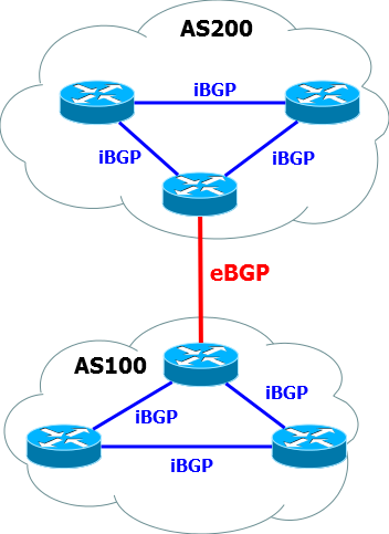
Establishing a BGP session and route exchange procedure
Let's take a typical situation when we have a connection to the provider gateway organized directly.
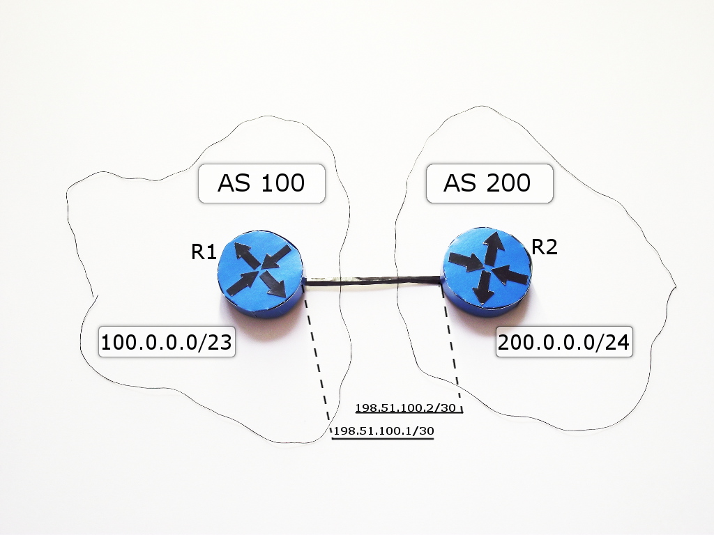
The devices between which a BGP session is established are called BGP peers or BGP neighbors.
BGP does not automatically detect neighbors — each neighbor is configured manually.
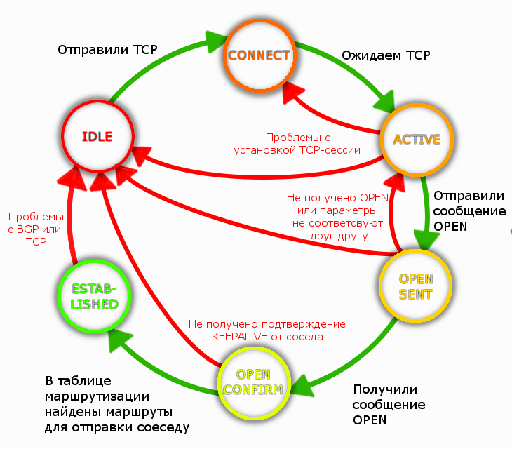
The process of establishing neighborhood relations is as follows:
I) The initial state of the BGP neighborhood is IDLE . Nothing happens.

BGP is at IDLE if there is no route to the BGP neighbor.
Ii) To ensure reliability, BGP uses TCP.
This means that theoretically BGP peers can be connected not directly, but, for example, like this .
But in the case of connecting to the provider, as a rule, a direct connection is taken, so there is always a route to the neighbor, as connected directly.
The BGP router (also called BGP speakers / speaker or BGP speakers) listens and sends packets to the 179th TCP port.
When listening, this is a CONNECT state. In this state, BGP is very short.
When sent and waiting for a response from a neighbor - this is the ACTIVE state.

R1 sends TCP SYN to neighbor port 179, initiating a TCP session.
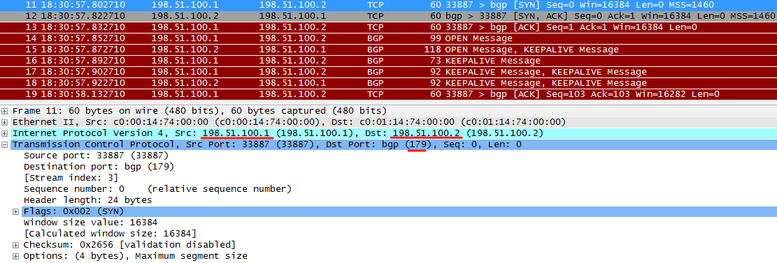
R2 returns TCP ACK, they say, everything is received, I agree with your TCP SYN.

R1 also reports that it received a SYN from R2.
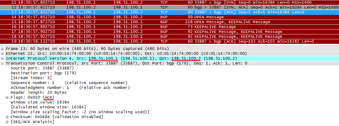
After this, the TCP session is established.
In the ACTIVE state, the BGP may hang if
- no IP connectivity with R2
- BGP not running on R2
- port 179 closed ACL
Here is an example of a failed TCP session establishment. BGP will be able to ACTIVE, sometimes switching to IDLE and back again.
TCP SYN sent from R1 to R2.
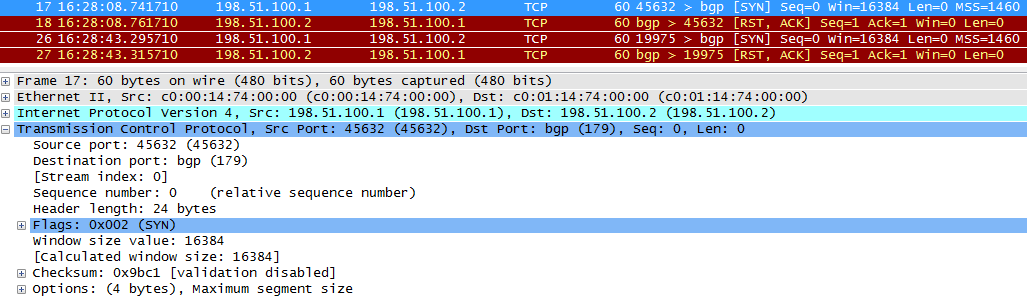
BGP is not running on R2, and R2 returns an ACK that a SYN is received from R1 and RST, meaning that you need to reset the connection.

Periodically, R1 will try to set up a TCP session again.
When I was a green boy, I, for the first time setting up BGP peering with a provider, spent half a day searching for a problem. I really didn’t know how to configure BGP and was looking for a configuration error, I thought that there were some subtleties for my situation, I already started reading about the community. But at last a bright thought came to mind - check the ACL at the entrance to the network. Yes, TCP requests from the provider fell into deny and the session was not established.
Be careful. Ordinary practice for the provider to hang on all of its external interfaces, sticking into the "world" ACL.
III) After a TCP session is established, BGP speakers begin exchanging OPEN messages.
OPEN is the first type of BGP message. They are sent only at the very beginning of the BGP session to agree on the parameters.
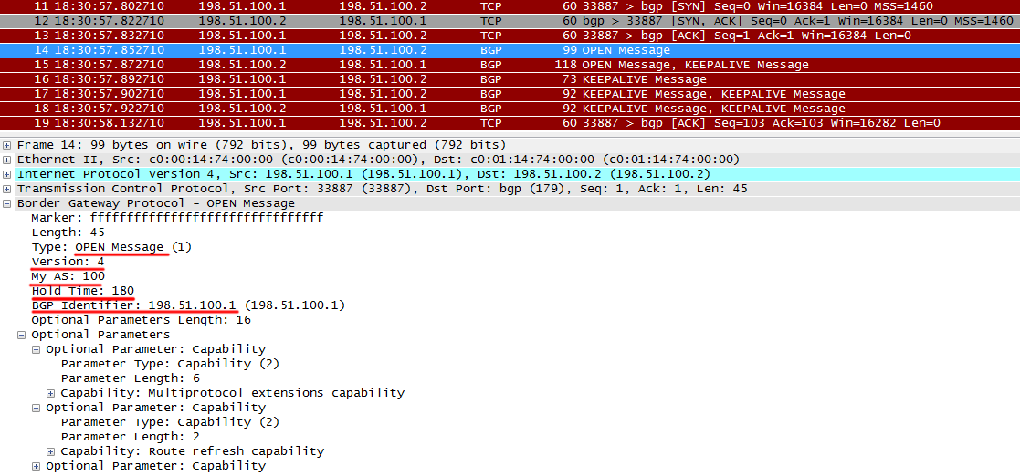
It transmits the protocol version, AS number, Hold Timer and Router ID. For a BGP session to rise, the following conditions must be met:
- Protocol versions must be the same. It is unlikely that it will be different
- AS numbers in the OPEN message must match the settings on the remote side
- Router ID must be different
Also below you can see if the router supports additional protocol features.
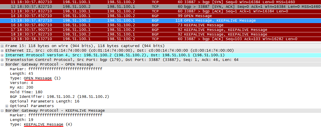
After receiving OPEN from R1, R2 sends its OPEN, as well as KEEPALIVE, indicating that OPEN is received from R1 - this is a signal for R1 to move to the next state - Established.
Here are examples of inconsistency parameters:
a) incorrect AS (AS 300 is configured with AS 300, whereas, as with R1, it is considered that this neighbor is in AS 200):
R2 sends normal OPEN
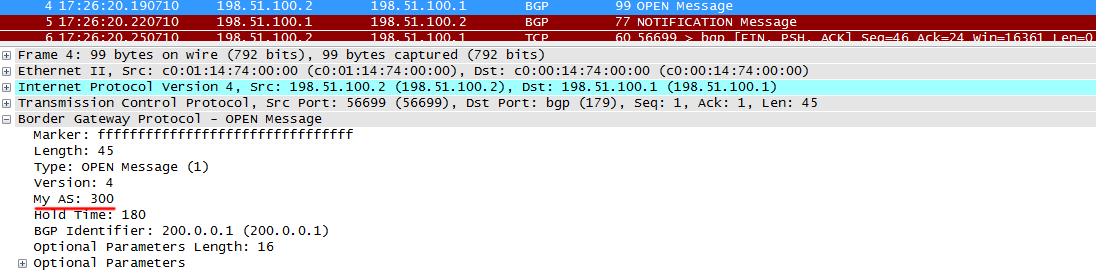
R1 notices that the AS in the message does not match the configured one, and resets the session by sending a NOTIFICATION message . They are sent in case of any problems in order to break the session.
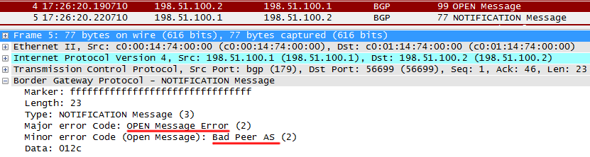
In this case, the following messages appear in the R1 console:

 b) the same Router ID
R2 sends to OPEN Router ID, which is the same as R1 ID:
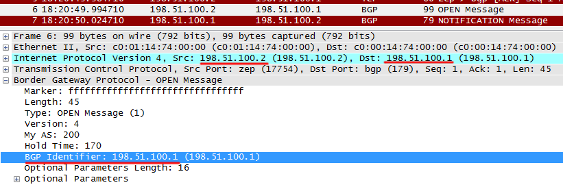
R1 returns NOTIFICATION supposedly swollen ?!

In this case, the console will have the following message plan:


After such errors, BGP goes to IDLE first, and then to ACTIVE, trying to re-establish a TCP session and then exchange OPEN messages again, what if something has changed?
When an Open message is sent, this is the OPEN SENT state.
When it is received - this is OPEN CONFIRM .
If Hold Timer is different, then the smallest will be selected. Since the Keepalive Timer is not transmitted in the OPEN message, it will be automatically calculated (Hold Timer / 3). That is keepalive may vary on neighbors
Here's an example: on R2, the timers are configured like this: Keepalive 30, Hold 170.
R2 sends these parameters in an OPEN message. R1 gets it and compares: the resulting value is 170, its 180. Choose the smaller one - 170 and calculate the Keepalive timer:
This means that R2 will keep its keepalives every 30 seconds, and R1 - 56. But the main thing is that they have the same Hold Timer, and none of them will terminate the session ahead of time.


It is almost impossible to see the status of OPENSENT or OPENCONFIRM - BGP does not linger on them.
Iv) After all these steps, they become stable in ESTABLISHED .
This means that the correct version of BGP is running and all settings are consistent.
For each neighbor, you can watch Uptime - how long is it in the ESTABLISHED state.
 V) In the first moments after setting up a BGP session in the BGP table, only information about local routes.
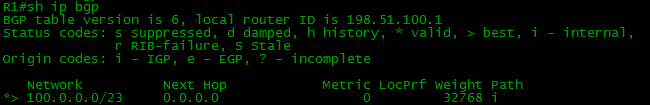
You can proceed to the exchange of route information.
UPDATE messages are used for this.
Each UPDATE message can carry information about one new route or about deleting a group of old ones. And at the same time.

Let us examine them in more detail.
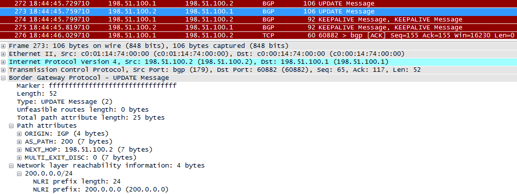
R1 sends routing information to R2.
The first plus sign in the UPDATE message is the path attributes. We will look at them in detail later, but you should already understand two of them. AS_PATH means that the route came from AS with the number 100.
NEXT_HOP - which is logical, information for R2, what to specify as a gateway for this route. Theoretically, this may not necessarily be the address R1.
The ORIGIN attribute reports the origin of the route:
- IGP - manually set with the network command or received via BGP !!!!!!!!!!!!!!!!
- EGP - this code you will never meet, means that the route is derived from the obsolete protocol, which was called “EGP”, and was completely replaced by BGP
- Incomplete - most often means that the route is obtained through redistribution
The second plus sign is the route information itself - NLRI - Network Layer Reachability Information. Actually, our network 100.0.0.0/23 is here indicated.
Well, UPDATE from R2 to R1.
The following KEEPALIVIE is a kind of confirmation that the information has been received.
Network information now appears in the BGP table:

And in the routing table:

UPDATE is transmitted for every change in the network for as long as the BGP session lasts. Note that there are no synchronization of the routing tables, in contrast to any OSPF. That would be technically stupid - a complete table of BGP routes weighs several tens of megabytes on each neighbor.
VI) Now that everything is fine, each BGP router will regularly send KEEPALIVE messages . As in any other protocol, this means: "I am still alive." This happens when the keepalive timer expires - the default is 60 seconds.
If the BGP session is established normally, but then it breaks and it repeats with a certain periodicity - a sure sign that keepalive does not pass. Most likely, the cycle period is 3 minutes (the default HOLD timer). Look for the problem on L2. For example, it may be poor communication quality, overload on the interface or CRC errors.
Another type of BGP message - ROUTE REFRESH - allows you to request from your neighbors all routes again without restarting the BGP process.
Read more about all types of BGP messages.
The full FSM ( state machine ) for BGP looks like this:
 Found in the network a detailed description of each step.
Backfill question: Suppose that the Uptime BGP session is 24 hours. What messages are guaranteed not passed between neighbors last 12 hours?
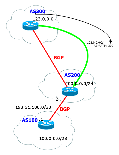
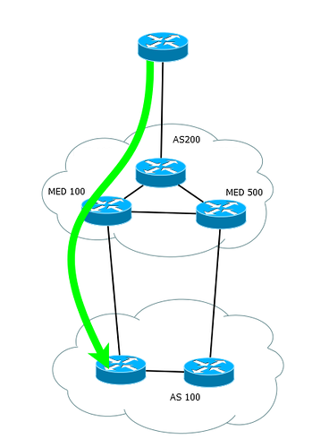
Now let's expand our horizons to this network:
Pictures without subnets

And let's see what the BGP route table on R1 is:

As you can see, the route is not only NextHop or just a list of devices to the desired subnet. This is an AS list. Otherwise, it is called AS-Path.
That is, to get into the network 123.0.0.0/24 we have to send the packet out, overcome AS 200 and AS 300.
AS-path is formed as follows:
a) while the route is walking inside the AS, the list is empty. All routers understand that the received route is from the same AS.
b) As soon as the router announces a route to its external neighbor, it adds its AS number to the AS-path list.
c) inside the neighboring AS, the list does not change and contains only the number of the original AS
d) when the route is transferred further from the neighbor AS to the top of the list, the current AS number is added.
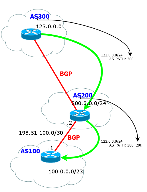
And so on. When a route is transmitted to an external neighbor, the AS number is always added to the top of the AS-path list. That is actually a stack.
The AS-path is needed not just for the R1 router to know the path to the destination network - after all, essentially Next Hop is enough - each router still takes a decision based on the routing table. In fact, there are two more important goals:
1) Prevent routing loops. There should be no duplicate numbers in AS-Path
In fact, the ASN can be repeated in the AS-Path in two cases.
a) When you use AS-Path Prepend, which is described below.
b) When you want to connect two pieces of one AS that do not have a direct connection with each other.
2) Choosing the best route. The shorter the AS-Path, the more preferable the route, but more on that later.
BGP setup and practice
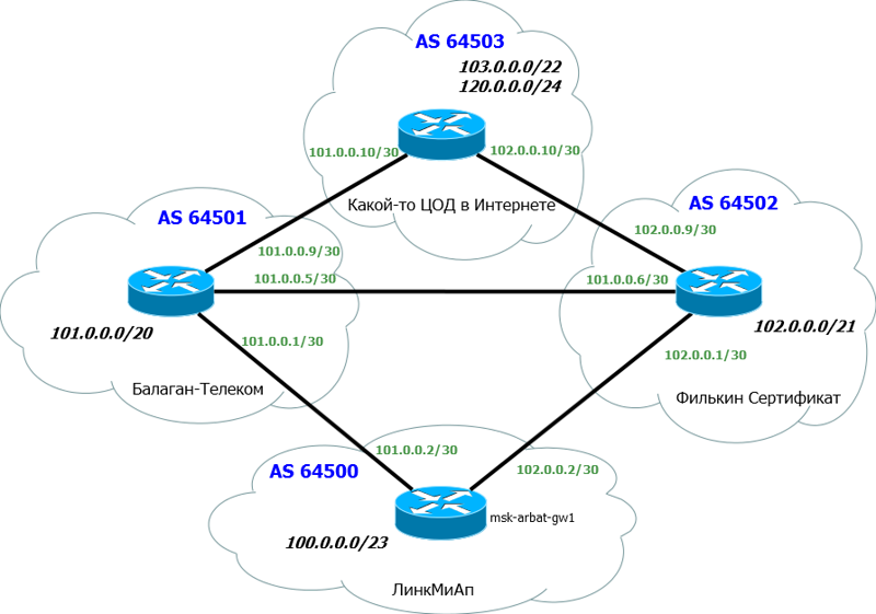
In this issue, we mix theory with practice, because it will be the easiest to understand. Actually now we turn to our network LinkMiAp.
As usual, cut off all unnecessary and add the necessary:

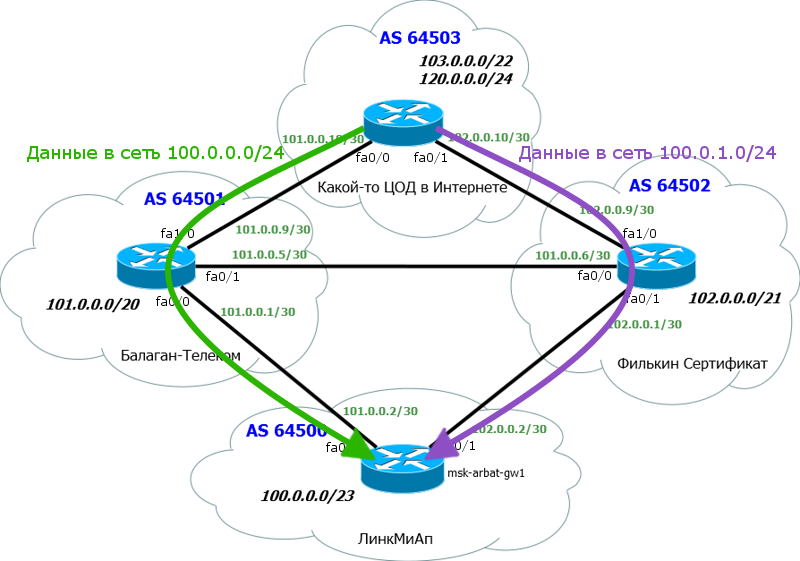
Below is our main msk-arbat-gw1 router. To simplify the settings and understanding, we will abandon all the old settings and free interfaces.
Above are two of our old providers - Balagan Telecom and Filkin Certificate.
Of course, each provider has its own AS. We have added another dead-end AS - before it and we will check, let it be, for example, a data center on the Internet.
For simplicity, we assume that each AS is represented by only one router, no ACLs, no intermediate devices.
We are raising a BGP session with both providers.
The following information is important to us:
1) Our AS number and block of IP addresses. We have already received them: AS64500 and block: 100.0.0.0/23.
2) AS “Balagan Telecom” number and link subnet with it. AS64501 and link network: 101.0.0.0/30.
3) AS "Filkin Certificate" and link subnet with it. AS64502 and link network: 102.0.0.0/30.
When connecting via BGP, the public addresses with a subnet mask / 30 are usually used as link addresses, and the superior provider issues them to us.
This is done for the simple reason that your traffic everywhere goes to public addresses and in the middle of the trace does not appear every 10.H.H.H. Not that this is something forbidden, but usually still adhere to this rule.
Let's start with the banal.
Interface configuration:
msk-arbat-gw1 R1(config)#int fa0/0 R1(config-if)#ip address 101.0.0.2 255.255.255.252 R1(config-if)#no shutdown R1(config)#int fa0/1 R1(config-if)#ip address 102.0.0.2 255.255.255.252 R1(config-if)#no shutdown 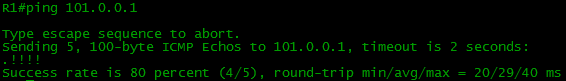
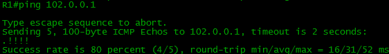
Now let's assign some address to the Loopback interface, then check the connectivity:
R1(config)#int loopback 0 R1(config-if)#ip address 100.0.0.1 255.255.255.255 BGP turn. Here we will focus on each line.
R1(config)#router bgp 64500 First we start the BGP process and specify the AS number. That is the number that issued the LIR. This is not OSPF for you - liberties are not allowed.
Now raise the peering.
R1(config-router)#neighbor 101.0.0.1 remote-as 64501 With the neighbor command, we specify with whom to establish the session. The router will send TCP-SYN first, and then OPEN to the address 101.0.0.1. We must also indicate the number of the remote Autonomous System - 64501.
The configuration on the reverse side is symmetrical:
R2(config)#router bgp 64501 R2(config-router)#neighbor 101.0.0.2 remote-as 64500 Already on one message
*Mar 1 00:11:12.203: %BGP-5-ADJCHANGE: neighbor 101.0.0.2 Up it can be judged that the BGP has risen, but let's check its condition:
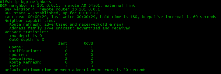
Here they ran through all the states and now their status is Established.
Our router received and sent one OPEN one at a time and during this time managed to send and receive 2 KEEPALIVE.
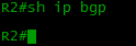
With the command sh ip bgp you can see which networks are known to BGP:
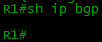
Is empty. It is necessary to indicate that we have this grid here 100.0.0.0/23 and transfer it to providers?
There are three options for this:
- define network with network command
- import from another source (direct, static, IGP)
- create an aggregated route using the aggregate-address command
Looking ahead, we note that the network has a higher priority, and with the import you need to be careful not to grab the surplus.
R1(config)#router bgp 64500 R1(config-router)#network 100.0.0.0 mask 255.255.254.0 See if our network appeared in the table:
Strange, but no, nothing appeared. On R2 too.
But the point here is that the exact network has to be in the network that you registered with the network command, otherwise it will not be added to the BGP table - this is a mandatory condition. Of course, there is no such route. Where did he come from:
Since we really have nowhere to register such a route - except for one Loopback interface, nowhere is this network anywhere, we can do the following:
R1(config)#ip route 100.0.0.0 255.255.254.0 Null 0 This route indicates that all packets in this subnet will be dropped. But do not worry, normal work will not be disrupted. If you have more accurate routes (with a mask greater than / 23, for example, / 24, / 30, / 32), then they will be preferable according to the Longest Prefix Match rule.
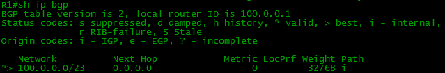
And now in the BGP table there is our local route:
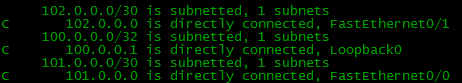
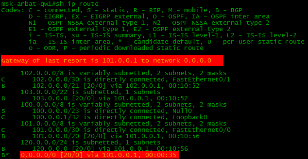
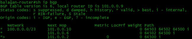
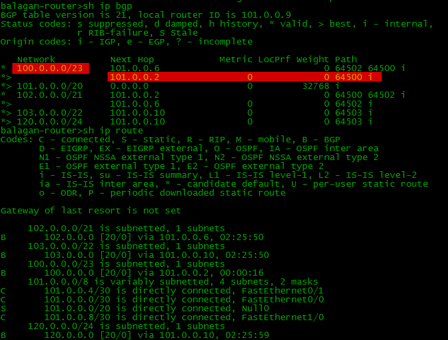
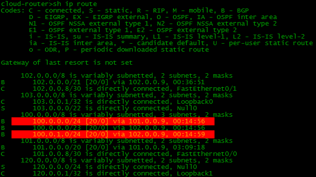
If you configure BGP and the necessary routes on all devices of our scheme, then the BGP and routing tables on our border (border - router on the edge of the network) will look like this:


Note that there are 2 routes to some networks in the BGP table, and only one in the routing table. The router selects the best of all and only transfers it to the routing table. We will talk about this later .
This is a necessary minimum, after which there will already be a little happiness.
=====================
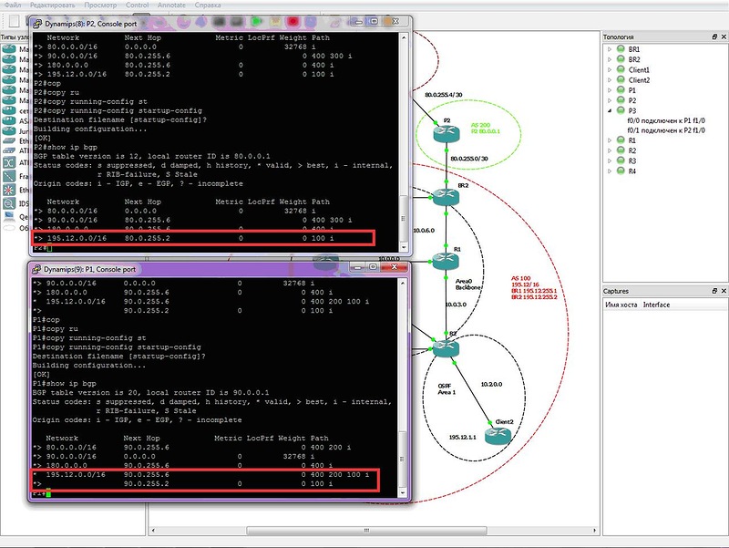
 Problem number 1
Scheme:

Condition:
Router settings are irrelevant. No route filters are configured. Why on one of the neighbors there is no alternative route to the network 195.12.0.0/16 through AS400?
Details of the task on the site
=====================
Full View and Default Route
Speaking of BGP and connecting to providers, one can not touch on this topic. When LinkMiAp, having already AS and PI-addresses, will make a joint with Balagan Telecom, one of the first questions from them will be: “Full view or Default?”. The main thing is not to get confused and not to blink nonsense.
What you have seen so far is the so-called Full View - the router studies absolutely all the routes of the Internet, even if in our case it’s five or six pieces. In reality, there are now more than 400,000 of them. Accordingly, you will receive 400k routes from one provider, the same from the second. Sometimes there is a third backup - plus another 400k. Total more than a million.
Well, not to buy now a little underinterpreting a tsiska of the senior series just for this?
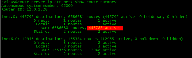 * output of the routing table from one of the public servers (accessible via telnet route-server.ip.att.net)
In fact, not everyone who has AS, needs Full View. Usually for such companies as ours, it is quite enough for Default Route, by names it’s quite clear how they differ. In the latter case, there is only one default route from each provider, instead of hundreds of thousands of specific ones (although, in general, it may be together).
Let me give a small argument for both.
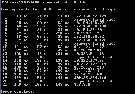
- Full View . You have a complete knowledge of the structure of the Internet. To any Internet address, you can view the path from yourself:
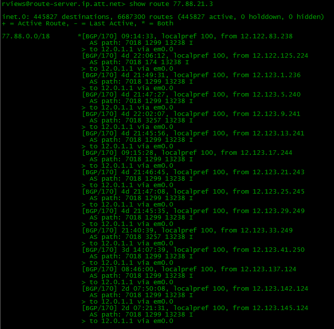
You know what AS leads to it. Through the RIPE website you can see which providers provide transit. You follow all the changes. If suddenly someone drops something through the first link (not even from you or the provider, but somewhere else, further on), BGP will track this and rebuild its routing table to transfer data through the second provider.
At the same time, you can manage routes very flexibly, interfering with the standard procedure for choosing the best path.
For example, you will start all traffic on Yandex through Balagan Telecom, and on Google through Filkin Certificate. This is called load distribution .
This is achieved by configuring, for example, route priorities for certain prefixes.
Full View is required if your speaker system is transit, that is, you are going to connect other clients to yourself via BGP.
You have to pay for all these advantages with performance: high utilization of RAM and a very long study of routing information after establishing a BGP session. For example, after a link with a higher provider is jerked, a full recovery may take several minutes. - Default route
Well, first of all, this, of course, greatly saves the resources of your equipment.
Secondly, easier to maintain, it can be said. No need to drive hundreds of thousands of routes throughout your AS.
Thirdly, there is no idea about the status of the Internet and the real availability of recipients - you just blindly trust in the default received from upstream. That is, in the event of a problem above, you will not know about it and some services may fall. But here we hope that the higher-level providers have a higher network reliability and we have nothing to worry about.
Balancing and distribution of incoming traffic when receiving the default route is not affected in any way - the problems are the same. But with the outgoing, of course, everything is a little different, the former flexibility will not be here.
In general, very rude advice will sound like this:
If you are not going to organize transit through yourself (connect customers with your speakers) and there is no need for a fine distribution of outgoing traffic, then you will have enough Default Route.
But it certainly does not make sense to receive from one provider Full View, and from another Default - in this case, one link will always be idle for outgoing traffic, because the router will choose a more specific path.
In this case, from all providers, you can take Default plus certain prefixes (for example, it is this provider). Thus, to the necessary resources you will have specific routes without Full View.
Here is an example of setting the Default Route transmission to a downstream router:
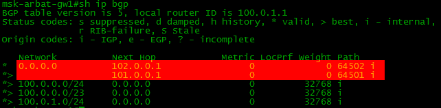
balagan-router(config-router)#neighbor 101.0.0.2 default-originate And this is how the route table on our border looks after this:
That is, in addition to the normal routes (Full View), the default route is also transmitted.
Now you should start to guess that the Default Route is not the opposite of Full View. It is not necessarily worth “either one or the other” (one should introduce the concept of healers or xyls, like the English XOR), you can easily use the Default Route in addition to the Full View or Default Route and some of some other routes.
=====================
Problem number 2Scheme: General Network Diagram
The task:
Set up filtering by the provider so that it passes us only the default route and nothing superfluous.
That is, to make the BGP table look like this:
Details of the task on the site
=====================
The benefits and harms of the complete BGP table
Looking Glass and other tools
One of the very powerful tools for working with BGP is Looking Glass. These are servers located on the Internet that allow you to look at the network from the outside: check availability, view through which AS the path to your autonomous system lies, start tracing to your internal addresses.

It’s as if you asked someone to “listen, but see how my announcements are seen there?”, But you don’t need to ask anyone.
Do not underestimate the power of external tools. Once I had a problem with a very low rate of return to the outside. She barely passed for a few megabits. After a rather lengthy troubling event, I decided to take a look at Looking Glass. What was my surprise when I discovered that the traffic was coming to me through a VPN channel to a branch in another city, with which IBGP is installed. Naturally, the width of the channel was small and was utilized almost completely.
There are also special organizations that track BGP announcements on the Internet and, if something unexpected happens, can notify the network owner - BGPMon , Renesys , RouterViews .
Thanks to them, several global accidents were prevented.
Using the BGPlay service, you can visualize route propagation information.
On nag.ru you can read about the most striking cases when incorrect BGP announcements caused global problems on the Internet, such as “AS 7007 Incident” and “Google's May 2005 Outage”.
Very good article on a variety of great tools for working with BGP.
The list of servers Looking Glass .
Control Plane and Data Plane
Before plunging into the deep pool of route management, let's make the last lyrical digression. It is necessary to understand the concepts in the title of the chapter.
At one time, while reading the MPLS Enabled Application , I broke my brain on them. Just could not figure out what the authors are talking about.
So, so that there is no confusion with you.
These are not model levels, environment levels, or data transfer moments — this is a very abstract division.
The control level ( Control Plane ) is the work of service protocols providing conditions for data transfer.
For example, when BGP is launched, it runs through all its states, exchanges route information, and so on.
Or, in an MPLS network, LDP distributes labels to prefixes.
Or STP, exchanging BPDUs, builds an L2 topology.
These are all examples of Control Plane processes. That is, it is the preparation of the network for transmission - organization of switching, filling in the routing table.
Transmitting level ( Data Plane ) - the actual transfer of useful customer data.
It often happens that the data of two levels go in different directions, “towards each other”. So, BGP routes are sent from AS100 to AS200 so that AS200 can transfer data to AS100.
Moreover, at different levels there may be different paradigms of work. For example, in MPLS Data Plane is focused on creating a connection, that is, the data there is transmitted along a predetermined path - the LSP.
But this path itself is prepared according to standard IP laws - from host to host.
It is important to understand the purpose of levels and what is the difference.
For BGP this is a matter of principle. When you announce your routes, you are actually creating a path for incoming traffic . That is, routes come from you, and traffic to you.
Route selection
The situation with the routes we have this.
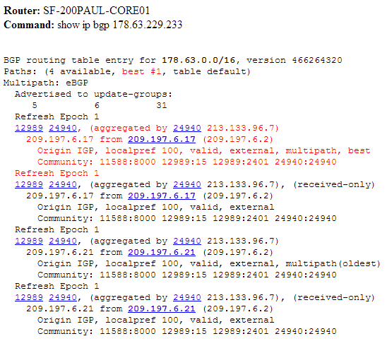
There is a BGP table in which absolutely all routes received from neighbors are stored.
 That is, if we have several routes to the network 100.0.0.0/23, then all of them will be in the BGP table, regardless of the “badness” of these:
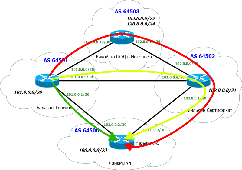
And there is a routing table familiar to us, storing only the best of the best. Likewise, BGP announces not all incoming routes, but only the best ones. That is, from one neighbor you will never get two routes to one network.
So, the criteria for choosing the best:
- Maximum Weight (local to router, for Cisco only)
- Maximum value of Local Preference (for the whole AS)
- Prefer local router route (next hop = 0.0.0.0)
- The shortest path through autonomous systems. (shortest AS_PATH)
- Minimum Origin Code (IGP
- The minimum value of MED (distributed between autonomous systems)
- EBGP path is better than iBGP path
- Choose a path through the nearest IGP neighbor
If this condition is met, the load is balanced between several equivalent links.
The following conditions may vary from vendor to vendor. - Choose the oldest route for the eBGP path
- Choose a path through the neighbor with the lowest BGP router ID
- Choose the path through the neighbor with the smallest IP address
As you can see, there are a lot of selection criteria. Moreover, they are quite complex and it is not easy to understand everything on the fly. Get involved slowly.
We will talk about some of the attributes mentioned below, and specifically on the choice of routes we will focus on a separate article.
=====================
Problem number 3Scheme: General Network Diagram
Condition: Full View on all routers
If you now look at the BGP table on the router of the provider Balagan Telecom, you will see 3 routes to the network 102.0.0.0/21 - the Filkin Certificate network. And one of the routes leads through our LinkMiAp network.

This suggests that our border announces other people's routes further, in other words, our AS is a transit one.
The task:
Set up filtering so that our AS64500 is no longer transit.
Details of the task on the site
=====================
Route management
Before moving on to the big topic of load sharing with BGP, it’s just necessary to figure out how we can manage routes in this protocol in general.
It is the ability of such management of routing information exchange that makes BGP so flexible and suitable for interaction between several different providers, unlike any IGP.
And we have a lot of tools for this:
- AS-Path ACL
- Prefix-list
- Weight
- Local Preference
- MED
But only the first two of them allow filtering routes that are advertised or accepted, the rest only set priorities.
AS-Path ACL
Very powerful, but not the most popular mechanism.
Using the AS-Path ACL, you can, for example, prohibit taking announcements of routes belonging to AS 200. Well, you just don’t want to - let them be known through another provider, but not through it.
The most difficult thing in this approach is to remember all regular expressions and learn how to use them. First, the head of them around:
| Sign | Value |
|---|---|
| . | any character including space |
| * | zero or more matches with expression |
| + | one or more matches with the expression |
| ? | zero or one match with expression |
| ^ | beginning of line |
| $ | end of line |
| _ | any separator (including, start, end, space) |
| \ | don't take the next character as special |
| [] | match one of the characters in the range |
| | | logical or |
To make it a little more clear, here are some examples:
one
| _200_ | Routes going through AS 200 |
Before and after the AS number there are “_” signs, meaning that the AS-path number 200 can stand at the beginning, middle or end, as long as it is.
2
| ^ 200 $ | Routes from the neighboring AS 200 |
“^” Means the beginning of the list, and “$” - the end. That is, in the AS-path there is only one AS number - this means that the route was originated in AS 200 and from there it was immediately transferred to us.
3
| _200 $ | Routes sent from AS 200 |
“$” Means the end of the list, that is, this is the very first AS, the route from it originated, the “_” sign says that it does not matter what is next, at least nothing, at least 7 other AS.
four
| ^ 200_ | Networks behind AS 200 |
The “^” sign means that the ASN 200 was last added, that is, the route came to us from AS 200, but this does not mean that he was born in it - the “_” sign indicates that this may be the end of the list, and maybe a space before the next AS.
five
| ^ $ | Local AS Routes |
The AS-path list is empty, so the route is local, generated inside our AS.
Example
Here in our network we will filter the routes that originated in AS 64501. That is, we will receive all Internet routes from our neighbor 101.0.0.1, but we will not receive their local ones.
ip as-path access-list 100 deny ^64501$ ip as-path access-list 100 permit .* router bgp 64500 neighbor 101.0.0.1 filter-list 100 in 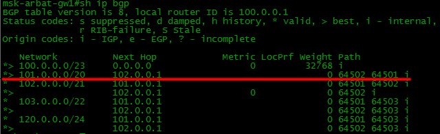 Device configuration
Instructions for using regular expressions
Prefix-list
Everything is simple and logical. Almost.
The prefix lists are simply the network / mask we are used to, and we specify to allow such routes or not.
Command syntax:
ip prefix-list {list-name} [seq {value}] {deny|permit} {network/length} [ge {value}] [le {value}] list-name - the name of the list. Your co. Usually specified as name_in or name_out . This prompts us to incoming or outgoing routes will act (but, of course, at this stage does not determine).seq - the ordinal number of the rule (as in the ACL) to make it easier to operate with them.
deny / permit - determine whether to allow such a route or not
network / length - the usual record for us, like, 192.168.14.0/24.
But further, attention is more complicated - two more parameters are possible: ge and le . As with the configuration of NAT (or in the FORP), this means " g reater or e qual" and " l ess or e qual".
That is, you can specify not only one specific prefix, but also their range.
For example, such a record
ip prefix-list NetDay permit 10.0.0.0/8 ge 10 le 16 will mean that the following routes will be chosen.
10.0.0.0/10, 10.0.0.0/11, 10.0.0.0/12, 10.0.0.0/13, 10.0.0.0/14, 10.0.0.0/15, 10.0.0.0/16
Example
Now we will forbid accepting the announcement of the network 120.0.0.0/24 through the provider of the Filkin Certificate, and allow all others. A record of 0.0.0.0/0 le 32 means any subnets with any mask length (less than or equal to 32 (0-32)).
ip prefix-list TEST_PL_IN seq 5 deny 120.0.0.0/24 ip prefix-list TEST_PL_IN seq 10 permit 0.0.0.0/0 le 32 router bgp 64500 neighbor 102.0.0.1 prefix-list TEST_PL_IN in 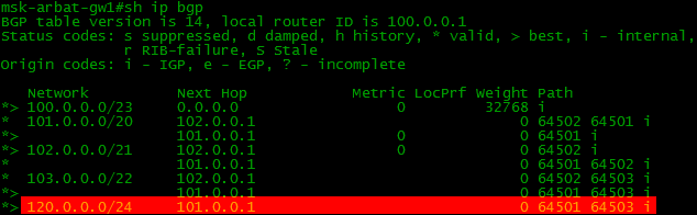
Let's make a reservation just in case: the last example does not mean that the neighboring provider will not transfer them to you - of course it will, because it knows nothing about your policies - but your router, having received such an announcement, will not add a route to its BGP - table.
Device configuration
Route map
Until now, all the rules were applied unconditionally - for all announcements from a feast or feast.
With the help of route maps (for other vendors, they may be called routing policies) we can apply the rules very flexibly, differentiating the announcements.
The command syntax is as follows:
route-map {map_name} {permit|deny} {seq} [match {expression}] [set {expression}] map_name - map namepermit / deny - allow or not the passage of data falling under the route-map conditions
seq - rule number in route-map
match - condition of traffic falling under this rule.
expression :
| Criterion | Configuration command |
|---|---|
| Network / mask | match ip address prefix-list |
| AS-path | match as-path |
| BGP community | match community |
| Route originator | match ip route-source |
| BGP next-hop address | match ip next-hop |
set - what to do with filtered
expression routes :
| Options | Configuration command |
|---|---|
| AS path prepend | set as-path prepend |
| Weight | set weight |
| Local Preference | set local-preference |
| BGP community | set community |
| MED | set metric |
| Origin | set origin |
| Bgp next-hop | set next-hop |
Application example
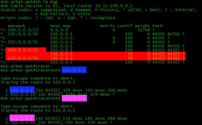
We indicate that it is preferable to go to the 120.0.0.0/24 subnet through the Filkin Certificate, and to 103.0.0.0/22 through the Balagan Telecom. To do this, use the attribute Local Preference. The higher the value of this parameter, the higher the priority of the route.
ip prefix-list TEST1_IN seq 5 permit 120.0.0.0/24 ip prefix-list TEST2_IN seq 5 permit 103.0.0.0/22 route-map BGP1_IN permit 10 match ip address prefix-list TEST1_IN set local-preference 50 route-map BGP1_IN permit 20 set local-preference 100 route-map BGP2_IN permit 10 match ip address prefix-list TEST2_IN set local-preference 50 route-map BGP2_IN permit 20 set local-preference 100 router bgp 64500 neighbor 101.0.0.1 route-map BGP2_IN in neighbor 102.0.0.1 route-map BGP1_IN in First, we created in the usual way the prefix-list , which was allocated the 120.0.0.0/24 subnet. Permit means that route-map rules will be applied to this prefix in the future. As with ordinary ACLs, there is an implicit deny rule for everything else. In this case, it means that only 120.0.0.0/24 and nothing else will fall under the route-map action.
In the BGP1_IN route map we created, we allowed the passage of route information ( permit ) falling under the created prefix-list ( match ip address prefix-list TEST1_IN ).
For these announcements, set the local preference to 50 - lower than the standard 100 ( set local-prefernce 50 ). That is, they will be less "interesting."
And in the end, we will bind the map to a specific BGP neighbor ( neighbor 102.0.0.1 route-map BGP1_IN in ).
What is the result?
 Device Configuration
Other examples will be discussed in the next section.
=====================
Task number 4Scheme: General network diagram
Condition: LinkMiAp receives Full View from both providers.
Subject: Troubleshooting.
From providers: complete BGP route table
On the msk-arbat-gw1 router, the distribution of outgoing traffic between providers of Balagan Telecom and Filkin Certificate is configured. The traffic going to the network of the provider of the Filkin Certificate must go through it if it is available. The rest of the outgoing traffic must be transmitted through the provider Balagan Telecom, when it is available.
When checking outgoing traffic, it turned out that when Balagan Telecom disconnects, outgoing traffic to the data center (103.0.0.1) does not go through the Filkin Certificate.
Configuration:
neighbor 102.0.0.1 route-map OUTBOUND in no auto-summary ! route-map OUTBOUND permit 10 match as-path 10 set weight 1000 ! ip prefix-list LAN permit 100.0.0.0/23 ! ip as-path access-list 10 permit ^64502$ ! ip route 100.0.0.0 255.255.254.0 Null0 The rest of the configuration is standard.
Task:
Correct the settings so that the outgoing traffic on the ISP2 network of the provider, to its client and to the network of the remote office of the company, goes through the ISP2 provider.
Details of the tasks on the site
=====================
Balancing and load balancing
“And how do you know how to balance traffic in BGP?”
This is a question that people like to ask during interviews.
Starting to prepare for this article, I had a conversation with our Natasha, from whom it became clear that in BGP, balancing and distribution are two big differences.
The division considered further is conditional and there are alternative views.
Load balancing
Balancing is usually understood as the distribution between several links of traffic directed to a single network.
It just turns on
router bgp 100 maximum-paths 2 The following conditions must be met:
- At least two routes in the BGP table for this network.
- Both routes go through the same provider.
- Weight, Local Preference, AS-Path, Origin, MED, IGP .
- Next Hop .
router bgp 64500 bgp bestpath as-path multipath-relax
AS-path, - .
How can we check it on our network? We need to make sure that balancing works.
Balancing is usually carried out on the basis of flows (IP address / port of the sender and IP address / port of the receiver) so that the packets arrive in the correct order. Therefore, we need to create two streams.
There is nothing simpler:
1) ping directly from msk-arbat-gw1 to 103.0.0.1
2) connect via telnet to msk-arbat-gw1 (remember to configure the parameters) from any other router and start ping with indication of the source (so that the streams will differed from each other)
After that, one ping will go through one link, and the second through another. Verified by
By default, the bandwidth of external channels is not taken into account. This feature is, however, implemented and launched by commands.
router bgp 64500 bgp dmzlink-bw neighbor 101.0.0.1 dmzlink-bw neighbor 102.0.0.1 dmzlink-bw Device configuration=====================
Task number 5Scheme: General network diagram
Condition: LinkMiAp receives the default route from both providers.
Task:
Configure outgoing traffic balancing between default routes from Balagan Telecom and Filkin providers in the proportion of 3 to 1.
Details of the task on the site
=====================
Load distribution
A completely different song with distribution is more fine-tuning the paths of outgoing and incoming traffic.
Outgoing
Outgoing traffic is sent in accordance with the routes received from above.
Accordingly, they should be managed.
Recall the scheme of our network.
So, there are the following ways:
1) Setting Weight. This is a tsiskovsky internal parameter — it is not transmitted anywhere — it works within the router. Other vendors also often have analogues (for example, Huawei's PreVal). There is nothing specific - we will not even stop. (default - 0)
Application to all routes received from a neighbor:
neighbor 192.168.1.1 weight 500 Application via route-map:
route-map SET_WEIGHT permit 10 set weight 500 ! router bgp 64500 neighbor 102.0.0.1 route-map SET_WEIGHT in 
2) Local Preference. This parameter is standard. The default is 100 for all routes. If you want to send traffic to certain subnets to certain links, then Local Preference is irreplaceable.
Above, we have already considered an example of using this parameter.
3) The aforementioned balancing with the maximum-paths
======================
Task number 6Scheme: General network diagram
Condition: LinkMiAp receives Full View from both providers.
Task:
Without using the weight, local preference or filtering attributes, configure the msk-arbat-gw1 router so that Balagan Telecom is the primary for outgoing traffic, and Filkin the Backup certificate.
Details of the task on the site
=====================
Incoming
It's all complicated.
The fact is that even with large providers, the outgoing traffic is insignificant in comparison with the incoming traffic. And there is so badly not noticed uneven distribution.
But if we are talking about Data Processing Centers or hosting providers, then the situation is reversed and the issue of balancing is very serious.
Here we are extremely constrained in the means:
1) AS-Path Prepend
One of the most frequent tricks is the “deterioration” of the path. It often happens that through one provider your routes will be transferred with an AS-path length longer than through the other. Of course, BGP chooses the first, categorically, and only through it will transmit traffic. To even out the situation when announcing routes, you can add an extra “hop” to the AS-Path.
And there is such a situation that one provider provides a wider channel for little money, but the path through it is longer and all traffic goes to the other - expensive and narrow. This situation is unprofitable for us and we would like the narrow channel to become a backup one.
Here it is and analyze. But you have to take a completely degenerate situation. For example, access from Balagan Telecom to LikMiAp network.
This is how the BGP table and routing on the Balagan Telecom provider usually look like:
If we want to worsen the main path (a direct link between them), then we need to add AS to the AS-Path list:
router bgp 64500 neighbor 101.0.0.1 route-map AS_PATH_PREP out route-map AS_PATH_PREP permit 10 set as-path prepend 64500 64500 Then the picture will look like this.
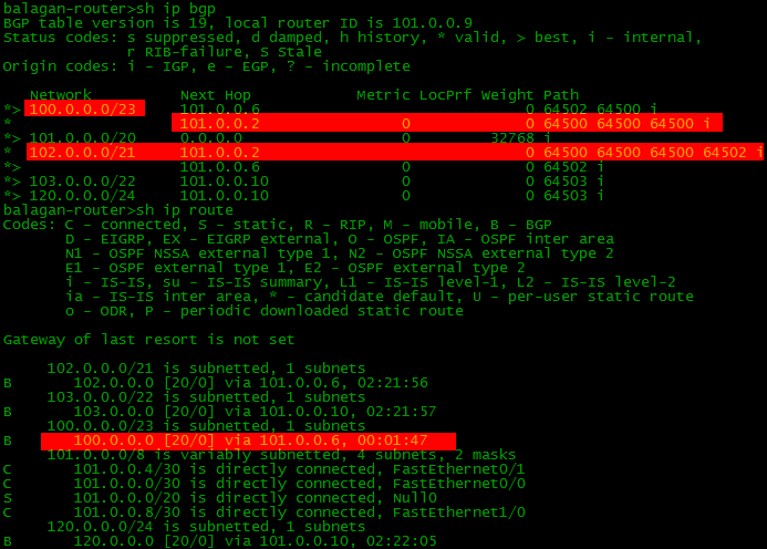
Of course, a path is chosen with a shorter AS-Path length, that is, via Filkin Certificate (AS6502)
This route is added to the routing table.
Note that it is usual to add your AS number to AS-Path. You can, of course, and someone else, but you will not understand in a decent society.
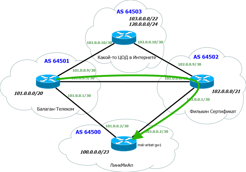
Thus, we have ensured that the traffic will go the way we planned.
Naturally, when one of the channels drops, the traffic will switch to the second, regardless of the AS-Path Prepend set up.
Device configuration .
2) MED
Multiexit Discriminator. In cisco, it is called a metric (Inter-AS metric). MED is a weak attribute. Weak, because it is checked only at the sixth step when choosing a route and has essentially a weak effect.
If the Local Preference affects the choice of the exit path of the traffic from the Autonomous System, then the MED is transmitted to the neighboring AS and thus affects the entry path of the traffic.
In general, MED and Local Preference are often confused by beginners, so we will describe the difference in the table.
| Local Preference | MED |
|---|---|
| Defines the priority of the path for traffic exit. | Defines the priority of the path for traffic entry. |
| Valid only within AS. It is not transmitted to other AS. | It is transmitted to other AS and hints through which path to transmit traffic is preferable. |
| It can work when connecting to different AS | It works only with multiple connections to one AS. |
| The higher the value, the higher the priority. | The higher the value, the lower the priority. |
We will not dwell on it, because they rarely use it, and our network is not suitable for this - there should be several connections between two AS, and we only have one in each.
3) Announcement of different prefixes through different ISPs
Another way to distribute the load is to distribute different networks to different providers.
Now in the data center network, our announcements look like this:

That is, our network 100.0.0.0/23 is known through two paths, but only one will be added to the routing table. Accordingly, all traffic back will go one - the best way.
But!
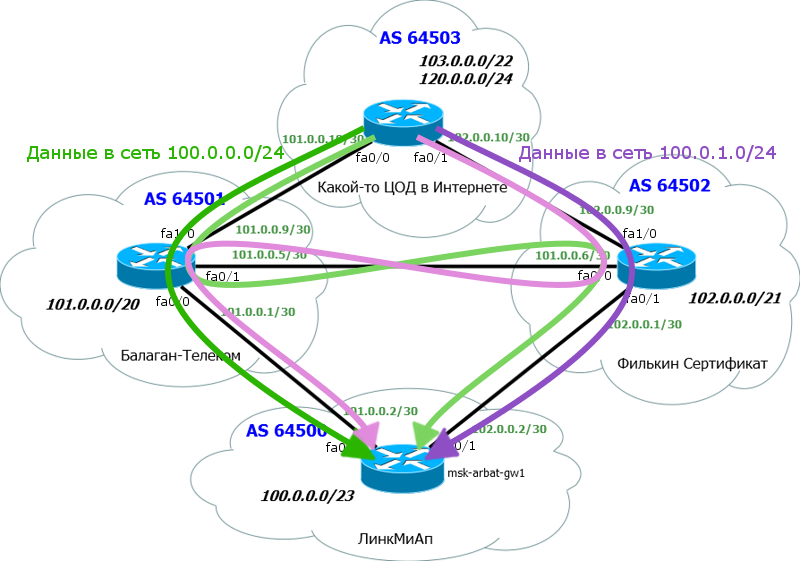
We can divide it into two / 24 subnets and send one to Balagan Telecom, and another to Filkin Certificate.
Accordingly, the data center will know about these subnets through different paths: It is
configured this way.
First, we register all our subnets - all 3: one large / 23 and two small / 24:
router bgp 64500 network 100.0.0.0 mask 255.255.254.0 network 100.0.0.0 mask 255.255.255.0 network 100.0.1.0 mask 255.255.255.0 In order for them to be announced, you need to create routes to these subnets.
ip route 100.0.0.0 255.255.254.0 Null0 ip route 100.0.0.0 255.255.255.0 Null0 ip route 100.0.1.0 255.255.255.0 Null0 And now we create prefix-lists, which allow each only one subnet / 24 and common / 23.
ip prefix-list LIST_OUT1 seq 5 permit 100.0.0.0/24 ip prefix-list LIST_OUT1 seq 10 permit 100.0.0.0/23 ! ip prefix-list LIST_OUT2 seq 5 permit 100.0.1.0/24 ip prefix-list LIST_OUT2 seq 10 permit 100.0.0.0/23 It remains to attach the prefix lists to the neighbors.
router bgp 64500 neighbor 101.0.0.1 remote-as 64501 neighbor 101.0.0.1 prefix-list LIST_OUT1 out neighbor 102.0.0.1 remote-as 64502 neighbor 102.0.0.1 prefix-list LIST_OUT2 out We tie them to OUT - to outgoing, because we are talking about routes that we send outside.
So, we will announce the neighbor 101.0.0.1 (Balagan Telecom) networks 100.0.0.0/24 and 100.0.0.0/23.
And the neighbor 102.0.0.1 (Filkin Certificate) - networks 100.0.1.0/24 and 100.0.0.0/23.
The result will be:
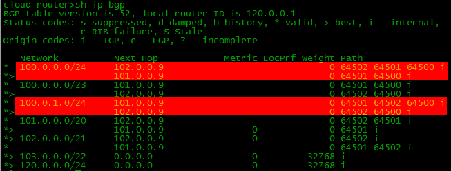
It seems to be wrong, because we have two routes to each network / 24 - through Balagan Telecom and through the Filkin Certificate.
But if you look closely, you will see that according to AS-Path we have such routes:
That is, in fact, everything is correct. Yes, and in the routing table, everything fits correctly:
Now it remains to answer the question of the devil, we dragged a large subnet / 23? After all, according to the rule of Longest prefix match, more accurate routes are preferable, that is / 23, as if not needed when there is / 24.
But let us imagine a situation when the Balagan Telecom network falls. What happens? Subnet 100.0.0.0/24 will cease to be known on the Internet - after all, only Balagan Telecom knew something about it thanks to our configuration. Accordingly, part of our network will fall. But!We are saved by a more general route 100.0.0.0/23. Filkin Certificate knows about it and announces it on the Internet. Accordingly, although the data center does not know about the network 100.0.0.0/24, it knows about 100.0.0.0/23 and will allow traffic in the direction of the Filkin Certificate.

That is, thank Leibniz, we are insured against such a situation.
, RIPE. /24 /23.
4) BGP Community
With the help of the BGP Community, you can give the provider instructions on what to do with the prefix, to whom to transfer, to whom it is not, what local preference to set, and so on. We will not consider this option now, because we will move the topic of the community to the next issue.
=====================
Task number 7Scheme: General network diagram
Condition: The router msk-arbat-gw1 is configured to control incoming and outgoing traffic. The main provider Balagan Telecom, reserve - Filkin Certificate. When checking the settings, it turned out that the outgoing traffic is transmitted correctly. When checking incoming traffic, it turned out that incoming traffic also goes through the provider Balagan Telecom, but when Balagan Telecom is disconnected, the incoming traffic does not go through the Filkin Certificate.
Task: Correct the settings.
Configuration:
hostname msk-arbat-gw1 ! interface Loopback0 ip address 100.0.0.1 255.255.255.255 ! interface FastEthernet0/0 description Balagan_Telecom_Internet ip address 101.0.0.2 255.255.255.252 duplex auto speed auto ! interface FastEthernet0/1 description Philkin_Certificate_Internet ip address 102.0.0.2 255.255.255.252 speed 100 full-duplex ! router bgp 64500 no synchronization bgp log-neighbor-changes network 100.0.0.0 mask 255.255.254.0 neighbor 101.0.0.1 remote-as 64501 neighbor 101.0.0.1 prefix-list LAN out neighbor 101.0.0.1 weight 500 neighbor 102.0.0.1 remote-as 64502 neighbor 102.0.0.1 prefix-list LAN out neighbor 102.0.0.1 route-map INBOUND out no auto-summary ! route-map INBOUND permit 10 set as-path prepend 64502 64502 64502 ! ip prefix-list LAN permit 100.0.0.0/23 ! ip route 100.0.0.0 255.255.254.0 Null0 Details of the tasks on the site
=====================
Instructions on the types of balancing and load distribution
Natasha Samoylenko - the author of xgu.ru prepared a presentation for us.
You can download it and use it as you wish, indicating the authorship.
PBR
All the routing technologies that we used up to this point in our articles, whether static routing, dynamic routing (IGP or EGP), took into account only one sign of the packet: the destination address. All of them, simply, acted on the same principle: they looked where the packet went, found the most specific route to the destination (longest match) in the routing table, and forwarded the packet to the interface that was recorded in the table opposite this very route. This, in general, is the essence of routing. And what if this order of things does not suit us? What if we want to route a packet, starting from the source address? Or do we need the HTTP
In such a situation, policy-based routing aka PBR (Policy based routing) comes to the rescue. This technology allows us to manage traffic based on the following features of the package:
- Source address (or a combination of source address and recipient address)
- Information level 7 (applications) OSI
- The interface to which the packet came
- QoS tags
- Generally speaking, any information used in the extended-ACL (source / destination port, protocol, etc., in any combination). Those. if we can isolate the traffic we are interested in using an extended ACL, we will be able to route it as we please.
The benefits of using PBR are obvious: incredible routing flexibility. But the minuses are also present:
- All you need to write with your hands, hence a lot of work and the risk of error
- Performance. On most hardwares, PBR is slower than regular routing (with the exception of Catalysts 6500, they have a supervisor with iron support for PBR)
The policy based on which PBR is implemented is created with the route map POLICY_NAME command , and contains two sections:
- Allocation of the necessary traffic. It is carried out either by means of ACL, or depending on the interface in which the traffic came. The match command in the route map configuration mode is responsible for this.
- Apply action to this traffic. The set command is responsible for this.
We have a bit of practice to do this. We have this topology:
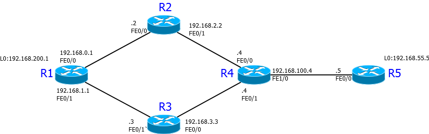
At the moment, R1-R5 traffic and back goes along the route R1-R2-R4-R5, for convenience, the addresses are assigned so that the last digit of the address is the router number:
R1 # traceroute 192.168.100.5
1 192.168.0.2 20 msec 36 msec 20 msec
2 192.168.2.4 40 msec 44 msec 16 msec
3 192.168.100.5 56 msec * 84 msec
R5 # traceroute 192.168.0.1
1 192.168.100.4 56 msec 40 msec 8 msec
2 192.168.2.2 20 msec 24 msec 16 msec
3 192.168.0.1 64 msec * 84 msec
For example, suppose we need to return traffic from R5 (with its source address) along the route R5-R4- R3 -R1 . According to the scheme, it is obvious that the decision on this should take R4. On it, we first create an ACL that selects the packets we need:
R4(config)#access-list 100 permit ip host 192.168.100.5 any Then create a routing policy with the name “BACK”:
R4(config)#route-map BACK Inside it we say what traffic we are interested in:
R4(config-route-map)#match ip address 100 And what to do with it:
R4(config-route-map)#set ip next-hop 192.168.3.3 After that we go to the interface that looks towards R5 (PBR works with incoming traffic!) And apply the resulting policy on it:
R4(config)#int fa1/0 R4(config-if)#ip policy route-map BACK Checking:
R5 # traceroute 192.168.0.1
1 192.168.100.4 40 msec 40 msec 16 msec
2 192.168.3.3 52 msec 52 msec 44 msec
3 192.168.1.1 56 msec * 68 msec
Works! And now let's look carefully at the scheme and think: is everything ok?
And no!
Following this ACL, at us all traffic with a source of R5 is turned on R3. This means that if, for example, R5 wants to get to R2, it will, instead of the short and obvious route R5-R4-R2, be sent along the route R5-R4-R3-R1-R2. Therefore, it is necessary very carefully and thoughtfully to make ACL for PBR, making it as specific as possible.
In this example, we have chosen to redefine the nextop (the network node where the packet will go further) as the action applied to the traffic. What else can you do with PBR? Available commands:
- set ip next-hop
- set interface
- set ip default next-hop
- set default interface
With the first two, everything is relatively clear - they override the nextop and the interface from which the packet will exit (most often the set interface is used for point-to-point links). And if we use the set ip default next-hop or set default interface commands , the router first looks at the routing table, and if there is a route for the packet being checked, sends it accordingly to the table. If there is no route, the packet is sent as stated in the policy. For example, if we in our topology instead of set ip next-hop 192.168.3.3 had commanded set ip default next-hop 192.168.3.3, nothing would have changed, since R4 has a route to R1 (via R2). But if he was absent, the traffic would be directed to R3.
, set : QoS MPLS BGP
=====================
Task number 8Condition: LinkMiAp uses static routes to providers (not BGP).
Scheme and configuration . Provider routers also do not use BGP.
Task: Set up switching between providers.
The default route to Balagan Telecom should be used as long as the icmp responses to google ping (103.0.0.10) OR yandex (103.0.0.20) arrive. Requests should be sent via Balagan Telecom. If none of the specified resources responds, the default route should switch to the provider of the Filkin Certificate. In order for switching not to occur due to the temporary loss of individual icmp responses, it is necessary to set a switching delay of at least 5 seconds.
Details of the taskhere
=====================
IP SLA
And now the tastiest: imagine that in our scheme, the main path R4-R2-R1 is served by one provider, and the spare one R4-R3-R1 is another. Sometimes the first provider has load problems that cause our voice traffic to start to suffer. At the same time, another route is not loaded and it would be good to transfer the voice to it at this moment. Ok, we write route map, as we did above, which allocates voice traffic and directs it through a normally working provider. And then - op, the situation has changed to the opposite - again, everything has to be changed back. Weekdays technical support: "And such rubbish all day: either a seal calls, or a deer." But it would be cool if we could track the characteristics of the main channel we need (for example, delay or jitter), and, depending on their value,automatically send voice or video on the main or backup channel, right? So, miracles happen. In our case, the miracle is called IP SLA.
This technology, in fact, is active network monitoring, i.e. generating some traffic in order to evaluate one or another characteristic of the network. But monitoring does not end there - the router can, using the data obtained, influence the decision making on routing, thus reacting and solving the problem. For example, unload the busy channel, distributing the load on others.
Without further ado, immediately to the setting. First, we need to say that we want to monitor. Create a monitoring object, assign it a number:
R4(config)#ip sla 1 So, what can we monitor here?
R4(config-ip-sla)#?
IP SLAs entry configuration commands:
dhcp DHCP Operation
dns DNS Query Operation
exit Exit Operation Configuration
frame-relay Frame-relay Operation
ftp FTP Operation
http HTTP Operation
icmp-echo ICMP Echo Operation
icmp-jitter ICMP Jitter Operation
mpls MPLS Operation
path-echo Path Discovered ICMP Echo Operation
path-jitter Path Discovered ICMP Jitter Operation
slm SLM Operation
tcp-connect TCP Connect Operation
udp-echo UDP Echo Operation
udp-jitter UDP Jitter Operation
voip Voice Over IP Operation
, , IP SLA, : IOS 12.4(4)T , , . , ip sla 1 rtr 1 ip sla responder – rtr responder
As you can see, the list is impressive, so we will not stop, for those interested, there is a detailed article on tsisko.com.
=====================
Task number 9Condition: LinkMiAp uses static routes to providers (not BGP).
Scheme and configuration . Provider routers also do not use BGP.
Task:
Configure routing so that HTTP traffic from the local 10.0.1.0 network goes through Balagan Telecom, and all traffic from the 10.0.2.0 network through the Filkin Certificate. If any other address appears in the sender's address, the traffic should be dropped, and not routed through the standard routing table (the task must be completed without filtering using ACLs applied on the interface).
Additional condition: PBR rules should work this way only if the relevant provider is available (for this task, it is sufficient to check the availability of the nearest provider device). Otherwise, a standard routing table should be used.
Details of the task here
=====================
Usually, IP SLA work is considered on the simplest example icmp-echo . That is, in case we can ping that end of the line, the traffic goes on it, if we cannot, on the other. But we will go a little more difficult. So, we are interested in the characteristics of the channel, important for voice traffic, for example, jitter. More specifically, udp-jitter , so we write
R4(config-ip-sla)#udp-jitter 192.168.200.1 55555 In this command, after specifying the type of verification ( udp-jitter ), the ip address goes to where the samples will be sent (ie, we measure from us to 192.168.200.1 - this is a loopback on R1) and the port (from bald 55555 ). Then you can set the check frequency (by default 60 seconds):
R4(config-ip-sla-jitter)#frequency 10 and the limit value, above which the ip sla 1 object reports unavailability:
R4(config-ip-sla-jitter)#threshold 10 Some types of measurements in IP SLA require the presence of a so-called “responder” on the “other side” (responder), some (for example, FTP, HTTP, DHCP, DNS) do not. Our udp-jitter requires, therefore, before you run the measurements, you need to prepare R1:
R1(config)#ip sla responder Now we need to start collecting statistics. Commanding
R4(config)#ip sla schedule 1 start-time now life forever Those. We start the monitoring object 1 right now and until the end of days.
We cannot change object parameters if statistics collection is running. Those.to change, for example, the frequency of samples, we need to first turn off the collection of information from it: no ip sla schedule 1
Now we can see what we have there going:
R4#sh ip sla statistics 1
Round Trip Time (RTT) for Index 1
Latest RTT: 36 milliseconds
Latest operation start time: *00:39:01.531 UTC Fri Mar 1 2002
Latest operation return code: OK
RTT Values:
Number Of RTT: 10 RTT Min/Avg/Max: 19/36/52 milliseconds
Latency one-way time:
Number of Latency one-way Samples: 0
Source to Destination Latency one way Min/Avg/Max: 0/0/0 milliseconds
Destination to Source Latency one way Min/Avg/Max: 0/0/0 milliseconds
Jitter Time:
Number of SD Jitter Samples: 9
Number of DS Jitter Samples: 9
Source to Destination Jitter Min/Avg/Max: 0/5/20 milliseconds
Jitter Min / Avg / Max: 0/16/28 milliseconds
Packet Loss Values:
Loss Source to Destination: 0 Loss Destination to Source: 0
Out Of Sequence: 0 Tail Drop: 0
Packet Late Arrival: 0 Packet Skipped: 0
Voice Score Values:
Calculated Planning Impairment Factor (ICPIF): 0
Mean Opinion Score (MOS): 0
Number of successes: 12
Number of failures: 0
Operation time to live: Forever
and what we have configured there
R4#sh ip sla conf
IP SLAs Infrastructure Engine-II
Entry number: 1
Owner:
Tag:
Type of operation to perform: udp-jitter
Target address/Source address: 192.168.200.1/0.0.0.0
Target port/Source port: 55555/0
Request size (ARR data portion): 32
Operation timeout (milliseconds): 5000
Packet Interval (milliseconds)/Number of packets: 20/10
Type Of Service parameters: 0x0
Verify data: No
Vrf Name:
Control Packets: enabled
Schedule:
Operation frequency (seconds): 10 (not considered if randomly scheduled)
Next Scheduled Start Time: Pending trigger
Group Scheduled: FALSE
Randomly Scheduled: FALSE
Life (seconds): 3600
Entry Ageout (seconds): never
Recurring (Starting Everyday): FALSE
Status of entry (SNMP RowStatus): Active
Threshold (milliseconds): 10
Distribution Statistics:
Number of statistic hours kept: 2
Number of statistic distribution buckets kept: 1
Statistic distribution interval (milliseconds): 4294967295
Enhanced History:
Now we are setting up the so-called track (incorrect but understandable translation “tracker”). It is to his condition that actions in route map are subsequently attached. In the track, you can set the delay of switching between states, which allows you to solve the problem, when we have the routing change for one unsuccessful sample, and the next, already successful one, changes back. We specify the track number and to which ip sla object number we connect it (rtr 1):
R4(config)#track 1 rtr 1 Configuring the delay:
R4(config-track)#delay up 10 down 15 This means: if the monitoring object fell and did not rise within 15 seconds, we move the track to the down state . If the object was able to down, but rose and is in the raised state for at least 10 seconds, we translate the track into the up state .
The next step is to link the track to our route map. Let me remind you that the standard path from R5 to R1 goes through R2, but we have a route-map BACK reassigning the standard state of affairs in case the source is R5:
R4 # sh run | sec route-map
ip policy route-map BACK
route-map BACK permit 10
match ip address 100
set ip next-hop 192.168.3.3
If we tie our monitoring to this map, replacing the set ip next-hop 192.168.3.3 command with set ip next-hop verify-availability 192.168.3.3 10 track 1 , we get the opposite effect: in case of a fall of the track (due to jitter in sla 1), the map will not be processed (everything will go according to the routing table), and vice versa, in the case of normal values, the track will be up, and traffic will go through R3.
How it works: the router sees that the packet falls under the match conditions, but then does not immediately set, as in the previous example with PBR, and first checks the status of track 1, and then, if it is raised (up), set is already done if not, go to the next line of the route map.
In order for our map to work as it should, we need to somehow invert the value of the track, i.e. when jitter is big, our track should be UP, and vice versa. This will help us such a thing as track list. In IP SLA, it is possible to combine in the track a list of other tracks (which, in essence, give 1 or 0 at the output) and perform logical operations OR or AND on them, and the result of these operations will be the status of this track. In addition, we can apply logical negation to the state of the track. Create a track list:
R4(config)#track 2 list boolean or The only thing in this “list” will be the logical negation of the value of track 1:
R4(config-track)#object 1 not Now we attach a route map to this track.
R4(config)#route-map BACK R4(config-route-map)#no set ip next-hop 192.168.3.3 R4(config-route-map)#set ip next-hop verify-availability 192.168.3.3 10 tr 2 The number 10 after the address of the nextop is its sequence number. We can, for example, use it like this:
route-map BACK permit 10 match ip address 100 set ip next-hop verify-availability 192.168.3.3 <b>10</b> track 1 set ip next-hop verify-availability 192.168.2.2 <b>20</b> track 2 There is such logic: choose the traffic falling under ACL 100, then there is an intermediate test of track 1, if it is up, we set the package to a nextop 192.168.3.3, if down, we go to the next sequence number (20 in this case), again we check the status track (already another, 2), depending on the result, set a nextop 192.168.2.2 or send with the world (routed on a common basis).
Let's now talk a little bit about what we have done: so, jitter measurements go from source R4 to responder R1 along the route through R2. The maximum permissible jitter value on this route is 10. In case jitter exceeds this value and stays at this level for 15 seconds, we switch traffic generated by R5 to route through R3. If the jitter falls below 10 and stays there for at least 10 seconds, let the traffic from R5 follow the standard route. Try to fix the material to find which commands specify all these values.
So, we have reached the goal: now, in case of deterioration in the quality of the main channel (well, at least, the values of udp-jitter), we are switching to the backup one. But what if there is also not very? Maybe try using IP SLA to solve this problem?
Let's try to build the logic of what we want to do. Before switching to the backup channel, we want to check how we deal with jitter on it. To do this, we need to have an additional monitoring object that will consider the jitter on the path R4-R3-R1, let it be 2. Let's make it similar to the first one, with the same values. The condition for switching to the backup channel will then be: object 1 down And object 2 up. To measure non-mainstream jitter, you will have to use a trick: make loopback interfaces on R1 and R4, set up static routes through R3 back and forth, and use these addresses for the SLA 2 object.
R1(config)#int lo1 R1(config-if)#ip add 192.168.30.1 255.255.255.0 R1(config-if)#exit R1(config)#ip route 192.168.31.0 255.255.255.0 192.168.1.3 R3(config)#ip route 192.168.30.0 255.255.255.0 192.168.1.1 R3(config)#ip route 192.168.31.0 255.255.255.0 192.168.3.4 R4(config)#int lo0 R4(config-if)#ip add 192.168.31.4 255.255.255.0 R4(config-ip-sla-jitter)#exit R4(config)#ip sla 2 R4(config-ip-sla)#udp-jitter 192.168.30.1 55555 source-ip 192.168.31.4 R4(config-ip-sla-jitter)#threshold 10 R4(config-ip-sla-jitter)#frequency 10 R4(config-ip-sla-jitter)#exit R4(config)#ip route 192.168.30.0 255.255.255.0 192.168.3.3 R4(config)#ip sla schedule 2 start-time now life forever R4(config)#track 3 rtr 2 Now we change the condition of track 2, to which the route map is attached:
R4(config)#track 2 list boolean and R4(config-track)#object 1 not R4(config-track)#object 3 Voila, now R5-> R1 traffic switches to the spare route only if the jitter of the main channel is more than 10 and, at the same time, the spare jitter is less than 10. In case high jitter is observed on both channels, the traffic goes through the main and silently suffers.
The state of the track can also be tied to a static route: for example, we can use ip route 0.0.0.0 0.0.0.0 192.168.1.1 track 1 to make the default gateway 192.168.1.1, which will be associated with track 1 (which, in turn, can check the presence of this very 192.168.1.1 in the network or measure any important characteristics of the quality of communication with it). In case the connected track falls, the route is removed from the routing table.
It will also be useful to mention that the information received via IP SLA can be pulled out via SNMP so that it can be stored and analyzed somewhere in your monitoring system later. You can even configure SNMP traps.
=====================
Task number 10Scheme: as in other tasks for PBR. Configuration below.
Condition: LinkMiAp uses static routes to providers (not BGP). PBR is configured
on the msk-arbat-gw1 router : HTTP traffic must go through the provider Filkin Certificate, and traffic from the 10.0.2.0 network must go through Balagan Telecom.
The specified traffic is transmitted correctly, but the rest of the traffic from the local network, which must be transmitted through the provider Balagan Telecom, is not routed.
Task:
Correct the settings so that they meet the conditions.
Configuration:
=====================
eucariot thegluck
. hostname msk-arbat-gw1 interface Loopback1 ip address 10.0.1.1 255.255.255.0 ip nat inside ! interface Loopback2 ip address 10.0.2.1 255.255.255.0 ip nat inside ! interface FastEthernet0/0 description Balagan_Telecom_Internet ip address 101.0.0.2 255.255.255.252 ip nat outside duplex auto speed auto ! interface FastEthernet0/1 description Philkin_Certificate_Internet ip address 102.0.0.2 255.255.255.252 ip nat outside speed 100 full-duplex ! ! ip access-list extended LAN permit ip 10.0.1.0 0.0.0.255 any permit ip 10.0.2.0 0.0.0.255 any ! route-map BALAGAN permit 10 match ip address LAN match interface FastEthernet0/0 route-map PH_CERT permit 10 match ip address LAN match interface FastEthernet0/1 ! ip nat inside source route-map BALAGAN interface Fa0/0 overload ip nat inside source route-map PH_CERT interface Fa0/1 overload ! ip access-list extended HTTP permit tcp any any eq 80 ! ip access-list extended LAN2 permit ip 10.0.2.0 0.0.0.255 any ! route-map PBR permit 10 match ip address HTTP set ip next-hop 102.0.0.1 route-map PBR permit 20 match ip address LAN2 set ip next-hop 101.0.0.1 ! ip local policy route-map PBR =====================
useful links
Bgp
- BGP
- ,
- BGP
- LIR, RIR
- FAQ
- BGP
- AS-PATH ACL , AS-PATH Prepend , Load Balancing , Load Sharing Prefix List , Prefix List , Route Map
IP SLA
eucariot thegluck
Thanks for the help JDima .
Problems we wrote an incomparable Natasha Samoilenko .
The cycle “Networks for the smallest” has its own website: linkmeup.ru , where you can find all the issues neatly folded and ready for thoughtful reading.
Source: https://habr.com/ru/post/184350/
All Articles