Mobile Backhaul for a small mobile operator
Good afternoon, dear community.
In this article I would like to tell you a little about the planning of Mobile Backhaul in our small telecom operator. Perhaps someone will find it interesting, and maybe useful.
To begin with, our company provides 2G / 3G mobile services and plans to launch LTE in commerce in the near future. Our subscriber base is only about 200,000 people. Thus, by modern standards, we are a fairly small operator.
')
And so, not so long ago, we were faced with the task of modernizing the core data network.
As is known, at present, many telecom operators are transferring their backbone networks to IP.
This is due to the increase in the volume of consumed traffic, the introduction of new technologies such as VoIP, IPTV, LTE, etc.
The transition to IP makes the operator very flexible, allows you to easily increase bandwidth and provide new services.
Our operator was no exception, and we also launched the Mobile Backhaul project.
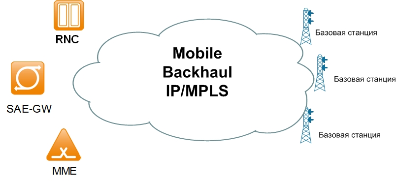
Mobile Backhaul is a backbone data network connecting base stations with functional elements of a 2G / 3G / LTE network (base station controllers, etc.). And in the case of LTE Mobile Backhaul also provides the ability to connect base stations directly to each other. In addition, Mobile Backhaul should also provide the possibility of providing all the necessary services (synchronization, quality of service, etc.).
At the first stage, it was necessary to understand what requirements the backbone network should meet and what equipment should be used for this.
After analyzing the tasks we have, it was found that the core network should perform the following functions:
1) Provide the ability to isolate various types of traffic from the base station (signaling, control, data, etc.)
2) Provide the ability to connect corporate customers using L2VPN / L3VPN service
3) Provide the necessary indicators of quality of service (QoS)
4) Provide the ability to synchronize base stations over IP (IEEE 1588)
Thus, taking into account these requirements, it was decided to deploy MPLS technology in the core network, which allows implementing all (and even more) of the above functions on top of oneself.
To build Mobile Backhaul, Cisco Systems equipment was selected.
The choice was made taking into account the following factors:
1) Our operator has a long-standing relationship with Cisco Systems. The entire transport network is built on the equipment of this company.
2) The technology network uses Nokia equipment, which is a partner of Cisco Systems in building networks for telecom operators.
3) Recently, Cisco has released a sufficient amount of interesting hardware for telecom operators that fits very well with our concept.
Currently, both Nokia and Cisco Systems have many options for carrier network design. The main problem in our case was that all these options were planned for large operators and did not meet our requirements.
In particular, Cisco offers the Unified MPLS Mobile Transport Design Guide (which is freely available on the Cisco Community site) for designing the core network. In this Design Guide there are several options for building a network, the minimum of which provides for a situation in which you have “less than 1000 access nodes”. And even this option turned out to be large for our operator (initially it is planned to transfer about 50 base stations to IP with a further increase to 300-400). In this case, several nearby base stations can be connected to one access node.
Thus, in our network, you can count on a maximum of 100-150 access nodes.
In connection with the foregoing, we have begun to simplify the scheme proposed by Cisco and adaptation to our realities.
The result was the following:
1) The core network will consist of three levels: access, aggregation, and core (for large solutions, Cisco uses 5 levels).
2) MPLS will be configured on the entire core network, up to access. This will allow us to implement all the necessary functionality and provide the required level of service.
3) Routing will also be reached to the access nodes, which will allow to transfer traffic between neighboring base stations directly, bypassing the aggregation / core.
Cisco ASR901 routers, positioned as Cell Site Gateway, were chosen as access points.
The advantages of these routers are: relatively low price, a full set of necessary functions, DC power, low power consumption and a large set of network interfaces.
Cisco ME3600X switches were chosen as aggregation nodes. These switches have 24 Gigabit Ethernet optical ports and two 10 Gigabit interfaces, which allow large amounts of traffic to be sent to the core. In addition, these switches support MPLS well and all the necessary functions.
The core of the backbone network is the currently available Cisco 7609. For them, only 10 Gigabit boards were purchased to provide the necessary bandwidth.
As a result, the following scheme emerges:
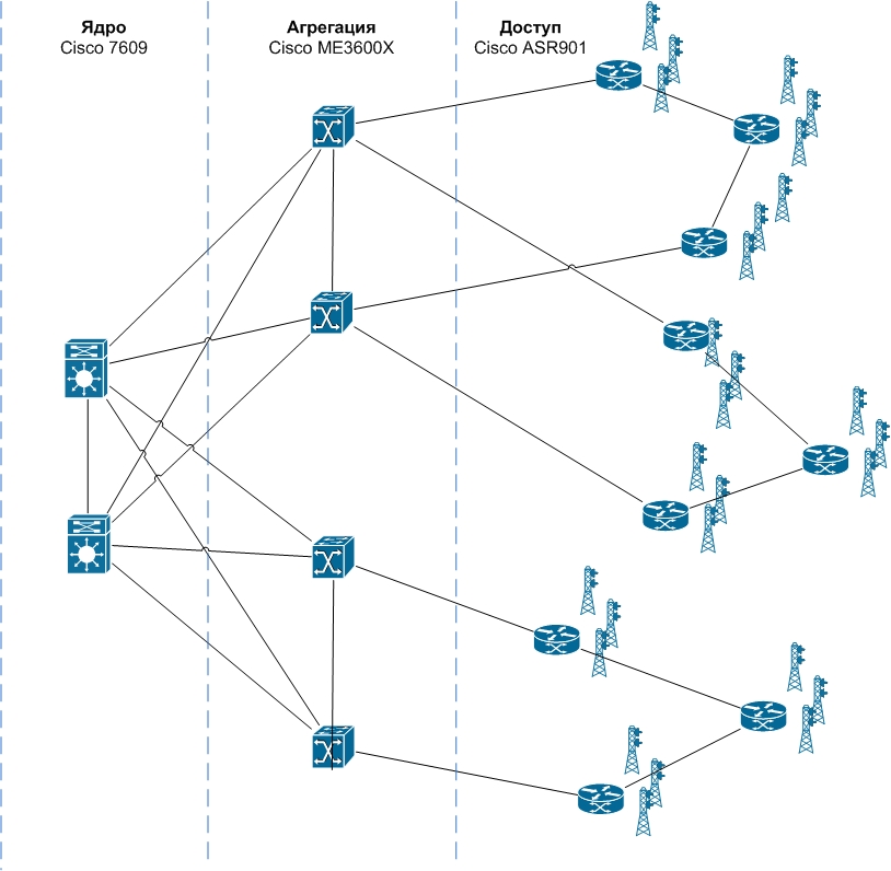
All access nodes are connected by a semi-ring of 3-5 routers, which saves costly ports on the aggregation switches and at the same time provides redundancy in case of a single device or link failure. Each of the aggregation nodes is connected to each of the kernel nodes, which also provides the necessary level of redundant.
In our case, there are two types of connection: 2G / 3G stations and LTE stations.
In the case of LTE, everything looks pretty simple. IP / MPLS extends up to ASR901. On the ASR 901, the OSPF routing protocol and the necessary L3VPN (VRF) are configured - in our case, these are ControlPlane, UserPlane, O & M and SyncroPlane:
ControlPlane - Alarm
UserPlane - Data
O & M - Management
SyncroPlane - Sync
Base stations are switched by various subinterfaces into the L3VPN they need.
The same L3VPNs are present on the nodes to which the MSS / RNC and others are connected. Thus, the connection between the base station and the specified network elements is carried out in isolation inside the L3VPN via the MP-BGP protocol.

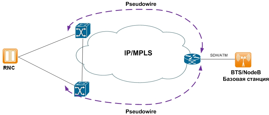
In the case of 2G / 3G base stations are connected using TDM / ATM, through which data and service traffic are transmitted. In this regard, it is necessary to ensure the transfer of TDM / ATM traffic between the base station and the controller over the IP network. This is achieved by configuring L2VPN (Pseudowire) between the ASR901 and the site switches to which the RNC is connected. Thus, all data is transmitted over the tunnel over the IP network.
As a result, we get a unified architecture that allows you to connect various types of base stations, corporate clients and which at the same time easily scales.
This scheme in test use has proven itself very well and is preparing to enter into commercial operation.
In order not to overload the article, the issues of QoS, synchronization, etc. were not deeply affected.
Perhaps these questions will be described further if they are of interest to anyone.
In this article I would like to tell you a little about the planning of Mobile Backhaul in our small telecom operator. Perhaps someone will find it interesting, and maybe useful.
To begin with, our company provides 2G / 3G mobile services and plans to launch LTE in commerce in the near future. Our subscriber base is only about 200,000 people. Thus, by modern standards, we are a fairly small operator.
')
And so, not so long ago, we were faced with the task of modernizing the core data network.
Objective of the project
As is known, at present, many telecom operators are transferring their backbone networks to IP.
This is due to the increase in the volume of consumed traffic, the introduction of new technologies such as VoIP, IPTV, LTE, etc.
The transition to IP makes the operator very flexible, allows you to easily increase bandwidth and provide new services.
Our operator was no exception, and we also launched the Mobile Backhaul project.
What is Mobile Backhaul?
Mobile Backhaul is a backbone data network connecting base stations with functional elements of a 2G / 3G / LTE network (base station controllers, etc.). And in the case of LTE Mobile Backhaul also provides the ability to connect base stations directly to each other. In addition, Mobile Backhaul should also provide the possibility of providing all the necessary services (synchronization, quality of service, etc.).
Analysis of the requirements for the core network
At the first stage, it was necessary to understand what requirements the backbone network should meet and what equipment should be used for this.
After analyzing the tasks we have, it was found that the core network should perform the following functions:
1) Provide the ability to isolate various types of traffic from the base station (signaling, control, data, etc.)
2) Provide the ability to connect corporate customers using L2VPN / L3VPN service
3) Provide the necessary indicators of quality of service (QoS)
4) Provide the ability to synchronize base stations over IP (IEEE 1588)
Thus, taking into account these requirements, it was decided to deploy MPLS technology in the core network, which allows implementing all (and even more) of the above functions on top of oneself.
To build Mobile Backhaul, Cisco Systems equipment was selected.
The choice was made taking into account the following factors:
1) Our operator has a long-standing relationship with Cisco Systems. The entire transport network is built on the equipment of this company.
2) The technology network uses Nokia equipment, which is a partner of Cisco Systems in building networks for telecom operators.
3) Recently, Cisco has released a sufficient amount of interesting hardware for telecom operators that fits very well with our concept.
Network design
Currently, both Nokia and Cisco Systems have many options for carrier network design. The main problem in our case was that all these options were planned for large operators and did not meet our requirements.
In particular, Cisco offers the Unified MPLS Mobile Transport Design Guide (which is freely available on the Cisco Community site) for designing the core network. In this Design Guide there are several options for building a network, the minimum of which provides for a situation in which you have “less than 1000 access nodes”. And even this option turned out to be large for our operator (initially it is planned to transfer about 50 base stations to IP with a further increase to 300-400). In this case, several nearby base stations can be connected to one access node.
Thus, in our network, you can count on a maximum of 100-150 access nodes.
In connection with the foregoing, we have begun to simplify the scheme proposed by Cisco and adaptation to our realities.
The result was the following:
1) The core network will consist of three levels: access, aggregation, and core (for large solutions, Cisco uses 5 levels).
2) MPLS will be configured on the entire core network, up to access. This will allow us to implement all the necessary functionality and provide the required level of service.
3) Routing will also be reached to the access nodes, which will allow to transfer traffic between neighboring base stations directly, bypassing the aggregation / core.
Cisco ASR901 routers, positioned as Cell Site Gateway, were chosen as access points.
The advantages of these routers are: relatively low price, a full set of necessary functions, DC power, low power consumption and a large set of network interfaces.
Cisco ME3600X switches were chosen as aggregation nodes. These switches have 24 Gigabit Ethernet optical ports and two 10 Gigabit interfaces, which allow large amounts of traffic to be sent to the core. In addition, these switches support MPLS well and all the necessary functions.
The core of the backbone network is the currently available Cisco 7609. For them, only 10 Gigabit boards were purchased to provide the necessary bandwidth.
As a result, the following scheme emerges:
All access nodes are connected by a semi-ring of 3-5 routers, which saves costly ports on the aggregation switches and at the same time provides redundancy in case of a single device or link failure. Each of the aggregation nodes is connected to each of the kernel nodes, which also provides the necessary level of redundant.
Connection of base stations
In our case, there are two types of connection: 2G / 3G stations and LTE stations.
In the case of LTE, everything looks pretty simple. IP / MPLS extends up to ASR901. On the ASR 901, the OSPF routing protocol and the necessary L3VPN (VRF) are configured - in our case, these are ControlPlane, UserPlane, O & M and SyncroPlane:
ControlPlane - Alarm
UserPlane - Data
O & M - Management
SyncroPlane - Sync
Base stations are switched by various subinterfaces into the L3VPN they need.
The same L3VPNs are present on the nodes to which the MSS / RNC and others are connected. Thus, the connection between the base station and the specified network elements is carried out in isolation inside the L3VPN via the MP-BGP protocol.
In the case of 2G / 3G base stations are connected using TDM / ATM, through which data and service traffic are transmitted. In this regard, it is necessary to ensure the transfer of TDM / ATM traffic between the base station and the controller over the IP network. This is achieved by configuring L2VPN (Pseudowire) between the ASR901 and the site switches to which the RNC is connected. Thus, all data is transmitted over the tunnel over the IP network.
As a result, we get a unified architecture that allows you to connect various types of base stations, corporate clients and which at the same time easily scales.
This scheme in test use has proven itself very well and is preparing to enter into commercial operation.
In order not to overload the article, the issues of QoS, synchronization, etc. were not deeply affected.
Perhaps these questions will be described further if they are of interest to anyone.
Source: https://habr.com/ru/post/184132/
All Articles