STM32F3DISCOVERY, accelerometers, stepper motors and a bit of magic
Good afternoon, dear Khabrovcanin. I want to tell you about my work, which is usually done by students of the last years of technical universities (yes, that is a bad word on the letter “D”).
The aim of the work was to develop a system for sensing and controlling a mobile robot. Behind these loud words is not very big, but for me an interesting task.
Closer to the point. We have a microprocessor, a pack of sensors, a stepping engine and it is necessary that the microprocessor reads data from the sensors (accelerometers and gyroscopes), sends this information to a PC, receives the engine control command from a computer, rotated the engine.
He stopped his choice on the following components:
')
• STM32F3DISCOVERY, since it has an accelerometer and gyroscope already installed on board. Yes, and under the STM32, there are already many ready-made examples, which should have facilitated the task (partly facilitated).
• Digital accelerometers LIS331DH, 3-axis, high-precision (from 2g to 8g). In general, almost the entire LIS * series is very good and fits the requirements.
• The step engine FL42STH25-0404A, well, here that the favorite department was lying around, it went into business.
An interesting point is that in the course of the work I searched for articles and information specifically on STM32F3, and I was surprised that there are not as many of them as expected (for example, on STM32F4 many times more examples and information). Yes, you say that there is almost no difference, and you will be partly right, but working with the periphery they have in some places different. That's why I decided to deposit my 5 kopecks to work with this microprocessor.
We take out the STM32F3DISCOVERY from the box, connect it to the PC and launch it. The demoprogram shows that when the deviations of the light bulb blink, that is, the sensors are working. We shout “Hurray!” And crawl into the code to understand and actually implement the necessary.

A lot of necessary, but first decided to stay on how to reach external sensors (not airborne). Accelerated axel, connect. Axels have 2 interfaces for connection: SPI and I2C. I decided to stop at SPI, because I had to deal with it on ATTINY2313 (implemented it programmatically) and thought that there shouldn't be any problems with hardware SPI at all.

Connection: MISO - MISO, MOSI - MOSI, SCK - SCK, CS can be hung on any leg, as we will pull it programmatically.
First we need to initialize SPI. In this example, the work goes with SPI2, since the built-in gyroscope (or Axel, I do not remember exactly) works through the first SPI:
We are trying to read data from the WHO_AM_I register:
Where
Here it is necessary to note an important nuance that we need to pull the CS of the accelerometer, which we are addressing, in time, as pressing CS to the ground initiates the start of data transfer (because of this moment I had severe plugs and problems, plus not all axels successfully soldered and some It turned out to be non-working, which stopped my work for about two weeks. O_o). Then we send the address of the register with which we will work (read / write), read or write with the second byte.
Well, we will write like this:
For correct operation, the sensors also need to be initialized, namely, indicate that we will read on all three axes and indicate the operating frequency (the value of the control word and its formation are viewed in the datasheet on the axel).
With the sensors finished, hooray! Now let's move on to the management of stepper motors.
The driver VNH3SP30 was used to control the stepper motor. True, it allows you to control only one of the two windings of a stepper motor, so we need 2 such scarves.
Thus, to control one winding, we need 3 outputs from the microcontroller (one carrier frequency and 2 directions), for the entire engine - 6.
Define ports for convenience:
And we initialize them:
In order to make 1 step the engine needs to turn on the motor windings in the necessary order, that is, to send control signals to the driver
The mask of control signals is as follows:
And now we take a step in the right direction. The direction in this case is determined by the direction of detour by the mask of control signals:
For convenience, we define a step counterclockwise and a step clockwise:
And now we will write a function, with the help of which we will rotate the engine for the required number of steps in the right direction:
In this function, time delays are inserted so that the stepper motor has time to take a step before we send the command of the next step.
The power in our hands is becoming more and more and we move on to the next stage - sending data to the PC and controlling the SD from the PC.
To work with USB, I used one of the examples of working with USB, namely the VirtualComport_Loopback (look for the Internet in the STM32 USB-FS-Device development kit). In this demo, the connected stm32 to the PC was defined as a virtual com-port, and sent back all received data. Well, this is great for us! We take this example, break the loop of exchange and voila - use it.
The only problem that arose was that the application on .Net did not want to connect to the virtual com-port if the microprocessor constantly interrogated the sensor and sent the data to the PC (interestingly, the third-party Hercules program, which I used for debugging, perfectly opened the port). Therefore, I decided to add the wait for pressing the User Button, after which the constant interrogation of sensors and the exchange of information with the PC had already begun.
Actually, the following code came out:
USB initialization:
We wait until we click the User Button:
Handler on pressing UserButton:
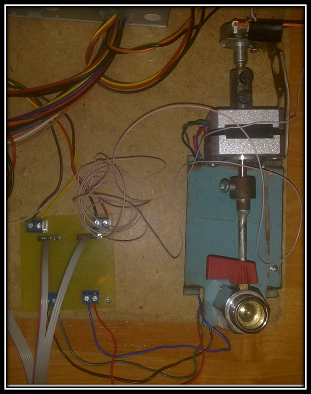
In this article, I lowered many of the points for pinouting and connecting devices to each other, circuit boards, and some other details (working with the ADC) and tried to focus on working with the periphery. Unfortunately, the assembled working model was handed over to the university (hopefully, future generations will be interested in this work and continue it), with the result that I cannot demonstrate its work, but I still have several photos. Here, for example, a photo when we conducted an experiment to determine the amplitude of the acceleration when moving the physical model of the vehicle along a sinusoidal surface with different stiffness of the air suspension.

I will also attach a project for IAR under STM32F3. There is a lot of "bad" code there, as it was written mostly on the principle "just to make it work, and as soon as possible." For any comments on the code, and not only, I will be grateful.
dl.dropboxusercontent.com/u/61862295/VirtualComport_Loopback.rar
I would like to express my gratitude to the university, which taught me a lot during these long 6 years, and to my diploma supervisor, who was moderately responsive and always helped me with “scientific” activities.

1. STM32F3 Discovery kit firmware package, including 28 examples and preconfigured projects for 4 different IDEs www.st.com/web/en/catalog/tools/PF258154
2. Datasheets for all listed devices.
The aim of the work was to develop a system for sensing and controlling a mobile robot. Behind these loud words is not very big, but for me an interesting task.
Closer to the point. We have a microprocessor, a pack of sensors, a stepping engine and it is necessary that the microprocessor reads data from the sensors (accelerometers and gyroscopes), sends this information to a PC, receives the engine control command from a computer, rotated the engine.
Purchase:
He stopped his choice on the following components:
')
• STM32F3DISCOVERY, since it has an accelerometer and gyroscope already installed on board. Yes, and under the STM32, there are already many ready-made examples, which should have facilitated the task (partly facilitated).
• Digital accelerometers LIS331DH, 3-axis, high-precision (from 2g to 8g). In general, almost the entire LIS * series is very good and fits the requirements.
• The step engine FL42STH25-0404A, well, here that the favorite department was lying around, it went into business.
An interesting point is that in the course of the work I searched for articles and information specifically on STM32F3, and I was surprised that there are not as many of them as expected (for example, on STM32F4 many times more examples and information). Yes, you say that there is almost no difference, and you will be partly right, but working with the periphery they have in some places different. That's why I decided to deposit my 5 kopecks to work with this microprocessor.
Quietly understand:
We take out the STM32F3DISCOVERY from the box, connect it to the PC and launch it. The demoprogram shows that when the deviations of the light bulb blink, that is, the sensors are working. We shout “Hurray!” And crawl into the code to understand and actually implement the necessary.
A lot of necessary, but first decided to stay on how to reach external sensors (not airborne). Accelerated axel, connect. Axels have 2 interfaces for connection: SPI and I2C. I decided to stop at SPI, because I had to deal with it on ATTINY2313 (implemented it programmatically) and thought that there shouldn't be any problems with hardware SPI at all.
Wanted as easier, it turned out as always
Connection: MISO - MISO, MOSI - MOSI, SCK - SCK, CS can be hung on any leg, as we will pull it programmatically.
First we need to initialize SPI. In this example, the work goes with SPI2, since the built-in gyroscope (or Axel, I do not remember exactly) works through the first SPI:
void SPI2_Configuration(void) { RCC_AHBPeriphClockCmd(RCC_AHBPeriph_GPIOB, ENABLE); RCC_APB1PeriphClockCmd(RCC_APB1Periph_SPI2, ENABLE); GPIO_InitTypeDef GPIO_InitStructure; NVIC_InitTypeDef NVIC_InitStructure; GPIO_InitStructure.GPIO_Pin = GPIO_Pin_13 | GPIO_Pin_14 | GPIO_Pin_15; GPIO_InitStructure.GPIO_Speed = GPIO_Speed_50MHz; GPIO_InitStructure.GPIO_Mode = GPIO_Mode_AF; GPIO_InitStructure.GPIO_OType = GPIO_OType_PP; GPIO_InitStructure.GPIO_PuPd = GPIO_PuPd_NOPULL; GPIO_Init(GPIOB, &GPIO_InitStructure); GPIO_PinAFConfig(GPIOB, GPIO_PinSource13, GPIO_AF_5); // SCK GPIO_PinAFConfig(GPIOB, GPIO_PinSource14, GPIO_AF_5); // MISO GPIO_PinAFConfig(GPIOB, GPIO_PinSource15, GPIO_AF_5); // MOSI SPI_InitTypeDef SPI_InitStructure; SPI_StructInit(&SPI_InitStructure); SPI_I2S_DeInit(SPI2); SPI_InitStructure.SPI_BaudRatePrescaler = SPI_BaudRatePrescaler_256; SPI_InitStructure.SPI_CPHA = SPI_CPHA_1Edge; SPI_InitStructure.SPI_CPOL = SPI_CPOL_Low; SPI_InitStructure.SPI_DataSize = SPI_DataSize_16b; SPI_InitStructure.SPI_Direction = SPI_Direction_2Lines_FullDuplex; SPI_InitStructure.SPI_FirstBit = SPI_FirstBit_MSB; SPI_InitStructure.SPI_Mode = SPI_Mode_Master; SPI_InitStructure.SPI_NSS = SPI_NSS_Soft; SPI_InitStructure.SPI_CRCPolynomial = 7; SPI_Init(SPI2, &SPI_InitStructure); /* Configure the Priority Group to 1 bit */ NVIC_PriorityGroupConfig(NVIC_PriorityGroup_2); /* Configure the SPI interrupt priority */ NVIC_InitStructure.NVIC_IRQChannel = SPI2_IRQn; NVIC_InitStructure.NVIC_IRQChannelPreemptionPriority = 1; NVIC_InitStructure.NVIC_IRQChannelSubPriority = 0; NVIC_InitStructure.NVIC_IRQChannelCmd = ENABLE; NVIC_Init(&NVIC_InitStructure); /* Initialize the FIFO threshold */ SPI_RxFIFOThresholdConfig(SPI2, SPI_RxFIFOThreshold_QF); SPI_Cmd(SPI2, ENABLE); } We are trying to read data from the WHO_AM_I register:
getValue = getRegisterValue(&AXELx, 0x0F);Where
char getRegisterValue(AXEL_TypeDef* AXELx, char address) { AXELx->CS_Port->BRR = AXELx->CS_Pin; SPI_I2S_SendData16(SPI2, 0x8000|(address<<8)); while(!SPI_I2S_GetFlagStatus(SPI2,SPI_I2S_FLAG_RXNE)); AXELx->CS_Port->BSRR = AXELx->CS_Pin; return SPI_I2S_ReceiveData16(SPI2); } Here it is necessary to note an important nuance that we need to pull the CS of the accelerometer, which we are addressing, in time, as pressing CS to the ground initiates the start of data transfer (because of this moment I had severe plugs and problems, plus not all axels successfully soldered and some It turned out to be non-working, which stopped my work for about two weeks. O_o). Then we send the address of the register with which we will work (read / write), read or write with the second byte.
Well, we will write like this:
void setRegisterValue(AXEL_TypeDef* AXELx, char address, char data) { AXELx->CS_Port->BRR = AXELx->CS_Pin; SPI_I2S_SendData16(SPI2,((short)address<<8)|(short)data); while(!SPI_I2S_GetFlagStatus(SPI2,SPI_I2S_FLAG_RXNE)); AXELx->CS_Port->BSRR = AXELx->CS_Pin; SPI_I2S_ReceiveData16(SPI2); } For correct operation, the sensors also need to be initialized, namely, indicate that we will read on all three axes and indicate the operating frequency (the value of the control word and its formation are viewed in the datasheet on the axel).
void Axel_Init(AXEL_TypeDef* AXELx) { GPIO_InitTypeDef GPIO_InitStructure; /* Enable Axel CS Pin */ GPIO_InitStructure.GPIO_Mode = GPIO_Mode_OUT; GPIO_InitStructure.GPIO_Speed = GPIO_Speed_50MHz; GPIO_InitStructure.GPIO_OType = GPIO_OType_PP; GPIO_InitStructure.GPIO_Pin = AXELx->CS_Pin; GPIO_Init(AXELx->CS_Port, &GPIO_InitStructure); setRegisterValue(AXELx, 0x20, 0x27); } With the sensors finished, hooray! Now let's move on to the management of stepper motors.
The quieter you go, the further you'll get
The driver VNH3SP30 was used to control the stepper motor. True, it allows you to control only one of the two windings of a stepper motor, so we need 2 such scarves.
Thus, to control one winding, we need 3 outputs from the microcontroller (one carrier frequency and 2 directions), for the entire engine - 6.
Define ports for convenience:
#define A_PULSE_PORT GPIOB #define A_PULSE_PIN GPIO_Pin_2 #define A_DIR1_PORT GPIOB #define A_DIR1_PIN GPIO_Pin_0 #define A_DIR2_PORT GPIOE #define A_DIR2_PIN GPIO_Pin_8 #define B_PULSE_PORT GPIOE #define B_PULSE_PIN GPIO_Pin_12 #define B_DIR1_PORT GPIOE #define B_DIR1_PIN GPIO_Pin_10 #define B_DIR2_PORT GPIOE #define B_DIR2_PIN GPIO_Pin_14 And we initialize them:
void StepMotorSetup() { RCC_AHBPeriphClockCmd(RCC_AHBPeriph_GPIOB | RCC_AHBPeriph_GPIOE, ENABLE); /* */ GPIO_InitTypeDef GPIO_InitStructure; GPIO_InitStructure.GPIO_OType = GPIO_OType_PP; GPIO_InitStructure.GPIO_PuPd = GPIO_PuPd_NOPULL; GPIO_InitStructure.GPIO_Speed = GPIO_Speed_50MHz; GPIO_InitStructure.GPIO_Mode = GPIO_Mode_OUT; GPIO_InitStructure.GPIO_Pin = A_PULSE_PIN; GPIO_Init(A_PULSE_PORT, &GPIO_InitStructure); GPIO_InitStructure.GPIO_Pin = B_PULSE_PIN; GPIO_Init(B_PULSE_PORT, &GPIO_InitStructure); GPIO_InitStructure.GPIO_Pin = A_DIR1_PIN; GPIO_Init(A_DIR1_PORT, &GPIO_InitStructure); GPIO_InitStructure.GPIO_Pin = B_DIR1_PIN; GPIO_Init(B_DIR1_PORT, &GPIO_InitStructure); GPIO_InitStructure.GPIO_Pin = A_DIR2_PIN; GPIO_Init(A_DIR2_PORT, &GPIO_InitStructure); GPIO_InitStructure.GPIO_Pin = B_DIR2_PIN; GPIO_Init(B_DIR2_PORT, &GPIO_InitStructure); } In order to make 1 step the engine needs to turn on the motor windings in the necessary order, that is, to send control signals to the driver
The mask of control signals is as follows:
u8 WireConFullStep[4][4] = {{1, 0, 0, 0}, {0, 0, 1, 0}, {0, 1, 0, 0}, {0, 0, 0, 1}}; And now we take a step in the right direction. The direction in this case is determined by the direction of detour by the mask of control signals:
void DoStep(int index) { GPIO_ResetBits(A_DIR1_PORT, A_DIR1_PIN); GPIO_ResetBits(A_DIR2_PORT, A_DIR2_PIN); GPIO_ResetBits(B_DIR1_PORT, B_DIR1_PIN); GPIO_ResetBits(B_DIR2_PORT, B_DIR2_PIN); GPIO_ResetBits(A_PULSE_PORT, A_PULSE_PIN); GPIO_ResetBits(B_PULSE_PORT, B_PULSE_PIN); if(WireConFullStep[index][0] == 1) { GPIO_SetBits(A_DIR1_PORT, A_DIR1_PIN); GPIO_SetBits(A_PULSE_PORT, A_PULSE_PIN); } if(WireConFullStep[index][1] == 1) { GPIO_SetBits(A_DIR2_PORT, A_DIR2_PIN); GPIO_SetBits(A_PULSE_PORT, A_PULSE_PIN); } if(WireConFullStep[index][2] == 1) { GPIO_SetBits(B_DIR1_PORT, B_DIR1_PIN); GPIO_SetBits(B_PULSE_PORT, B_PULSE_PIN); } if(WireConFullStep[index][3] == 1) { GPIO_SetBits(B_DIR2_PORT, B_DIR2_PIN); GPIO_SetBits(B_PULSE_PORT, B_PULSE_PIN); } } For convenience, we define a step counterclockwise and a step clockwise:
void CWStep() { DoStep(CurIndex); CurIndex+=1; if(CurIndex > 3) CurIndex = 0; } void CCWStep() { DoStep(CurIndex); CurIndex-=1; if(CurIndex < 0) CurIndex = 3; } And now we will write a function, with the help of which we will rotate the engine for the required number of steps in the right direction:
void Steps(u8 dir, s16 n) { s16 i = 0; for(i = 0; i < n; i++) { if(dir) { CWStep(); udelay(15000); } else { CCWStep(); udelay(15000); } } } In this function, time delays are inserted so that the stepper motor has time to take a step before we send the command of the next step.
The power in our hands is becoming more and more and we move on to the next stage - sending data to the PC and controlling the SD from the PC.
USB communication
To work with USB, I used one of the examples of working with USB, namely the VirtualComport_Loopback (look for the Internet in the STM32 USB-FS-Device development kit). In this demo, the connected stm32 to the PC was defined as a virtual com-port, and sent back all received data. Well, this is great for us! We take this example, break the loop of exchange and voila - use it.
The only problem that arose was that the application on .Net did not want to connect to the virtual com-port if the microprocessor constantly interrogated the sensor and sent the data to the PC (interestingly, the third-party Hercules program, which I used for debugging, perfectly opened the port). Therefore, I decided to add the wait for pressing the User Button, after which the constant interrogation of sensors and the exchange of information with the PC had already begun.
Actually, the following code came out:
USB initialization:
Set_System(); Set_USBClock(); USB_Interrupts_Config(); USB_Init(); We wait until we click the User Button:
while (1) { /* Data exhange via USB */ if (bDeviceState == CONFIGURED && UserButtonPressed != 0) { … } } Handler on pressing UserButton:
__IO uint32_t i =0; extern __IO uint32_t UserButtonPressed; void EXTI0_IRQHandler(void) { if ((EXTI_GetITStatus(USER_BUTTON_EXTI_LINE) == SET)&&(STM_EVAL_PBGetState(BUTTON_USER) != RESET)) { /* Delay */ for(i=0; i<0x7FFFF; i++); /* Wait for SEL button to be pressed */ while(STM_EVAL_PBGetState(BUTTON_USER) != RESET); /* Delay */ for(i=0; i<0x7FFFF; i++); UserButtonPressed++; if (UserButtonPressed > 0x2) { UserButtonPressed = 0x0; } /* Clear the EXTI line pending bit */ EXTI_ClearITPendingBit(USER_BUTTON_EXTI_LINE); } } Conclusion
In this article, I lowered many of the points for pinouting and connecting devices to each other, circuit boards, and some other details (working with the ADC) and tried to focus on working with the periphery. Unfortunately, the assembled working model was handed over to the university (hopefully, future generations will be interested in this work and continue it), with the result that I cannot demonstrate its work, but I still have several photos. Here, for example, a photo when we conducted an experiment to determine the amplitude of the acceleration when moving the physical model of the vehicle along a sinusoidal surface with different stiffness of the air suspension.
I will also attach a project for IAR under STM32F3. There is a lot of "bad" code there, as it was written mostly on the principle "just to make it work, and as soon as possible." For any comments on the code, and not only, I will be grateful.
dl.dropboxusercontent.com/u/61862295/VirtualComport_Loopback.rar
I would like to express my gratitude to the university, which taught me a lot during these long 6 years, and to my diploma supervisor, who was moderately responsive and always helped me with “scientific” activities.
Sources used:
1. STM32F3 Discovery kit firmware package, including 28 examples and preconfigured projects for 4 different IDEs www.st.com/web/en/catalog/tools/PF258154
2. Datasheets for all listed devices.
Source: https://habr.com/ru/post/183856/
All Articles